

Page 1
REPAIR MANUAL
PRODUCT: DISHWASHER
MODEL: L 63 / LL 64 / LL 65
LI 640 / LI 670 / LI 700
The information included in this Ariston Repair Manual may change without notice. Please see our web site
www.usservicenet.com for updates, corrections or additions.
Pages:
1 - 33
Page 2

REPAIR MANUAL
SAFE SERVICE PRACTICES
This Repair Manual is intended for persons having electrical and mechanical training and a level of knowledge
of these subjects generally considered acceptable in the Appliance Service Industry. Ariston cannot be
responsible, nor assumes any liability for injury or damages of any kind arising from the use or misuse of
the information contained in this Repair Manual.
If you have any questions regarding the proper diagnosis, repair or operation of any Ariston Appliance, please
contact the Ariston Customer Care Center or your Service Representative.
SERVICING SAFEGAURDS:
To avoid personal injury and/or property damage, it is important that safe servicing practices be observed at all times. Examples of
safe service practices are listed below but are not limited to the following:
1) Never attempt a product repair if you have any doubts as to your ability to complete the repair in a safe and
satisfactory manner.
2) Before servicing or removing an appliance:
- Disconnect power to the appliance.
- Turn off the gas / LP supply.
- Turn off the water supply.
3) Never interfere with the proper operation of any safety device.
4) Use only genuine factory replacement parts as substitutions may interfere with compliances to home safety codes or standards.
5) It is extremely important that all safety ground connections be reestablished prior to the completion of the service call. Failure to
do so will result in a hazardous condition being created.
6) Prior to returning the appliance back into active service, ensure the following:
- All electrical connections are correct and secure.
- Electrical leads are properly dressed and secured away from sharp edges, high temperature components and moving parts.
- All non-insulated electrical terminals, connectors, heaters, etc. are adequately spaced away from metal parts or panels.
- All safety grounds (both internal and external) are correctly and securely connected.
- All access panels are properly and securely reassembled.
Page: i
Page 3

L 63 / LL 64 / LL 65
REPAIR MANUAL
LI 640 / LI 670 / LI 700
TABLE OF CONTENTS
Page
1. Model and Serial Number Location ................................................................................................1
2. Rack Rollers - Upper & Lower........................................................................................................ 2
3. Upper Spray Arm............................................................................................................................ 2
4. Lower Spray Arm............................................................................................................................ 3
5. Outer Door Panel............................................................................................................................ 4
6. Control Panel .................................................................................................................................. 5
7. Outer Door Skin.............................................................................................................................. 6
8. Soap Dispenser and Water Temperature NTC............................................................................... 7
9. Door Spring Adjustment and Door Latch........................................................................................7
10. Kick Plate .......................................................................................................................................8
11. Door Extension............................................................................................................................... 9
12. Water Valve..................................................................................................................................10
13. Float Switch and Pressure Switch................................................................................................ 11
14. Lower Component Access - Base Pane Removal........................................................................12
15. Lower Components...................................................................................................................... 13
16. Drain Motor................................................................................................................................... 14
17. Main Motor and Pump.................................................................................................................. 15
18. Heater Assembly.......................................................................................................................... 17
19. Turbidity Sensor (LI 670 / LI 700 Models Only)............................................................................................ 18
20. Water Softener............................................................................................................................. 19
Page: ii
Page 4

L 63 / LL 64 / LL 65
REPAIR MANUAL
LI 640 / LI 670 / LI 700
TABLE OF CONTENTS Cont.
Page
21. High Pressure Switch................................................................................................................... 20
22. Fan Motor (LL 65 / LI 700 Models Only)......................................................................................................20
23. Water Inlet and Turbine................................................................................................................21
24. Fault Codes..................................................................................................................................22
25. Schematics................................................................................................................................... 23
Page: iii
Page 5
REPAIR MANUAL
L 63 / LL 64 / LL 65
LI 640 / LI 670 / LI 700
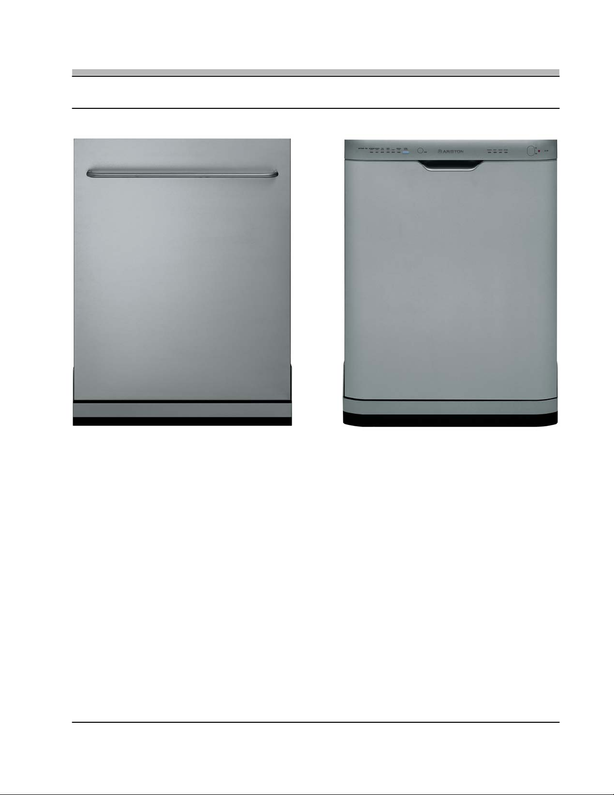
LI 700 S LL 64 S
This Dishwasher Repair Manual uses the LI 700 S model for all repair instructions and demonstrations. The
technical similarities between the LI 700 S and the other LI , L and LL models will allow the repair techniques
described and demonstrated to be applied without difficulty to the other models not shown.
Page: iv
Page 6
REPAIR MANUAL
1. MODEL and SERIAL NUMBER LOCATION
L 63 / LL 64 / LL 65
LI 640 / LI 670 / LI 700
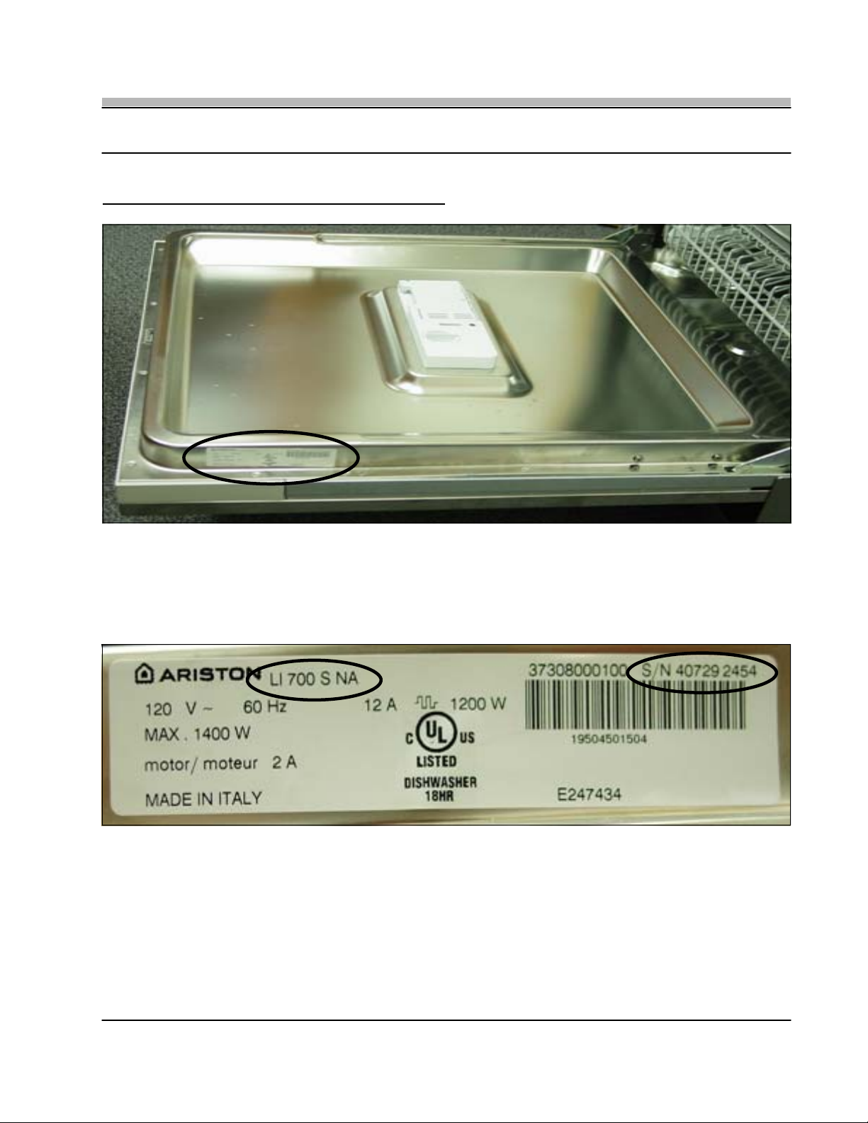
Fig. 1-1
• The Model and Serial Number Tag is located on the right side of the Inner Door Panel (Fig. 1-1). The Model shown is a LI 700 S
with a Serial Number of 407292454 (Fig. 1-2).
Note: Numbers located to the left of the nine (9) digit Serial Number are not required on the Warranty Claim Form.
Fig. 1-2
Page: 1
Page 7
REPAIR MANUAL
2. RACK ROLLERS - Upper & Lower
L 63 / LL 64 / LL 65
LI 640 / LI 670 / LI 700
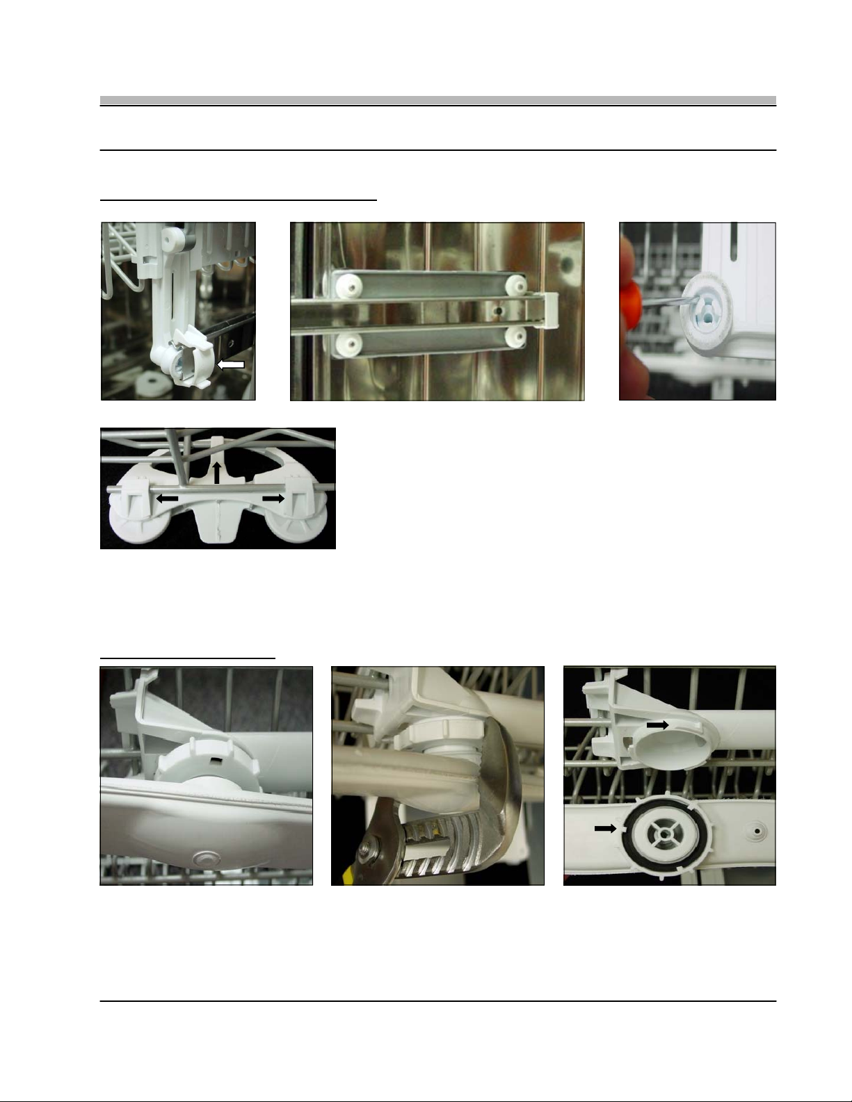
Fig. 2-1
Fig. 2-2
Fig. 2-3
• The Upper Rack can be removed by releasing the Rail Clip and slidin g the
Rack out from the Rail (Fig. 2-1). If the Upper Rack Roller Assembly must be
replaced (Fig 4-2) first remove the Side Panel (see Section 22) and then
remove the four (4) 8mm bolts that mount the Roller Assembly to the Tank.
• Once the Upper Rack has been removed, the Rack Roller Wheels can be
replaced by gently prying the Hub Clips inward with a small screwdriver and
Fig. 4-4
then moving the Roller Wheel out and off the Hub (Fig. 2-3).
• The Lower Rack Roller Assemblies are held in place using three (3) tension clips (Fig 2-4). Grasping the Roller Assembly and
applying downward force will disengage the Roller Assembly from the Rack.
3. UPPER SPRAY ARM
Fig. 3-1 Fig. 3-2 Fig. 3-3
• To remove the Upper Spray Arm (Fig. 3-1) gently grasp the Locki ng Ring with a Channel Locks and turn Counter-Clockwise
(Fig. 3-2); note the Tab and Slot locking configuration (Fig. 3-3).
TECH NOTE: When Replacing the Spray Arm make sure that it is tightened completely onto the Locking Ring.
Page: 2
Page 8
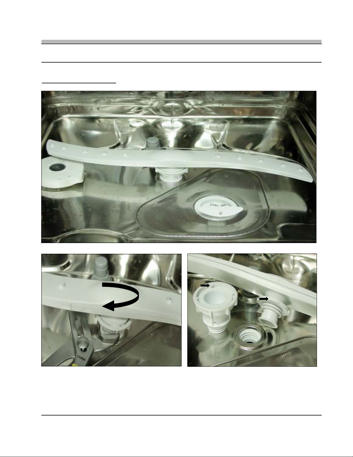
4. LOWER SPRAY ARM
REPAIR MANUAL
L 63 / LL 64 / LL 65
LI 640 / LI 670 / LI 700
Fig. 4-1
Fig. 4-2
Fig. 4-3
• To remove the Lower Spray Arm (Fig. 4-1) hold the Spray Arm Locking Ring with a Channel Locks and then turn the Spray Arm
Clockwise (Fig. 4-2). The Locking Ring Assembly can also be removed by rotating it Counter-Clockwise; note the Tab and Slot
locking configuration (Fig. 4-3).
TECH NOTE: When Replacing the Spray Arm make sure that it is tightened completely onto the Locking Ring.
Page: 3
Page 9
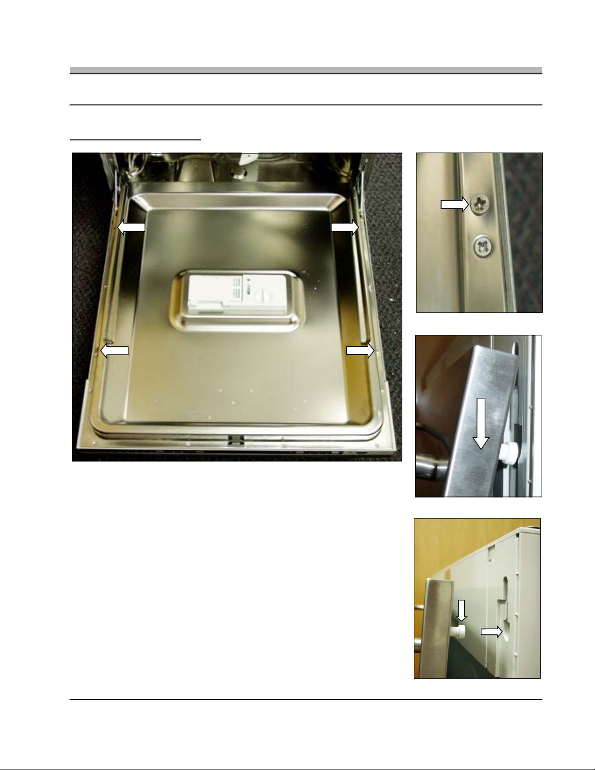
5. OUTER DOOR PANEL
REPAIR MANUAL
L 63 / LL 64 / LL 65
LI 640 / LI 670 / LI 700
A
B
• The Outer Door is held in place using four (4) Phillips screws (Fig. 5-1). Screw “A” is a
single screw located on the bottom left and right corners of the Inner Door Panel. Screw
“B” is just below the Phillips screw that holds the Outer Door Skin (Fig. 5-2).
• With the four (4) screws removed raise the Door to an upright position and t hen slide
the Outer Door Panel down and out from the Alignment Channel (Fig. 5-3).
• When replacing the Outer Door insert the Alignment Pin into the Channel and then raise
the Door Panel up until it is even with the top of the Control Panel (Fig. 5-4).
TECH NOTE: To prevent damage to the Outer Door, Alignment Pins, or Channel, make
sure to support the weight of the Door as you remove or replace it.
A
B
Fig. 5-1
B
Fig. 5-2
Fig. 5-3
Fig. 5-4
Page: 4
Page 10
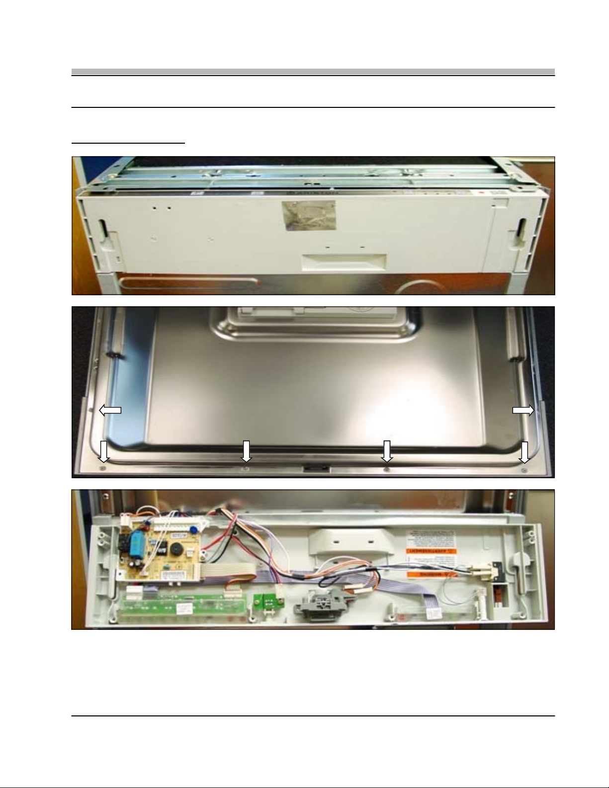
6. CONTROL PANEL
REPAIR MANUAL
L 63 / LL 64 / LL 65
LI 640 / LI 670 / LI 700
Fig. 6-1
Fig. 6-2
Fig. 6-3
• To remove the Control Panel (Fig. 6-1), remove the six (6) Phillips Control Panel screws from the Inner Door Panel (Fig 6-2). With
the screws removed the Control Panel will lay forward and is now accessible for repair (Fig. 6-3).
TECH NOTE: The Outer Door must be removed first (see Section 5) before removing the Control Panel Screws.
Page: 5
Page 11

7. OUTER DOOR SKIN
REPAIR MANUAL
L 63 / LL 64 / LL 65
LI 640 / LI 670 / LI 700
A
B
A
B
B
Fig. 7-1
• To remove the Outer Door Skin, first remove the Outer Door Panel ( see Section 5). Now remove the four (4) remaining Phillips
screws. Two (2) screws “A” are located half way up the Inner Door Panel and screws “B” are located above the Outer Door Panel
screws (Fig. 7-1 & 7-2). With the Outer Door Skin removed you have access to the Soap Dispenser (Fig. 7-3) and Door Hinges.
TECH NOTE: The Control Panel does not have to be
removed to remove the Outer Door Skin.
Fig. 7-2
Fig. 7-3
Page: 6
Page 12

REPAIR MANUAL
8. SOAP DISPENSER and WATER TEMPERATURE NTC
L 63 / LL 64 / LL 65
LI 640 / LI 670 / LI 700
Fig. 8-1
• To remove the Soap Dispenser (Fig. 8-1), first remove the Actuator Solenoid wiring and then the six (6) Phillips screws that mount
the Dispenser to the Inner Door. The Dispenser can then be removed and replaced as a complete assembly.
OPERATION: The Actuator Solenoid is energized twice during a complete cycle. The first actuation releases the Detergent and
also aligns the Dispenser Linkage for the second actuation which releases the Rinse Agent.
TECH NOTE: Located on the upper right corner of the Dispenser is the Water Temperature NTC. The NTC is hard wired to the
Main Control Board. If the NTC proves faulty the Main Control Board must be replaced. Also, Dishwasher Models
L63 / LL64 / LI 640 / LI 670 incorporate a Magnetic Reed Switch to activate the Rinse Aid LED. Models LL 65 &
LI 700 use a Turbidity Sensor, see Section 19 for details.
9. DOOR SPRING ADJUSTMENT and DOOR LATCH
Fig. 9-1
• To adjust the tension on the Outer Door turn the two (2) 5mm Allen Screws Clockwise for
more spring tension and Counter Clockwise for less spring tension (Fig. 9-1).
• The Door Latch can be adjusted using a 7mm Nut Driver (Fig. 9-2)
Fig. 9-2
Page: 7
Page 13

10. TOE KICK
REPAIR MANUAL
L 63 / LL 64 / LL 65
LI 640 / LI 670 / LI 700
A
Fig. 10-1 Fig. 10-2
• The Toe Kick is a tension fit and mounts into the Side Support Plates “A” located on the left and right lower corners of the
Dishwasher. The Toe Kick is held in place and adjusted using a dimple stamped into the Toe Kick (Fig. 10-1). Once the Toe Kick is
inserted into the Support Plate you can adjust the Toe Kick to the required height by simply sliding it up or down (Fig. 10-2).
To remove the Toe Kick firmly pull it toward you.
TECH NOTE: When installing the Toe Kick remember that it fits inside the left and right Side Support Plates (Fig. 10-2).
A
Page: 8
Page 14

11. DOOR EXTENSION
REPAIR MANUAL
L 63 / LL 64 / LL 65
LI 640 / LI 670 / LI 700
Fig. 11-1
Fig. 11-3
Fig. 11-4
• The Door Extension (Fig. 11-1 & 11-2) is secured to the Dishwasher using two
(2) tension clips (Fig. 11-3 & 11-4) on both the left and right sides. The tension
clips insert into cut-outs on the left and right Side Support Plates (Fig. 11-5).
• To remove the Door Extension, first release the center clip (Fig. 11-2). Then
push out on the right side, this will disengage the locking clips.
TECH NOTE: Access to the Door Extension can be made easier if the
Dishwasher Door is opened slightly. Do not attempt to pull the
Door Extension forward to remove, this may damage the
locking clips.
• When re-installing the Door Extension make sure to align the lower corners
onto the small rail that is located on the bottom of the Side Support Plate
(Fig.11-6). Once in position on the rail, the Door Extension can be pivoted into
place and the tension clips locked it into position.
Fig. 11-2
Fig. 11-5
INSIDE LEFT CORNER
Fig. 11-6
Page: 9
Page 15

12. WATER VALVE
REPAIR MANUAL
L 63 / LL 64 / LL 65
LI 640 / LI 670 / LI 700
Fig. 12-1
Fig. 12-2
Fig. 12-3
• To access the Water Valve, first remove the Toe Kick (see Section 10) and the Door Extension (see Section 11) (Fig. 12-1). The
Water Valve is held in place with two (2) Phillips screws (Fig. 12-2), remove the two screws and the Valve can be easily accessed.
TECH NOTE: A new Valve Hose Clamp (Fig. 12-3) is included with the replacement Water Valve, but the old Clamp can be
reused if carefully removed.
Page: 10
Page 16

REPAIR MANUAL
13. FLOAT SWITCH and PRESSURE SWITCH
L 63 / LL 64 / LL 65
LI 640 / LI 670 / LI 700
Fig. 13-1
Fig. 13-2
Fig. 13-3
Fig. 13-4
• To access the Float Switch or Pressure Switch, first remove the Toe Kick (see Section 10) and the Door Extension (see Section
11) then remove the four (4) Phillips screws that hold the Lower Access Panel to the Dishwasher (Fig. 13-1). With the screws
removed the Lower Access Panel can be moved down and out allowing access to the two components (Fig. 13-2).
Float Switch: (Fig. 13-3) Can be checked for continuity or for water in the Base Pan.
Pressure Switch: (Fig.13-4) Can be checked for continuity.
Page: 11
Page 17

REPAIR MANUAL
14. LOWER COMPONENT ACCESS - BASE PAN REMOVAL
Front Adjustable Rear Legs (7mm)
L 63 / LL 64 / LL 65
LI 640 / LI 670 / LI 700
Fig. 14-1
Rear View
Fig. 14-3
Fig. 14-2
• TO ACCESS THE LOWER
C O M P O N E N T S T H E
DISHWASHER MUST BE
REMOVED FROM THE
CABINET.
• With the Dishwasher removed
from the cabinet, remove the
Base Pan Screws, there are
three (3) Phillips screws on the
lower front of the unit (Fig. 14-1)
and three (3) Phillips screws on
the rear (Fig. 14-2).
• Carefully place the Dishwasher
on its back and remove the
Base Pan (Fig. 14-3). The
Lower Components are now
accessible.
Page: 12
Page 18

15. LOWER COMPONENTS
A
REPAIR MANUAL
L 63 / LL 64 / LL 65
LI 640 / LI 670 / LI 700
B
• With the Bottom Pan removed you have access to the following components:
A: Water Softener.
B: Main Motor and Pump.
C: Heater.
D: Drain Motor.
E: Turbo Dry Fan Motor (only on the LL 65 / LI 700 Models).
C
D
E
Fig. 15-1
Page: 13
Page 19

16. DRAIN MOTOR
REPAIR MANUAL
L 63 / LL 64 / LL 65
LI 640 / LI 670 / LI 700
Fig. 16-1
Fig. 16-2
Fig. 16-3
• To remove the Drain Motor (Fig. 16-1), first loosen the Drain Hose Clamp and Drain Hose, then remove the single Phillips
mounting screw. (Fig. 16-2). The Drain Motor is secured to the Sump using a tab and slot twist lock mount. With the Drain Hose
and mounting screw removed twist the Drain Motor Clockwise to remove (Fig.16-3).
TECH NOTE: For a better seal lubricate the new Drain Motor Gasket before installing, and make sure all three (3) Tabs are
secured into the corresponding slots, then twist the motor into position.
Page: 14
Page 20

17. MAIN MOTOR and PUMP
REPAIR MANUAL
L 63 / LL 64 / LL 65
LI 640 / LI 670 / LI 700
Fig. 17-1
Fig. 17-2
Fig. 17-3
• To remove the Main Motor and Pump Assembly (Fig. 17-1), first remove the Vibration Damper from the rear of the Motor by prying
it away from the Motor with a screwdriver (Fig. 17-2). Next remove the Motor and Pump Assembly from the three (3) hose
connections (Fig. 17-3) See TECH NOTE below.
TECH NOTE: The Motor Assembly can be removed from the three (3) hoses without undoing the Hose Clamps. Easily work the
Pump out and off the Hoses, the Clamps can now be reused if necessary.
Page: 15
Page 21

REPAIR MANUAL
17. MAIN MOTOR and PUMP Cont.
L 63 / LL 64 / LL 65
LI 640 / LI 670 / LI 700
Fig. 17-4
Fig. 17-6
Fig. 17-5
Fig. 17-7
• Once the Main Motor and Pump has been removed from the Dishwasher (Fig. 17-4) it can be separated and the Motor or Pump
replaced. To separate the Motor from the Pump, first remove the two (2) Phillips screws located on the left and right sides of the
pump (Fig. 17-5). Next, using a 13mm socket and regular screwdriver loosen the Pump Impeller from the Motor Shaft By turning it
clockwise (Fig. 17-5). The Motor or Pump can now be replaced (Fig. 17-6)
• The LL 65 and the LI 700 Models have a Top Rack Wash feature. The Top Rack Wash is controlled by a Solenoid Valve on the
pump that when energized blocks the flow of water to the Lower Wash Arm. If required the Solenoid can be replaced by removing
the four (4) Phillips screws that mount it to the Pump (Fig. 17-7). The complete Pump Assembly does not have to be replaced.
Page: 16
Page 22

18. HEATER ASSEMBLY
REPAIR MANUAL
L 63 / LL 64 / LL 65
LI 640 / LI 670 / LI 700
Fig. 18-1
Fig. 18-2
• To remove the Heater Assembly, first remove the Drain Motor as described in Section 16 (Fig. 18-1). With the Drain Motor
removed you have full access to the Heater Assembly (Fig. 18-2).
Page: 17
Page 23

18. HEATER ASSEMBLY Cont.
REPAIR MANUAL
L 63 / LL 64 / LL 65
LI 640 / LI 670 / LI 700
Fig. 18-3
Fig. 18-4
• With the Drain Motor removed, remove the two Heater Assembly Clamps (Fig. 18-3) and then gently separate the Heater
Assembly from the two (2) Hoses.
OPERATION: The Heater is a Flow-Through design that also incorporates an internal High Limit (Fig. 18-4). Both the Heating
Element and the High Limit can be checked for continuity, but the Heater is replaced as a complete assembly.
19. TURBIDITY SENSOR (LI 670 / LI 700 Models Only)
Fig. 19-1
Fig. 19-2
• The LI 670 and LI 700 Dishwasher models incorporate a Turbidity Sensor that measures water clarity and may adjusts cycle times
if required. The Turbidity Sensor is a small PC Board mounted inside a black housing attached to the input of the Heater Assembly
Hose. To replace, simply open the housing and remove the PC Board.
Page: 18
Page 24

20. WATER SOFTENER
REPAIR MANUAL
L 63 / LL 64 / LL 65
LI 640 / LI 670 / LI 700
Fig. 21-2
Fig. 20-1
Fig. 20-3
• All Dishwasher models are equipped with a built in Water Softener. The Water Softener Assembly is a self contained unit and
should rarely require servicing (Fig. 20-4). However, a Solenoid Valve located on the Water Softener Assembly (Fig. 20-1) may
require replacing. The Water Softener and Solenoid Valve is replaced as a complete assembly.
• To replace the Assembly, remove the Water Softener Cap from inside the Dishwasher (Fig. 20-2), then remove the retaining nut
(Fig. 20-3). Next, uninstall the Dishwasher and remove the Base Pan as explained in Section 12. Remove the Softener Hoses and
replace the Water Softener as a complete assembly (Fig. 20-4).
OPERATION: The Softener Indicator LED will light
every thirty (30) wash cycles
indicating that the salt in the Softener
needs to be refilled.
TECH NOTE: After the Softener has been filled with
salt. the LED will remain on for five (5)
cycles even if the Softener is full.
It is possible to reset the LED by
pouring a cup of water into the sump
before the beginning of a new cycle.
Fig. 20-4
Page: 19
Page 25

21. HIGH PRESSURE SWITCH
Fig. 21-1
L 63 / LL 64 / LL 65
REPAIR MANUAL
LI 640 / LI 670 / LI 700
• The High Pressure Switch (Fig. 21-1) is located on the output hose of the
Pump that supplies the Lower Wash Arm. The High Pressure Switch is
Normally Closed (NC) during Dishwasher operation.
OPERATION: When the Dishwasher Filters become completely clogged
water flow through the Pump is reduced and the High
Pressure Switch contacts open. The open contacts
indicate to the Control Board that a Filter Fault exists and
the Control Board will alternately drain and fill the
Dishwasher until the Filters are clear (Filter Cleaning Cycle).
TECH NOTE: In Fig. 21-1 The Main Motor and Pump have been removed
to allow a better view of the Switch. The High Pressure
Switch can be removed and replaced without
removing the
Main Motor or Pump Assembly.
22. FAN MOTOR (LI 670 / LI 700 Models Only)
Fig. 22-1
Fig. 22-2
• The Fan Motor Assembly can be accessed by removing the eight (8) Phillips screws that attach the Right Side Panel to the
Dishwasher (Fig. 22-1). The Fan Motor Assembly consists of a large plastic Condensation Chamber and Motor (Fig. 22-2).
• To replace the Fan Motor, unscrew the Upper Vent Cover from inside the Dishwasher (arrow on Fig. 22-3) and slide the
Condensation Chamber out from the side of the Dishwasher. The Fan Motor Assembly and Condensation Chamber is replaced as
a complete assembly.
Fig. 22-3
Page: 20
Page 26

23. WATER INLET and TURBINE
Fig. 23-1 Fig. 23-2 Fig. 23-3
REPAIR MANUAL
L 63 / LL 64 / LL 65
LI 640 / LI 670 / LI 700
• Located on the Left Side of the Dishwasher is the Water Inlet and Turbine. The Water Inlet allows incoming water from the Water
Solenoid to flow into the Dishwasher as well as provide water to regenerate the Resins in the Water Softener Tank. To access the
Water Inlet remove the eight (8) Phillips screws that attach the Left Side Panel (Fig. 23-1). With the Panel removed you have
access to the Water Inlet (Fig. 23-2).
• The Turbine (Fig. 23-3 & 23-4) measures the incoming water flow via
a Magnetic Reed Switch.
OPERATION: The Main Control Board monitors the pulses coming
from the Reed Switch and calculates if too little or
too much water is entering the Dishwasher. The
Turbine works in conjunction with the Pressure
Switch to ensure the correct amount of water enters
the Dishwasher. The Turbine is also a safety over
flow device to protect against overfilling.
Fig. 23-4
Page: 21
Page 27

24. FAULT CODES
REPAIR MANUAL
L 63 / LL 64 / LL 65
LI 640 / LI 670 / LI 700
Page: 22
Page 28

25. SCHEMATIC L63
REPAIR MANUAL
L 63 / LL 64 / LL 65
LI 640 / LI 670 / LI 700
Page: 23
Page 29

25. SCHEMATIC L64
REPAIR MANUAL
L 63 / LL 64 / LL 65
LI 640 / LI 670 / LI 700
Page: 24
Page 30

25. SCHEMATIC L65
REPAIR MANUAL
L 63 / LL 64 / LL 65
LI 640 / LI 670 / LI 700
Page: 25
Page 31

25. SCHEMATIC LI640
REPAIR MANUAL
L 63 / LL 64 / LL 65
LI 640 / LI 670 / LI 700
Page: 26
Page 32

25. SCHEMATIC LI670
REPAIR MANUAL
L 63 / LL 64 / LL 65
LI 640 / LI 670 / LI 700
Page: 27
Page 33

25. SCHEMATIC LI700
REPAIR MANUAL
L 63 / LL 64 / LL 65
LI 640 / LI 670 / LI 700
Page: 28
 Loading...