

Page 1
REPAIR MANUAL
PRODUCT: CONDENSATION DRYER
MODEL: ASL75CXS NA
The information included in this Ariston Repair Manual may change without notice. Please see our web site
www.usservicenet.com for updates, corrections or additions.
Pages:
1 - 18
Page 2

REPAIR MANUAL
ASL75CXS NA
SAFE SERVICE PRACTICES
This Repair Manual is intended for persons having electrical and mechanical training and a level of knowledge
of these subjects generally considered acceptable in the Appliance Service Industry. Ariston cannot be
responsible, nor assumes any liability for injury or damages of any kind arising from the use or misuse of
the information contained in this Repair Manual.
If you have any questions regarding the proper diagnosis, repair or operation of any Ariston Appliance, please
contact the Ariston Customer Care Center or your Service Representative at 888-426-0825.
SERVICING SAFEGAURDS:
To avoid personal injury and/or property damage, it is important that safe servicing practices be observed at all times. Examples of
safe service practices are listed below but are not limited to the following:
1) Never attempt a product repair if you have any doubts as to your ability to complete the repair in a safe and
satisfactory manner.
2) Before servicing or removing an appliance:
- Disconnect power to the appliance.
- Turn off the gas / LP supply.
- Turn off the water supply.
3) Never interfere with the proper operation of any safety device.
4) Use only genuine factory replacement parts as substitutions may interfere with compliances to home safety codes or standards.
5) It is extremely important that all safety ground connections be reestablished prior to the completion of the service call. Failure to
do so will result in a hazardous condition being created.
6) Prior to returning the appliance back into active service, ensure the following:
- All electrical connections are correct and secure.
- Electrical leads are properly dressed and secured away from sharp edges, high temperature components and moving parts.
- All non-insulated electrical terminals, connectors, heaters, etc. are adequately spaced away from metal parts or panels.
- All safety grounds (both internal and external) are correctly and securely connected.
- All access panels are properly and securely reassembled.
Page: i
Page 3

REPAIR MANUAL
ASL75CXS NA
TABLE OF CONTENTS
Page
1. Control Panel ASL75CXS............................................................................................................... 1
2. Model / Serial Number Location..................................................................................................... 2
3. Top Panel....................................................................................................................................... 3
4. Control Panel .................................................................................................................................. 4
5. Control Panel Program Board......................................................................................................... 4
6. Door Switch.................................................................................................................................... 5
7. Condensation Unit..........................................................................................................................5
8. Heater Assembly............................................................................................................................ 6
9. Thermistor and High Limit Thermostat ........................................................................................... 7
10. Right Side Panel and Components................................................................................................. 8
11. Control Board and EEPROM.......................................................................................................... 9
12. Motor Replacement and Installation............................................................................................. 10
13. Drum Belt and Bearing Block........................................................................................................12
14. Drain Motor.................................................................................................................................. 13
15. Fault Codes..................................................................................................................................14
16. Schematic..................................................................................................................................... 15
Page: ii
Page 4
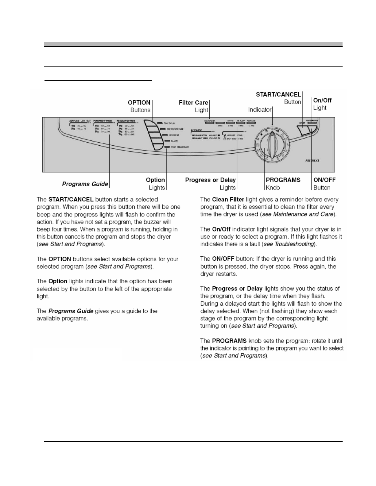
1. CONTROL PANEL ASL75CXS
REPAIR MANUAL
ASL75CXS NA
Page: 1
Page 5
REPAIR MANUAL
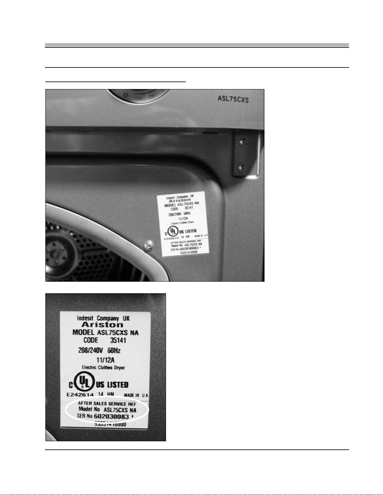
2. MODEL / SERIAL NUMBER LOCATION
ASL75CXS NA
• The Model and Serial Number
Tag is located on the front of
the Dryer behind the door
(Fig. 2-1).
Fig. 2-1
• The Model number is ASL75CXS NA with a nine (9) digit Serial
Number (Fig. 2-2).
Fig. 2-2
Page: 2
Page 6
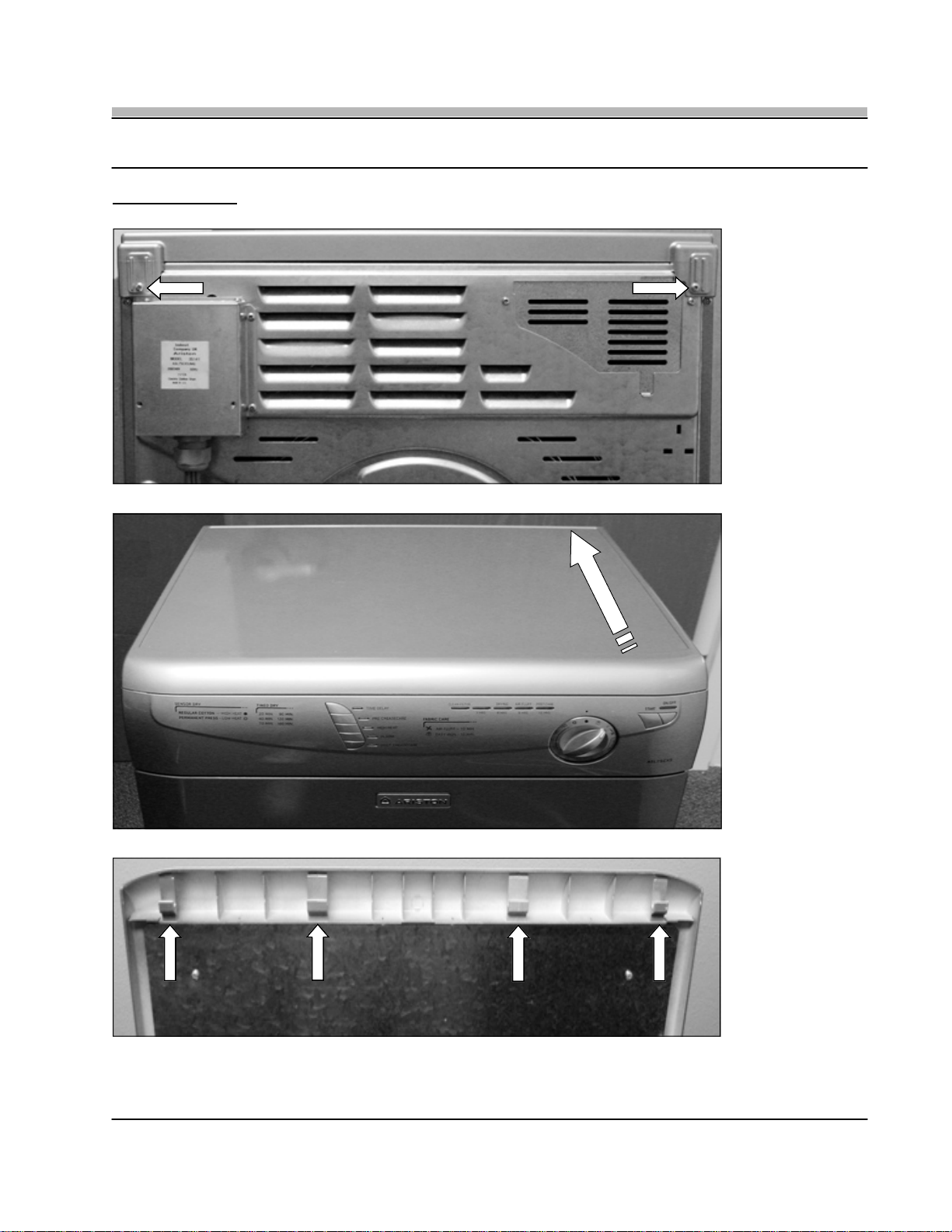
3. TOP PANEL
REPAIR MANUAL
ASL75CXS NA
Fig. 3-1
Fig. 3-2
Fig. 3-3
• To remove the Top Panel, first remove the two Phillips screws located at the rear corners of the panel (Fig. 3-1). With the two
screws removed slide the Rear Panel back and off the unit (Fig. 3-2). When reinstalling the Top Panel, Slide the Top Panel Clips
under the Control Panel and then replace the two Phillips Screws (Fig. 3-3).
Page: 3
Page 7

4. CONTROL PANEL
REPAIR MANUAL
Fig. 4-1
ASL75CXS NA
• To remove the Control Panel, first
remove the two Phillips screws located
on the top left and right corners
(Fig. 4-1).
• The Control Panel will then lift up and off
the four cut outs located on the inner
frame (Fig. 4-2).
• Disconnect the single wire harness
connection and the complete Control
Panel can be separated from the frame.
REAR VIEW
Fig. 4-2
5. CONTROL PANEL PROGRAM BOARD
Fig. 5-1
• To remove the Control Panel Program Board, first remove the Program Dial by carefully prying it out from the Control Panel making
sure not to damage the Dial or Control Panel (Fig. 5-1). Next, release the three Program Board locking tabs and removed Program
Board from the Control Panel (Fig. 5-2).
Fig. 5-2
Page: 4
Page 8

6. DOOR SWITCH
REPAIR MANUAL
ASL75CXS NA
• To remove the Door Switch (Fig. 6-1),
first remove the Control Panel (see
Section 4, page 4).
• Then push down on the locking tab and
lift the door switch from the frame cut
out (Fig. 6-2).
TECH NOTE: The Door Switch can be
removed and installed easier with the Door
Panel in the open position.
Fig. 6-1
7. CONDENSATION UNIT
Fig. 7-1
Fig. 6-2
Fig. 7-2
• The Condensation Unit is located behind the Lower Access Door. To remove the Condensation Unit turn the three locking clips to
the open position (Fig. 7-1) and the complete Condensation Unit can be removed by pulling it forward (Fig. 7-2).
TECH NOTE: For best performance and operation the Condensation Unit should be cleaned once each month.
Page: 5
Page 9

8. HEATER ASSEMBLY
REPAIR MANUAL
TECH NOTE 1
Fig. 8-1
ASL75CXS NA
• To access the Heater Assembly and Rear Thermostats,
remove the nine Heater Housing Phillips Screws (Fig. 8-1).
• The Heater Housing will come clear of the Rear Panel, but
it will still be attached to the wire harness (Fig. 8-2).
• The Heating Element Assembly is attached to the Heater
Housing with two Phillips screws. To remove the Heating
Element from the Heater Housing remove these two
screws (Fig. 8-3). See TECH NOTE on Fig. 8-1 for Heating
Element screw locations.
• The Heating Element Assembly contains both an upper
and lower element with a total output of 2500w along with
two Thermostats, see Section 9, Page 7 for Thermostat
details.
• To access the wire harness disconnect for the Heater
Assembly, it will be necessary to remove the Right Side
Panel (See Section 10, Page 10).
TECH NOTE 1: The two Heating Element Assembly screws
DO NOT
Housing.
have to be removed when removing the Heater
Fig. 8-2
Fig. 8-3
Page: 6
Page 10

REPAIR MANUAL
9. THERMISTOR & HIGH LIMIT - REAR
ASL75CXS NA
HIGH LIMIT
THERMISTER
Fig. 9-1
• There are two temperature sensing devises located on the Heating Element Assembly Figures 9-1 and 9-2.
• HIGH LIMI T: The High Limit Thermostat (white) is a One-Shot Cut Out (143˚f) Non-resetable.
• THERMISTOR (Rear): The Rear Thermistor (black) cycles the Heating Elements as necessary to maintain temperature. The Rear
Thermister measures inlet air temperature and communicates this information back to the Control Board.
TECH NOTE: The Thermistor has a value of approximately 500k Ohms at room temperature.
9. THERMISTOR - FRONT
• The Front Thermistor is located just behind the Control Panel to the right of the Door Switch (Fig. 9-3). The Front Thermistor
measures exhaust air temperature and communicates this information to the Control Board.
TECH NOTE: The Thermistor has a value of approximately 500k Ohms at room temperature.
Fig. 9-2
Fig. 9-3
Page: 7
Page 11

REPAIR MANUAL
10. RIGHT SIDE PANEL & COMPONENTS
ASL75CXS NA
Fig. 10-1
• To remove the Right Side Panel, first remove the Top Panel (see Section 4, page 4), then remove the five Phillips screws, one on
top, and four along the back edge (Fig. 10-1). The Side Panel will then slide back and off the unit (Fig. 10-2).
Fig. 10-2
B
A
C
Fig. 10-3
• With the Right Side Panel removed you have access to the following components (Fig. 10-3)
- A - Control Board and EEPROM Chip.
- B - Front Fan Housing and Fan.
- C - Motor Assembly (Motor, Capacitor, Tension Roller).
Page: 8
Page 12

REPAIR MANUAL
11. CONTROL BOARD & EEPROM
ASL75CXS NA
• To remove the Control Panel (Fig. 11-1), first remove the
Right Side Panel (see Section 10, page 8).
• Next, open the Front Lower Access Door and remove the two
Control Board mounting Phillips screws (Fig.11-2 & Fig.11-3).
• Remove each wiring connector, making sure to note each
wire and wiring connector location.
TECH NOTE 1: The access cap on the control board WILL NOT
have to be removed to remove the Control Board (Fig. 11-3).
Fig. 11-1
TECH NOTE 2
Fig. 11-2
Fig. 11-4
TECH NOTE 1
Fig. 11-3
TECH NOTE 2: When replacing the Control Board you must
also replace the EEPROM Chip. When ordering the replacement Control Board make sure to also order the correct
EEPROM Chip for the Model being serviced (Fig. 11-4).
• When installing the new EEPROM Chip make sure that
both the Chip Cut Out and the Chip Receptacle Cut Out
are aligned in the same direction (Fig. 11-5).
Fig. 11-5
Page: 9
Page 13

12. MOTOR REPLACEMENT
TECH NOTE
REPAIR MANUAL
• To remove the Motor (Fig. 12-1), first remove the Right Side
Panel (see Section 10, page 8) and the Control Board (see
Section 11, Page 9, Fig 11-2 & 11-3).
TECH NOTE: Only the Control Board mounting screws need to be
removed so that the Control Board can be moved out of your way,
the wiring does not have to be removed and can remain
connected.
• Next, using a flat bladed screwdriver remove the Front Fan
Cover by prying it out from its two mounting tabs (Fig. 12-2).
Fig. 12-1
The Fan Cover will then lift up and off.
• Then using a Needle Nose Pliers remove the Fan Blade Clamp,
and then slide the Fan Blade off the Motor Shaft (Fig. 12-3).
ASL75CXS NA
Fig. 12-2
Fig. 12-3
Fig. 12-4
Fig. 12-5
TECH NOTE: When reinstalling the Fan Cover
make sure to insert the Fan Cover Lip (Fig. 12-4)
into the slot on the base (Fig.12-5) and then lock
the Fan Cover back into position.
Page: 10
Page 14

REPAIR MANUAL
12. MOTOR REPLACEMENT Cont.
ASL75CXS NA
Fig. 12-6
• Next remove the rear Fan Blade by first removing the nine Phillips screws attaching the Heater Housing to the Rear Panel
(Fig. 12-6). Then remove the Fan Blade Clamp and slide the Rear Fan Blade from the Motor Shaft (Fig.12-7). Now remove the
four 8mm Motor Mounting Bolts and the Motor can be removed and replaced.
Fig. 12-7
Fig. 12-8
12. MOTOR INSTALLATION
TECH NOTE
Fig. 12-9
Fig. 12-10
TECH NOTE: With the Drum Belt loose, dry fit the new Motor and align the four Motor Mounting Bolt Screw Holes of the Motor with
the four rear bolt hole openings on the Base. Then mark both the Motor and the Motor Base with a reference line (Fig. 12-9). This will
make it easier to install the Motor and align the bolt holes and threads as you hold tension on the belt while inserting the four bolts.
• With your reference line in place, install the Belt around the Motor Shaft and Pulley. Now using a screwdriver tension the belt.
When your two reference lines are aligned insert one of the 8mm Motor Mounting Bolts and secure (Fig.12-10). Then install the
other three Mounting Bolts and reinstall all Motor Components and test.
Page: 11
Page 15

REPAIR MANUAL
13. DRUM BELT & BEARING BLOCK
ASL75CXS NA
• To remove Drum Belt (Fig. 13-1), first
remove the Top Panel (see Section 3,
page 3) and the Right Side Panel (see
Section 10, page 8).
• Then remove the two Phillips screws
that attach the Bearing Block Cover to
the Rear Panel (Fig. 13-2).
Fig. 13-1
Fig. 13-3
Fig. 13-2
Fig. 13-4
Fig. 13-5
• With the Bearing Block Cover removed, remove the two Phillips screws that attach the Drum Grounding Strip (Fig. 13-3). Then
using a Needle Nose Pliers remove the Drive Pin (Fig. 13-4).
TECH NOTE: Be careful not to damage the Drive Pin, since you will need to reuse it.
BEARING BLOCK: At this point the Bearing Block can be replaced if required.
• Then remove the Drum Belt from the Motor and Pulley Wheel (see Section 12, pages 10 & 11).
• Next, remove the Right Side Strut (Fig.13-5). Then separate the Rear Panel from the Drum and slide the Drum Belt off the Drum.
Page: 12
Page 16

14. DRAIN MOTOR
REPAIR MANUAL
ASL75CXS NA
Fig. 14-2
Fig. 14-1
Fig. 14-3
• The Drain Motor and Float Switch are located under the Drain Housing Cover (Fig. 14-1).
• To open the Drain Housing Cover insert a flat blade screwdriver behind each clip and unhook each latch (Fig. 14-2).
• The Float Switch is located on t he left, and the Drain Motor is located on the right. The Base Plate can be remo ved to access the
float by releasing the two locking clips (Fig. 14-3) and pulling the complete Base Plate up from the reservoir.
TECH NOTE: If the reservoir is full of water the Float Switch will disengage the Heating Element.
Page: 13
Page 17

REPAIR MANUAL
15. FAULT CODES ASL75CXS NA
ASL75CXS NA
Page: 14
Page 18

16. SCHEMATIC ASL75CXS NA
REPAIR MANUAL
ASL75CXS NA
Page: 15
 Loading...