


 Loading...
Operating and installation instructions
Electronic position indicator RI21
Contents
1.0 General information on operating |
2-2 |
|
instructions .................................................. |
||
2.0 Notes on possible dangers......................... |
2-2 |
|
2.1 |
Significance of Symbols ..................................... |
2-2 |
2.2 |
Explanatory notes on safety information.............. |
2-2 |
3.0 Storage and transport ................................. |
2-2 |
|
4.0 Description................................................... |
2-3 |
|
4.1 |
Scope of application............................................. |
2-3 |
4.2 |
Operating principle............................................... |
2-3 |
4.3 |
Technical data ...................................................... |
2-4 |
4.4 |
Dimensions .......................................................... |
2-4 |
5.0 Installation ................................................... |
2-5 |
|
5.1 |
General notes on installation................................ |
2-5 |
5.2 |
Installation in control cabinet................................ |
2-5 |
5.3 |
Installation in ARI-PREMIO actuator.................... |
2-6 |
5.4 |
Installation in CS25 to CS27 actuator .................. |
2-7 |
5.5 |
Electrical connection ............................................ |
2-8 |
5.5.1 Circuit diagram............................................... |
2-8 |
|
5.5.2 Terminal assignments .................................. |
2-9 |
|
5.5.3 Connection Conditions................................... |
2-9 |
|
5.6 |
Connection in Control Cabinet ............................. |
2-9 |
5.7 |
Connection in ARI-PREMIO (circuit diagram) .... |
2-10 |
5.7.1 ARI-PREMIO 2,2 - 5 kN ............................... |
2-10 |
|
5.7.2 ARI-PREMIO 12 - 15 kN without integrated |
|
|
|
reversing contactor ....................................... |
2-11 |
5.7.3 ARI-PREMIO 12 - 15 kN with integrated |
|
||
|
|
reversing contactor....................................... |
2-12 |
5.8 |
Connection in ARI-PREMIO (description) ......... |
2-13 |
|
5.9 |
Connection in CS25 to CS27 actuator |
|
|
|
|
(circuit diagram)................................................. |
2-14 |
5.10 Connection in CS25 to CS27 actuator |
|
||
|
|
(description)..................................................... |
2-15 |
6.0 |
Starting up ............................................... |
2-16 |
|
6.1 |
Factory setting................................................... |
2-17 |
|
6.2 |
Setting of potentiometer .................................... |
2-17 |
|
6.3 |
Type of control signal ........................................ |
2-18 |
|
6.4 |
Zero point setting ............................................. |
2-19 |
|
6.5 |
Slope span setting ............................................ |
2-20 |
|
7.0 |
Care and maintenance.............................. |
2-20 |
|
8.0 |
Troubleshooting........................................ |
2-21 |
|
9.0 |
Troubleshooting table .............................. |
2-21 |
|
10.0 Dismantling of the position indicator |
.. 2-22 |
||
11.0 Warranty / Guarantee .............................. |
2-22 |
||
12.0 EU declaration of conformity................. |
2-23 |
||
Rev. 0040602000 1014
Operating and installation instructions
Electronic position indicator RI21
1.0 General information on operating instructions
These operating instructions provide information on mounting and maintaining the fittings. Please contact the supplier or the manufacturer in case of problems which cannot be solved by reference to the operating instructions.
They are binding on the transport, storage, installation, start-up, operation, maintenance and repair.
The notes and warnings must be observed and adhered to.
-Handling and all work must be carried out by expert personnel or all activities must be supervised and checked.
It is the owner’s responsibility to define areas of responsibility and competence and to monitor the personnel.
-In addition, current regional safety requirements must be applied and observed when taking the fittings out of service as well as when maintaining and repairing them.
The manufacturer reserves the right to introduce technical modifications at any time. These Operating Instructions comply with the requirements of EU Directives.
2.0Notes on possible dangers
2.1Significance of Symbols
ATTENTION ! |
|
. . . |
Warning of general danger. |
|
|
|
|
ATTENTION ! |
|
. . . |
Warning of dangerous voltage. |
2.2 Explanatory notes on safety information
In these Operating and Installation Instructions dangers, risks and items of safety information are highlighted to attract special attention.
Information marked with the above symbol and “ATTENTION ! ” describe practices, a failure to comply with which can result in serious injury or danger of death for users or third parties or in material damage to the system or the environment. It is vital to comply with these practices and to monitor compliance.
All other information not specifically emphasised such as transport, installation, operating and maintenance instructions as well as technical data (in the operating instructions, product documentation and on the device itself) must also be complied with to the fullest extent in order to avoid faults which in turn can cause serious injury to persons or damage to property.
3.0 Storage and transport
-At -20° to +70°C dry, free from dirt.
-Do not unpack electronics prior to installation.
-Protect against external force (impact, vibration etc.).
-Do not soil or damage type identification plate and wiring diagram on the controller.
Page 2-2 |
Rev. 0040602000 1014 |
Operating and installation instructions
Electronic position indicator RI21
4.0Description
4.1Scope of application
The electronic position indicator RI21 is used for converting electrical resistances of up to
1000 to electrical signals.
The electronic position indicator RI21 is suitable for installation in switch cabinets as well as in the actuator ARI-Premio or in actuators ARI CS25 through CS27.
Electronic position indicators installed in an actuator serve to indicate exact positioning.
The ambient conditions have to be conform to the actual electromagnetic compatibility directives. Additional the compatibility to this directives has to be maintained in case of expansion or other changings of the ambient conditions.
4.2 Operating principle
The Ready Status on the electronic position indicator is indicated by a yellow LED.
The positioning signal is selected by means of the slide switch SY.
Matching of the resistance input and positioning signal output is effected via trimming potentiometers.
The positioning signal outputs Yu and Yi are dependent on set resistance value of the connected potentiometer.
The control section is (electrically) DC-decoupled from the mains input.
ATTENTION !
For use on a three-wire system, the ground input may only be connected up to the N contact of the mains input on the 24V AC version.
The new contact is referred to as zero potential (0V)
Rev. 0040602000 1014 |
Page 2-3 |
Operating and installation instructions
Electronic position indicator RI21
4.3 Technical data
Operating Voltage |
UB |
24V |
50-60Hz |
115V 50-60Hz |
230V |
50-60Hz |
|
|
-20% +10% |
-20% +10% |
-20% |
+10% |
|
Operating current |
IB |
150 mA |
40 mA |
20 mA |
||
Output positioning signal |
Yu |
0(2) |
... 10V DC |
(working resistance |
> 1000 ) |
|
Output positioning signal |
Yi |
0(4) |
... 20mA DC (working resistance < 800 ) |
|||
Potentiometer input |
Rp |
0....1000 (Tol. +30/-50%) |
|
|
||
Type of enclosure |
|
IP40 (clamps IP20) |
|
|
||
Ambient temperature |
|
-20....+70 °C |
|
|
|
|
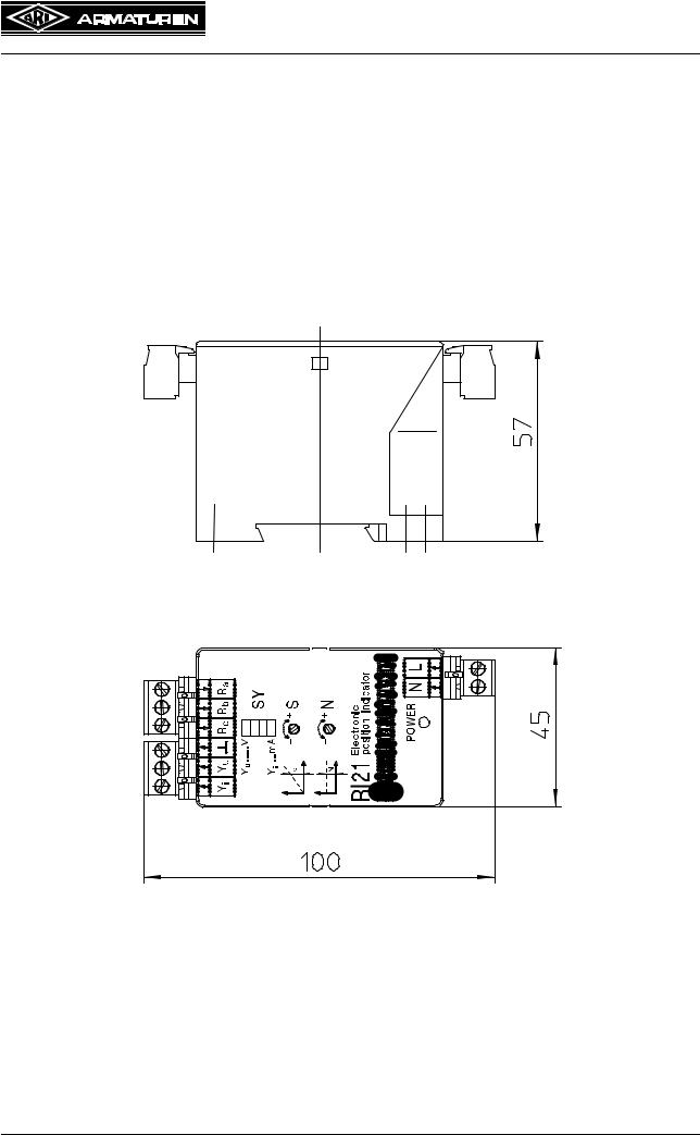
4.4 Dimensions
Fig. 1
Page 2-4 |
Rev. 0040602000 1014 |
Operating and installation instructions
Electronic position indicator RI21
5.0 Installation
ATTENTION !
Work on electrical systems or equipment must only be carried out by qualified electricians or by trained individuals under the guidance and supervision of a qualified electrician in compliance with regional electrical requirements and regulations.
When connecting electronics the supply line must be disconnected from the mains (not live) during connection work. Non-compliance may result in death, serious injury or substantial damage to property.
-The power supply and data provided on the type identification plate must agree.
-Do not touch live parts when carrying out adjustments.
-Take particular caution at voltages above 24 V!
-Do not disconnect or connect series isolating terminals with the power on!
-Ground connection between N and is only permitted in the 24 V version.
-Only one actuator is to be connected at any one time.
-Do not overshoot the range of the actuator when carrying out adjustments, danger of damage.
-Ensure that the motor connected in the actuator switches off in the end positions based on distance or torque.
5.1General notes on installation
The electronic position indicator RI21 can be installed in a switch cabinet or in the actuator
ARI-PREMIO as well as in actuators CS25 through CS27.
Retrofitting of the electronic position indicator RI21 is possible on the ARI-PREMIO actuator.
On actuators CS25 through CS27 retrofitting of the electronic position indicator RI21 is conditional.
Please address all technical queries direct to ARI-ARMATUREN.
-Regional electrical requirements and regulations must be observed when laying electricity lines and making electrical connections.
-The cable cross-section must always correspond to the relevant input current and the cable length.
-The rated mains voltage and mains frequency must agree with the data on the type identification plate.
Mains power fuse protection, installation side: 6 A max.
5.2 Installation in control cabinet
-The controller is mounted on a profile rail in the control cabinet in accordance with DIN
46277.
-The mounting grid for control panel installation is L 58 mm x W 35 mm.
Installation parts:
- 1 electronic position indicator RI21
Rev. 0040602000 1014 |
Page 2-5 |

Operating and installation instructions
Electronic position indicator RI21
5.3 Installation in ARI-PREMIO actuator
Refer to figures below for installation in ARI-PREMIO actuator.
C
B |
A |
Fig. 2: Installation RI21 / ES11 ARI-PREMIO 2,2 - 15 kN
Installation procedure:
Carefully remove cover.
AFit mounting bracket (50.80) at point on gear cover provided for this purpose.
Secure with two socket head cap screws (50.81) DIN EN ISO 4762 - M4x8.
B/C Secure the electronic position indicator RI21 (50.78/79) with two socket head cap screws (50.82) DIN EN ISO 4762 - M4x12 on mounting bracket (50.80).
ATTERNTION !
For potentiometer installation, refer to ARI-PREMIO operating instructions
Installation parts:
-1 electronic position indicator RI21
-1 Mounting bracket ES11/RI21
-2 Socket head cap screws DIN EN ISO 4762 - M4x8
-2 Socket head cap screws DIN EN ISO 4762 - M4x12
-1 1000 Ohm potentiometer
-1 Potentiometer cable
-2 PT screws KB 22x8 WN1412-Zi
-1 Sliding block
-1 Torsion spring
-1 Washer
-1 Spur gear
Page 2-6

Operating and installation instructions
Electronic position indicator RI21
5.4 Installation in CS25 to CS27 actuator
Refer to figure below for installation in CS25 to CS27 actuator.
Fig. 3
Installation procedure:
-Carefully remove cover.
-Loosen capacitor, for this purpose, release corresponding cable ties.
-Secure capacitor plate with screw DIN EN ISO 4762 - M8x10 on to gearbox cover.
-Install capacitor on capacitor plate
-Secure mounting bracket on gearbox cover with two self-tapping screws DIN7500 - M4x8.
-Secure RI21 to mounting bracket with two socket head cap screws DIN EN ISO 4762 - M4x12.
-Tie together newly installed cables with cable ties.
-Remove old circuit diagrams from cover and affix new circuit diagram in cover.
ATTENTION !
For potentiometer installation, refer to operating instructions for CS actuators.
Mounting parts:
-1 electronic position indicator RI21
-1 Mounting bracket ES11/RI21
-2 Socket head cap screws DIN EN ISO 4762 - M4x12
-1 Socket head cap screws DIN EN ISO 4762 - M8x10
-1 Capacitor plate
-2 Self-tapping screws DIN 7500 - M4x8
-1 1000 Ohm potentiometer, soldered
-2 Lock rings for potentiometer
-1 Pinion for potentiometer
-1 CS electronic position indicator cable
-1 Circuit diagram RI21 + CS25
-2 Cable ties
Rev. 0040602000 1014 |
Page 2-7 |
Loading...