


 Loading...
Operating and Installation Instructions
Thrust actuator
ARI-PREMIO-Plus
|
Contents |
|
1.0 General information on operating instructions...................................................................................... |
3 |
|
2.0 Notes on possible dangers ...................................................................................................................... |
3 |
|
2.1 |
Significance of symbols .................................................................................................................... |
3 |
2.2 |
Explanatory notes on safety information............................................................................................ |
4 |
3.0 Storage and transport............................................................................................................................... |
4 |
|
4.0 Description ................................................................................................................................................ |
5 |
|
4.1 |
Field of application ............................................................................................................................. |
5 |
4.2 |
Method of functioning......................................................................................................................... |
5 |
4.3 |
Diagram ............................................................................................................................................. |
6 |
|
4.3.1 ARI-PREMIO 2,2 - 5 kN............................................................................................................ |
6 |
|
4.3.2 ARI-PREMIO 12 - 15 kN........................................................................................................... |
7 |
|
4.3.3 Parts list .................................................................................................................................... |
8 |
4.4 |
Technical data .................................................................................................................................... |
9 |
4.5 |
Interface description......................................................................................................................... |
10 |
|
4.5.1 Control - Run commands........................................................................................................ |
10 |
|
4.5.2 Feedback ................................................................................................................................ |
11 |
|
4.5.3 Design notes........................................................................................................................... |
12 |
|
4.5.3.1 Control signal ............................................................................................................................. |
12 |
|
4.5.3.2 Behavior in control signal failure / error...................................................................................... |
12 |
|
4.5.3.3 Analog feedback signal .............................................................................................................. |
12 |
|
4.5.3.4 dTRON 316 ................................................................................................................................ |
13 |
4.6 |
Dimensions ...................................................................................................................................... |
14 |
Rev. 0040501004 5010 englisch
5.0 Installation .............................................................................................................................................. |
15 |
|
5.1 |
General installation data .................................................................................................................. |
15 |
5.2 |
Manual operation ............................................................................................................................ |
17 |
|
5.2.1 ARI-PREMIO 2.2 - 5 kN ......................................................................................................... |
17 |
|
5.2.2 ARI-PREMIO 12 - 15 kN......................................................................................................... |
17 |
5.3 |
Installation instructions for mounting to valves ................................................................................ |
18 |
|
5.3.1 Mounting for valve-lift up to 30 mm (yoke version) ................................................................ |
18 |
|
5.3.2 Mounting for valve lift over 30 mm to 65 mm (column version) ............................................. |
20 |
|
5.3.3 Setting dimensions for guiding stem ..................................................................................... |
22 |
5.4 |
Electrical connection ........................................................................................................................ |
23 |
|
5.4.1 Wiring diagram ARI-PREMIO 2.2 - 15 kN............................................................................... |
23 |
|
5.4.2 Wiring diagram ARI-PREMIO 12 - 15 kN 3 Ph~ without reversing contactor ......................... |
24 |
|
5.4.3 Connection.............................................................................................................................. |
25 |
5.5 |
Settings - Handling .......................................................................................................................... |
26 |
|
5.5.1 Display and operating elements of the standard electronics ................................................. |
26 |
|
5.5.2 LEDs ....................................................................................................................................... |
27 |
|
5.5.3 Switch functions ..................................................................................................................... |
27 |
5.6 |
Special functions.............................................................................................................................. |
30 |
|
5.6.1 Economy – Wear reduction program ...................................................................................... |
30 |
|
5.6.2 Cyclic operation after a reset or when the power is returned after a power failure................. |
30 |
|
5.6.3 Adaptive hysteresis band........................................................................................................ |
30 |
|
5.6.4 Temperature management...................................................................................................... |
31 |
|
5.6.5 Condensation on the printed circuit board .............................................................................. |
31 |
|
5.6.6 "Yin" signal failure ................................................................................................................... |
31 |
|
5.6.7 Characteristics ....................................................................................................................... |
32 |
|
5.6.8 Double control at the 3-point input......................................................................................... |
32 |
|
5.6.9 Priorities.................................................................................................................................. |
32 |
5.7 |
Options ............................................................................................................................................ |
33 |
|
5.7.1 Relay card............................................................................................................................... |
33 |
|
5.7.1.1 Operating principle ..................................................................................................................... |
33 |
|
5.7.1.2 Technical data............................................................................................................................. |
34 |
|
5.7.1.3 Installation procedure ................................................................................................................. |
34 |
|
5.7.1.4 Electrical connection .................................................................................................................. |
34 |
|
5.7.1.5 Operation – Programming / clearing positions .......................................................................... |
35 |
|
5.7.2 Analogue output card – Yout................................................................................................... |
36 |
|
5.7.2.1 Operating principle ..................................................................................................................... |
36 |
|
5.7.2.2 Technical data............................................................................................................................. |
36 |
|
5.7.2.3 Installation procedure ................................................................................................................. |
37 |
|
5.7.2.4 Electrical connection .................................................................................................................. |
37 |
|
5.7.3 Heating ................................................................................................................................... |
38 |
|
5.7.3.1 Installation of heating.................................................................................................................. |
38 |
|
5.7.4 Integrated temperature controller dTRON 316 ....................................................................... |
39 |
|
5.7.4.1 Installation of the dTRON 316 .................................................................................................... |
39 |
6.0 Putting the actuator into operation ...................................................................................................... |
40 |
|
6.1 |
Configuring the control signal .......................................................................................................... |
40 |
6.2 |
Connecting the supply voltage......................................................................................................... |
41 |
6.3 |
Initialisation ................................................................................................................................... |
41 |
7.0 Care and maintenance ........................................................................................................................... |
42 |
|
8.0 Troubleshooting...................................................................................................................................... |
42 |
|
9.0 Troubleshooting table ............................................................................................................................ |
43 |
|
9.1 |
Failure signals according to NAMUR NE 107 .................................................................................. |
44 |
9.2 |
LED encoding (from software version 2.1.7 and higher).................................................................. |
46 |
10.0 Dismantlement of thrust actuator ....................................................................................................... |
46 |
|
11.0 Warranty / Guarantee ............................................................................................................................ |
47 |
|
12.0 EC declaration of conformity............................................................................................................... |
48 |
|

Operating and installation instructions
Thrust actuator ARI-PREMIO-Plus
1.0 General information on operating instructions
These operating instructions provide information on mounting, handling and maintaining the thrust actuators. Please contact the supplier or the manufacturer in case of problems which cannot be solved by reference to the operating instructions.
They are binding on the transport, storage, installation, start-up, operation, maintenance and repair.
The notes and warnings must be observed and adhered to.
-Handling and all work must be carried out by expert personnel or all activities must be supervised and checked.
It is the owner’s responsibility to define areas of responsibility and competence and to monitor the personnel.
-In addition, current regional safety requirements must be applied and observed when taking the fittings out of service as well as when maintaining and repairing them.
The manufacturer reserves the right to introduce technical modifications at any time.
These Operating Instructions comply with the requirements of EU Directives.
2.0Notes on possible dangers
2.1Significance of symbols
ATTENTION !
. . .
ATTENTION !
. . .
NOTE !
. . .
Warning of general danger.
Warning of dangerous voltage.
General information.
Exposed to injury!
Don’t touch the turning handwheel when the motor is running.
Exposed to injury!
Don’t put your hand into the up or downwards moving appliance.
Danger when not observing the operating and installation instructions!
Before installing, operating, maintenance or dismantling read and observe the instructions.
Danger though voltage!
Before dismantling the hood, switch of the electrical source and secure against turning on again.
0040501004 5010 |
Page 3 |
Operating and installation instructions
Thrust actuator ARI-PREMIO-Plus
2.2 Explanatory notes on safety information
In these Operating and Installation Instructions dangers, risks and items of safety information are highlighted to attract special attention.
Information marked with the above symbol and “ATTENTION ! ” describe practices, a failure to comply with which can result in serious injury or danger of death for users or third parties or in material damage to the system or the environment. It is vital to comply with these practices and to monitor compliance.
All other information not specifically emphasised such as transport, installation, operating and maintenance instructions as well as technical data (in the operating instructions, product documentation and on the device itself) must also be complied with to the fullest extent in order to avoid faults which in turn can cause serious injury to persons or damage to property.
3.0 Storage and transport
ATTENTION !
- Valve mountings such as drives, handwheels, hoods must not be used to take external forces, e.g. they are not designed for use as climbing aids, or as connecting points for lifting gear.
Non-compliance may lead to death, injury or damage to property due to persons falling or parts being dropped.
-Suitable materials handling and lifting equipment should be used. See “4.4 Technical data” for weights.
-At -40°C to +85°C dry, free from dirt.
-Do not unpack thrust drive or setting equipment assembly prior to installation.
-Protect against external force (impact, vibration etc.).
-Do not soil or damage type identification plate and wiring diagram on the controller.
Page 4 |
0040501004 5010 |

Operating and installation instructions
Thrust actuator ARI-PREMIO-Plus
4.0Description
4.1Field of application
ARI-PREMIO linear thrust actuators are employed to actuate control or shut-off valves requiring a nominal linear stroke distance.
The intelligent PREMIO-Plus thrust actuator is used whenever the actuator is controlled with an analogue signal (0 to 10 V / 4 to 20 mA) or a 3-point signal and feedback information about positions, operating states, faults, etc. has to be output.
If supplied with the valve, the lift of the thrust actuator will be set to the stroke distance of the valve.
Selection of the proper actuator version in alignment with the corresponding fitting as well as use of the thrust actuator in accordance with the specified technical data is the responsibility of the systems engineer.
See data sheet for areas of application, application limits and potential.
Any use of the thrust actuator beyond the specified technical data or improper use of the actuator is deemed to be not for the intended purpose.
The ambient conditions have to be conform to the actual electromagnetic compatibility directives. Additional the compatibility to this directives has to be maintained in case of expansion or other changing of the ambient conditions.
4.2 Method of functioning
The eight parameter switches allow the PREMIO-Plus thrust actuator to be adapted to a variety of situations without a PC or tools. The electronics are likewise suitable for use in a wide range of supply and signalling systems.
The motor and spindle can be moved up and down in manual mode by means of the  and
and
 switch positions.
The valve final positions and the type of control (3-point or analogue) are automatically determined by the electronics in an initialisation run. An analogue signal must be present at the input during the initialisation run for analogue control.
The desired position can be specified by means of the analogue control input. The input is protected against polarity reversal. It can be configured as a current (4 to 20 mA) or voltage
(0 to 10 V) input using a switch.
Two binary control inputs are provided for the 3-point signal. These inputs are designed for a wide operating range with voltages from 12 V AC/DC to 250 V AC/DC.
The 3-point control signal takes priority over the analogue input signal, e.g. for fail-safe or anti-freeze protection. If a signal is present at both inputs (double control), the control mode is interrupted.
The spindle position is determined by means of non-contacting and non-wearing reflex sensors.
The motor output stage operates the connected AC motor by means of two triac switching stages with a 3-point control signal. This stage is electrically isolated from the control electronics by opto-decoupled drivers. A zero voltage switch controls the triacs in order to restrict emissions to a minimum.
The actual position (position feedback) is output via the analogue output (optional). The output signal is configured as a current or voltage output using the same switch as for the analogue input signal. The output is electrically isolated.
0040501004 5010 |
Page 5 |

Operating and installation instructions
Thrust actuator ARI-PREMIO-Plus
Four unassigned relay outputs can be optionally supplied for alarm signals and connection to 24 V to 250 V DC/AC voltage. By using gold-plated contacts, it is possible to switch both binary inputs with a low operational current and switching currents up to 2 A. With 250 V AC operation, the gold plating can be burned off once without any negative effects on this connection type.
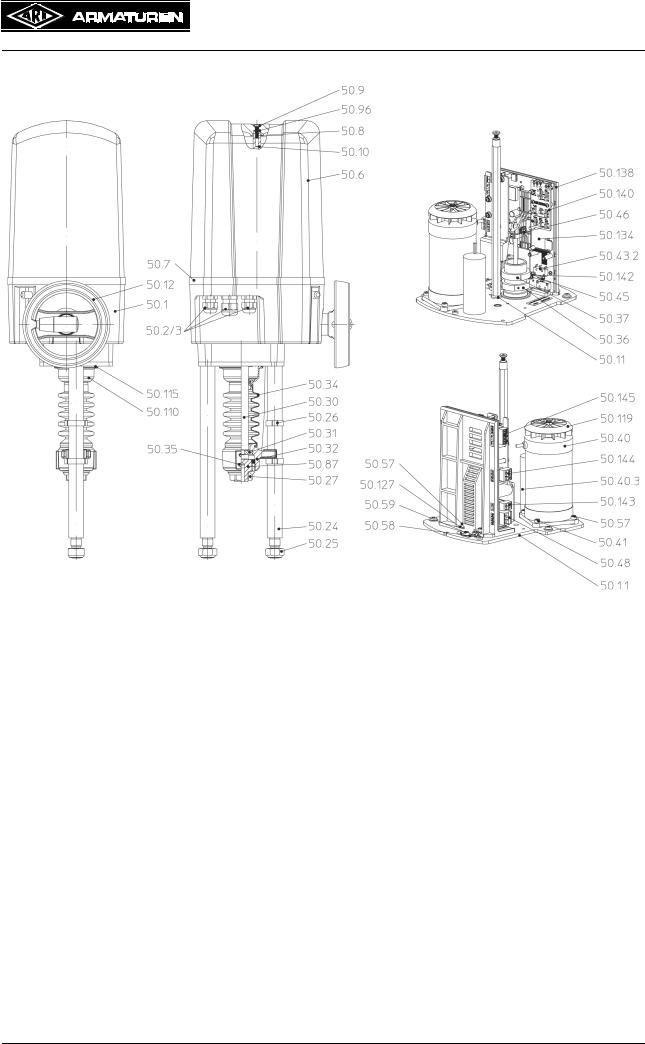
4.3 Diagram
4.3.1 ARI-PREMIO 2,2 - 5 kN
Yoke Version |
Column Version |
Fig. 1
Page 6 |
0040501004 5010 |
Operating and installation instructions
Thrust actuator ARI-PREMIO-Plus
4.3.2 ARI-PREMIO 12 - 15 kN
Fig. 2
0040501004 5010 |
Page 7 |

Operating and installation instructions
Thrust actuator ARI-PREMIO-Plus
4.3.3 Parts list
Pos. |
Designation |
|
Pos. |
Designation |
50.1 |
Gearbox |
|
50.36 |
Set collar |
|
|
|
|
|
50.1.1 |
Gearbox cover plate |
|
50.37 |
Grub screw DIN 913-M3x5 |
|
|
|
|
|
50.2 |
Cable gland 2 x M16x1.5 |
|
50.38 |
Guiding spindle |
|
|
|
|
|
50.3 |
Blind disc |
|
50.39 |
Hexagon nut DIN EN24034-M5 |
|
|
|
|
|
50.4 |
Sealing plug 1 x M16x1,5 |
|
50.40 |
Synchronous motor, complete |
|
|
|
|
|
50.6 |
Hood |
|
50.40.3 |
Motor capacitor |
|
|
|
|
|
50.7 |
Hood seal |
|
50.41 |
Head cap screw |
|
|
|
|
DIN EN ISO 4762-M4 - 18 |
|
|
|
|
|
50.8 |
Counter-sunk screw DIN EN ISO |
|
50.43.2 |
Torque switch |
|
10642 - M5x20 |
|
|
|
50.9 |
Sealing washer DIN EN ISO 7089 - |
|
50.45 |
Shift lever |
|
5,3 |
|
|
|
|
|
|
|
|
50.10 |
Column |
|
50.46 |
Washer |
|
|
|
|
|
50.11 |
Conical spring washer |
|
50.48 |
Connector, 3-pole (standard) |
|
|
|
|
|
50.12 |
Handwheel |
|
50.57 |
Head cap screw |
|
|
|
|
DIN EN ISO 4762 - M4x10 |
50.14 |
Yoke |
|
50.58 |
Protective conductor terminal |
|
|
|
|
|
50.16 |
Spring washer DIN 128-A10 |
|
50.59 |
Head cap screw |
|
|
|
|
DIN EN ISO 4762 - M4x6 |
50.17 |
Hexagon head screw |
|
50.87 |
Threaded bush |
|
DIN EN ISO 4017 - M10x40 |
|
|
|
|
|
|
|
|
50.19 |
T-head bolt DIN 261-M12x40 |
|
50.96 |
O-ring DIN 3771 – 4 x 1.8 |
|
|
|
|
|
50.20 |
Washer DIN EN ISO 7089 |
|
50.119 |
Fan wheel |
|
|
|
|
|
50.21 |
Spring washer DIN 128-A12 |
|
50.127 |
Washer ISO 7093-1 |
|
|
|
|
|
50.22 |
Hexagon nut DIN EN ISO 4032 - M12 |
|
50.128 |
Sealing nut M6 |
|
|
|
|
|
50.23 |
Lift dial |
|
50.130 |
Manual operating device SW17 |
|
|
|
|
|
50.24 |
Distance column |
|
50.134 |
Actuator control |
|
|
|
|
|
50.25 |
Hexagon nut DIN 980-V-M16 |
|
50.138 |
Board support |
|
|
|
|
|
50.26 |
2-ear clamp (stroke indicator) |
|
50.139 |
Protective cover |
|
|
|
|
|
50.27 |
Coupling |
|
50.140 |
Switch cover |
|
|
|
|
|
50.29 |
O-ring |
|
50.141 |
Trip slide |
|
|
|
|
|
50.30 |
Driving spindle |
|
50.142 |
Shakeproof washer |
|
|
|
|
|
50.31 |
Spindle safety feature |
|
50.143 |
Connector, 2-pole (N/L) |
|
|
|
|
|
50.32 |
Torsion safety feature |
|
50.144 |
Connector, 3-pole (0V / L↓ / L↑) |
|
|
|
|
|
50.34 |
Bellow |
|
50.145 |
Connector, 6-pole (63 / 64 / Yin / Yout) |
|
|
|
|
|
50.35 |
Grub screw DIN ISO 4766 - M6 |
|
|
|
|
|
|
|
|
Page 8 |
0040501004 5010 |

Operating and installation instructions
Thrust actuator ARI-PREMIO-Plus
4.4 Technical data
Type |
|
|
|
|
|
|
ARI-PREMIO |
|
|
|
|
|||||
Thrust force |
kN |
2,2 |
|
|
5,0 |
|
|
|
12,0 |
|
15,0 |
|||||
|
|
|
|
|
|
|
|
|
|
|
|
|
|
|
|
|
Stroke distance max. |
mm |
|
|
|
50 |
|
|
|
|
|
|
|
|
65 |
|
|
Duty classification acc. to EN 60034-1/A11 |
S3 80% DC/ max. 1200 c/h |
|
|
|
S3 50% DC / max. 1200 c/h |
|||||||||||
|
|
|
|
|
|
|
|
|
|
|
|
|
|
|
|
|
Control speed |
mm/sec. |
0.38 |
|
|
|
1.0 |
|
0.38 |
|
0.79 |
|
0.38 |
||||
Motor voltage |
|
|
230V - 50Hz / 60Hz |
1) |
|
|
|
|
|
230V - 50Hz |
||||||
|
|
|
|
|
|
|
|
|
|
|
|
|
|
|
|
|
Power consumption |
W |
24 |
|
|
37 |
|
|
94 |
|
112 |
|
|
133 |
|||
|
|
|
For |
power consumption |
of other voltages and frequencies |
|||||||||||
|
|
|
|
|
refer to type plate or on request. |
|
|
|
|
|||||||
Enclosure |
EN 60529 |
|
|
|
|
|
IP 65 |
|
|
|
|
|
|
|
||
|
|
|
|
|
|
|
|
|
|
|
|
|
|
|
||
Max. permissible storage temperature |
|
|
|
|
-40 °C |
... +85 °C |
|
|
|
|
||||||
Max. permissible ambient temperature |
|
|
|
|
-20 °C |
... +70 °C |
|
|
|
|
||||||
|
|
|
|
|
|
|
|
|
|
|
|
|
|
|||
Manual operating device |
|
Yes (rotating during operation) |
|
|
|
Yes (engageable) |
||||||||||
Operation |
|
|
|
|
|
|
Optionally:· |
|
|
|
|
|
|
|||
|
|
|
|
|
3-point: 12 V DC/AC to 250 V DC/AC· |
|
|
|
|
|||||||
|
|
|
0 to 10 V DC load resistance 470 kohm resolution 10 bit· |
|||||||||||||
|
|
|
4 to 20 mA DC load resistance 125 ohm resolution 10 bit |
|||||||||||||
|
|
|
|
|
|
|
|
|
|
|
|
|
|
|
||
Switching current |
|
|
|
|
|
Max. 4 A triac output |
|
|
|
|
||||||
Input for temperature sensor |
|
|
|
|
|
Sensor: PT1000 |
|
|
|
|
||||||
|
|
|
|
|
|
|
|
|
|
|
|
|
|
|
|
|
Max. cable cross section |
|
|
|
|
|
Supply voltage: |
2.5 mm² |
|
|
|
|
|||||
|
|
|
|
|
|
3-point input: 2.5 mm² |
|
|
|
|
||||||
|
|
|
|
|
|
Control signals: 1.5 mm² |
|
|
|
|
||||||
Mounting position |
|
|
Any. Exception: motor must not be suspended downwards |
|||||||||||||
|
|
|
|
|
|
|
|
|
|
|
|
|
|
|
|
|
Gear lubricant |
|
Klüber Isoflex Topas NB152 |
|
|
|
|
|
Molyduval |
||||||||
|
|
|
|
|
|
|
Valenzia H2 |
|||||||||
|
|
|
|
|
|
|
|
|
|
|
|
|
||||
Weight |
kg |
5,4 |
|
|
6,0 |
|
|
6,5 |
|
|
|
|
10,5 |
|
||
|
|
|
|
|
|
|
|
|
|
|
|
|
|
|
||
1) Control speed and power consumption are 20% higher at frequency of 60 Hz |
|
|
|
|
|
|
|
|
|
|||||||
Accessories |
|
|
|
|
|
|
|
|
|
|
|
|
|
|
|
|
|
|
|
|
|
|
|
|
|
|
|
|
|
|
|
||
Type |
|
|
|
|
|
|
ARI-PREMIO |
|
|
|
|
|||||
Thrust force |
kN |
2,2 |
|
|
5,0 |
|
|
|
12,0 |
|
|
|
|
15,0 |
||
Electronic position indicator |
|
|
Analogue output 4-20 mA, |
switchable to 0-10 V (invertable) |
|
|||||||||||
Relay board |
|
- 2 intermediate positions, settable with a switch, changeover contact 230 V AC 6A/3A, |
||||||||||||||
|
- 1 failure signal and 1 warning signal, changeover contacts 30V DC / 2A |
|||||||||||||||
|
|
|||||||||||||||
Heating resistor |
|
230 V 50/60 Hz 1), 115 V 50/60 Hz 1), 24 V 50/60 Hz 1), 15 W |
||||||||||||||
|
|
|
|
|
|
24V - 50Hz |
|
|
|
24V - 50Hz / 24V - 60Hz 1) |
||||||
Other voltages/ frequencies |
|
24V - 50/60Hz 1) |
|
24V - 60Hz 1) |
|
|
115V - 50Hz / 115V - 60Hz 1) |
|||||||||
|
115V - 50/60Hz 1) |
|
115V - 50/ |
|
|
|
230V - 60Hz 1) |
|||||||||
|
|
|
|
|
|
|||||||||||
|
|
|
|
|
|
60Hz 1) |
|
|
3~400V - 50Hz / 3~400V - 60Hz 1) |
|||||||
|
|
Three-step temperature-controller in microprocessor-technology. |
||||||||||||||
Integrated temperature-controller |
|
Control range: -200°C to 850°C (resistance thermometer) |
||||||||||||||
|
|
|
Voltage: 24V, 115V or 230V 50/60Hz |
|
|
|
|
|||||||||
dTRON 316 |
|
|
|
|
|
|
|
|
||||||||
|
Compatible with resistance thermometers and thermocouples |
|||||||||||||||
|
|
|||||||||||||||
|
|
(provided by customer), or standardized active current or voltage signals |
||||||||||||||
Integrated tempertaure controller dTRON |
Controler incl. PROFIBUS-DP-interface and analogue input card, 24 V, 115 V or 230 V 50/ |
|||||||||||||||
316 / PROFIBUS-DP |
|
60 Hz. Controlling via bus line (must be supplied by the customer). |
||||||||||||||
1) Control speed and power consumption are 20% higher at frequency of 60 Hz
0040501004 5010 |
Page 9 |

Operating and installation instructions
Thrust actuator ARI-PREMIO-Plus
4.5 Interface description
4.5.1 Control - Run commands
Control |
Desciption - Technical data |
Required options |
|
|
|
OPEN-STOP-CLOSE |
2 Binary input |
- |
(3-point) |
- 12V to 240V AC |
|
|
- zero potential contacts |
|
|
|
|
|
Modbus |
- dTRON316 |
|
- Protocol: Modbus, Modbus-integer |
with RS422/485 card |
|
- Baud rate: 9600, 19200, 38400 |
(dTRON options) |
|
- Device adress: 0 ... 255 |
|
|
- Max. number of participants: 32 |
|
|
|
|
|
Profibus-DP |
- dTRON316 |
|
- Device adress: 0 ... 255 |
with Profibus card (dTRON options) |
|
|
|
Set point control for |
4-20mA DC |
- |
position controller |
- Burden 125 Ohm |
|
|
- Resolution 10 Bit |
|
|
- Electrically isolated |
|
|
|
|
|
0-10V DC |
- |
|
- Burden 470 kOhm |
|
|
- Resolution 10 Bit |
|
|
- Electrically isolated |
|
|
|
|
|
Modbus |
- dTRON316 |
|
- Protocol: Modbus, Modbus-integer |
with analog output card and RS422/485 |
|
- Baud rate: 9600, 19200, 38400 |
card (dTRON options) |
|
- Device adress: 0 ... 255 |
|
|
- Max. number of participants: 32 |
|
|
|
|
|
Profibus-DP |
- dTRON316 |
|
- Device adress: 0 ... 255 |
with analog output card and Profibus |
|
|
card (dTRON options) |
|
|
|
Set point control for PID |
4-20mA DC |
- dTRON316 |
process control (Option |
- Burden 75 Ohm |
with analog output card and analog |
dTRON 316) |
- Resolution 10Bit |
input card (dTRON options) |
|
|
|
|
0-10V DC |
- dTRON316 |
|
- Burden > 100 kOhm |
with analog output card and analog |
|
- Resolution 10 Bit |
input card (dTRON options) |
|
|
|
|
Modbus |
- dTRON316 |
|
- Protocol: Modbus, Modbus-integer |
with analog output card and RS422/485 |
|
- Baud rate: 9600, 19200, 38400 |
card (dTRON options) |
|
- Device adress: 0 ... 255 |
|
|
- Max. number of participants: 32 |
|
|
|
|
|
Profibus-DP |
- dTRON316 |
|
- Device adress: 0 ... 255 |
with analog output card and Profibus |
|
|
card (dTRON options) |
|
|
|
Page 10 |
0040501004 5010 |
|
|
|
|
|
|
|
|
|
|
Operating and installation instructions |
||
|
|
|
|
|
|
|
|
|
|
|||
|
|
|
|
|
|
|
|
|
|
|||
|
|
|
|
|
|
|
|
|
|
|||
|
|
|
|
|
|
|
|
|
|
|||
|
|
|
|
|
|
|
|
|
|
Thrust actuator ARI-PREMIO-Plus |
||
|
|
|
|
|
|
|
|
|
|
|||
|
|
|
|
|
|
|
|
|
|
|||
|
|
|
|
|
|
|
|
|
|
|||
|
|
|
|
|
|
|
|
|
|
|||
|
|
|
|
|
|
|
|
|
|
|
|
|
4.5.2 Feedback |
|
|
|
|||||||||
|
|
|
|
|
|
|
|
|
|
|
||
|
|
|
|
|
|
|
|
|
Description |
Required option |
||
|
|
|
||||||||||
Position |
4-20mA DC |
- Analog output card PREMIO-Plus |
||||||||||
(analog) |
- Measuring resistance (Burden) |
|
||||||||||
|
|
|
|
|
|
|
|
|
max. 500 Ohm |
|
||
|
|
|
|
|
|
|
|
|
- Signal resolution 8 Bit |
|
||
|
|
|
|
|
|
|
|
|
|
|
||
|
|
|
|
|
|
|
|
|
0-10V DC |
- Analog output card PREMIO-Plus |
||
|
|
|
|
|
|
|
|
|
- Measuring resistance (Burden) |
|
||
|
|
|
|
|
|
|
|
|
max. 2 kOhm Burden |
|
||
|
|
|
|
|
|
|
|
|
- Signal resolution 8 Bit |
|
||
|
|
|
|
|
|
|
|
|
|
|
||
|
|
|
|
|
|
|
|
|
Modbus |
- Analog output card PREMIO-Plus |
||
|
|
|
|
|
|
|
|
|
- Protocol: Modbus, Modbus- |
- dTRON 316 |
||
|
|
|
|
|
|
|
|
|
integer |
with RS422/485 card (dTRON options); |
||
|
|
|
|
|
|
|
|
|
- Baud rate: 9600, 19200, 38400 |
it is 1 analog input for position feedback on |
||
|
|
|
|
|
|
|
|
|
- Device adress: 0 ... 255 |
dTRON needed |
||
|
|
|
|
|
|
|
|
|
- Max. number of participants: 32 |
|
||
|
|
|
|
|
|
|
|
|
|
|
||
|
|
|
|
|
|
|
|
|
Profibus-DP |
- Analog output card PREMIO-Plus |
||
|
|
|
|
|
|
|
|
|
- Device adress: 0 ... 255 |
- dTRON 316 |
||
|
|
|
|
|
|
|
|
|
|
|
with Profibus card (dTRON options); |
|
|
|
|
|
|
|
|
|
|
|
|
it is 1 analog input for position feedback on |
|
|
|
|
|
|
|
|
|
|
|
|
dTRON needed |
|
|
|
|
||||||||||
Position 2x |
Change over contact |
- Relay card PREMIO-Plus |
||||||||||
- Intermediate positions |
230V 6/3A |
|
||||||||||
- End positions |
|
|
|
|||||||||
Modbus |
- Relay card PREMIO-Plus |
|||||||||||
|
|
|
|
|
|
|
|
|
||||
|
|
|
|
|
|
|
|
|
- Protocol: Modbus, Modbus- |
- dTRON 316 |
||
|
|
|
|
|
|
|
|
|
integer |
with RS422/485 card and at more than |
||
|
|
|
|
|
|
|
|
|
- Baud rate: 9600, 19200, 38400 |
2 binary feedbacks is the binary input card |
||
|
|
|
|
|
|
|
|
|
- Device adress: 0 ... 255 |
required (dTRON options) |
||
|
|
|
|
|
|
|
|
|
- Max. number of participants: 32 |
|
||
|
|
|
|
|
|
|
|
|
|
|
||
|
|
|
|
|
|
|
|
|
Profibus-DP |
- Relay card PREMIO-Plus |
||
|
|
|
|
|
|
|
|
|
- Device adress: 0 ... 255 |
- dTRON 316 |
||
|
|
|
|
|
|
|
|
|
|
|
with Profibus card and at more than |
|
|
|
|
|
|
|
|
|
|
|
|
2 binary feedbacks is the binary input card |
|
|
|
|
|
|
|
|
|
|
|
|
required (dTRON options) |
|
|
|
|
||||||||||
Failure signal |
Change over contact |
- Relay card PREMIO-Plus |
||||||||||
- Control signal failure |
30V AC/DC 2A |
|
||||||||||
- Position can not |
|
|
|
|||||||||
Modbus |
- Relay card PREMIO-Plus |
|||||||||||
be achieved |
||||||||||||
- Protocol: Modbus, Modbus- |
- dTRON 316 |
|||||||||||
(motor / gear failure) |
||||||||||||
integer |
with RS422/485 card and at more than |
|||||||||||
- Blockage (actual) |
||||||||||||
- Baud rate: 9600, 19200, 38400 |
2 binary feedbacks is the binary input card |
|||||||||||
- Actuator is not initialized |
||||||||||||
- Device adress: 0 ... 255 |
required (dTRON options) |
|||||||||||
- Power failure |
- Max. number of participants: 32 |
|
||||||||||
|
|
|
|
|
|
|
|
|
|
|||
|
|
|
|
|
|
|
|
|
|
|
||
|
|
|
|
|
|
|
|
|
Profibus-DP |
- Relay card PREMIO-Plus |
||
|
|
|
|
|
|
|
|
|
- Device adress: 0 ... 255 |
- dTRON 316 |
||
|
|
|
|
|
|
|
|
|
|
|
at Profibus card and at more than 2 binary |
|
|
|
|
|
|
|
|
|
|
|
|
feedbacks is the binary input card required |
|
|
|
|
|
|
|
|
|
|
|
|
(dTRON options) |
|
|
|
|
|
|
|
|
|
|
|
|
|
|
0040501004 5010 |
Page 11 |

|
|
|
|
|
|
|
|
|
|
Operating and installation instructions |
||
|
|
|
|
|
|
|
|
|
|
|||
|
|
|
|
|
|
|
|
|
|
|||
|
|
|
|
|
|
|
|
|
|
|||
|
|
|
|
|
|
|
|
|
|
|||
|
|
|
|
|
|
|
|
|
|
Thrust actuator ARI-PREMIO-Plus |
||
|
|
|
|
|
|
|
|
|
|
|||
|
|
|
|
|
|
|
|
|
|
|||
|
|
|
|
|
|
|
|
|
|
|||
|
|
|
|
|
|
|
|
|
|
|||
|
|
|
|
|
|
|
|
|
|
|
|
|
|
|
|
||||||||||
Warning signal |
Change over contact |
- Relay card PREMIO-Plus |
||||||||||
- Manual operating device |
30V AC/DC 2A |
|
||||||||||
- Blocking (detected) |
|
|
|
|||||||||
Modbus |
- Relay card PREMIO-Plus |
|||||||||||
- Position can not be |
||||||||||||
- Protocol: Modbus, Modbus- |
- dTRON 316 |
|||||||||||
achieved |
||||||||||||
integer |
with RS422/485 card and at more than |
|||||||||||
- Maintenance |
||||||||||||
- Baud rate: 9600, 19200, 38400 |
2 binary feedbacks is the binary input card |
|||||||||||
- Inside temperature |
- Device adress: 0 ... 255 |
required (dTRON options) |
||||||||||
exceeded |
- Max. number of participants: 32 |
|
||||||||||
- ED-management active |
|
|||||||||||
|
|
|
||||||||||
Profibus-DP |
- Relay card PREMIO-Plus |
|||||||||||
- Leveling |
||||||||||||
- too small travel during |
- Device adress: 0 ... 255 |
- dTRON 316 |
||||||||||
initialization |
|
|
with Profibus card and at more than |
|||||||||
|
|
|
|
|
|
|
|
|
|
|
2 binary feedbacks is the binary input card |
|
|
|
|
|
|
|
|
|
|
|
|
required (dTRON options) |
|
|
|
|
|
|
|
|
|
|
|
|
|
|
4.5.3 Design notes 4.5.3.1 Control signal
-At the 4-20mA signal, from a control signal <3.6 mA, control signal failure will be detected.
-A cable break is detected in both the current signal 4-20mA as well as the voltage signal
0-10V.
-The control signal range is fixed from 0-10V, resp. 4-20mA. For example, it can not be 2- 10V set. From software version 2.4.7 upwards it is possible to set alternatively the voltage signal for 2-10V with the patch panel on the back of the board. The 2-10V then apply also for the feedback signal. On request, a description of the patch panel assignments can be ordered.
-The 3-point control signal has a higher priority than the analog control signal. This can for example be used for frost protection or a local control.
In a concurrent control in direction OPEN and CLOSED, over the 3-point control signal, the motor stops, so that the drive no longer follows the analog input signal.
-The switch positions for control signal type and inversion affects to the analog input and feedback signal. There are no separate settings for the input and feedback signal possible.
4.5.3.2 Behavior in control signal failure / error
-At cable break or control signal failure the actuator stops in it’s last position.
-From software version 2.4.5 upwards any position between 0-100% can be submitted by factory setting or by diagnostic interface. When delivered, the location of 101% is deposited. At 101%, the actuator as described above, rests at his most recent position.
Via a software update by the ARI-service can alsoolder PREMIO-plus actuators be retrofitted with this feature, so that the desired behavior, or the desired position can be set at a control signal failure.
Page 12 |
0040501004 5010 |

Operating and installation instructions
Thrust actuator ARI-PREMIO-Plus
4.5.3.3 Analog feedback signal
For execution control in the Control / PLC following items have to be considered:
-If the actuator is not initialized, 0V or 0mA is published.
-When ANTI-Block ON, the actuator automatically tries to remove a blockage.
For this, the plug is lifted up to 4 times with increasing travel. The lifting of the valve plug can also be seen on the feedback signal.
-In the end position for the tight sealing function (inhibition of force) a "capture range" is defined. If the analog input signal get into this range, the acutator drives up to the limit switch. Here the difference between input and output signal can be larger than in the normal control range. The deviation is from the actuator and valve travel dependent.
-By ED management, the duty cycle of the motor is reduced to prevent an overheating. This allows the differences between the control signal and feedback will be greater.
4.5.3.4 dTRON 316
-Standard inputs and outputs dTRON 316:
-1 Analog input for sensor or standardised control signal
-2 Binary inputs
-2 Binary outputs: Relay shutter 230V/3A
-A maximum of 2 optional cards for the dTRON 316 are possible:
-Analog input card with 1 additional analog input
-Analog output card with 1 additional analog output
-Solid state relay card with 1 solid state relay 230V/1A
-Binary input card for 2 additional binary inputs
-RS422/485 card for Modbus
-Profibus car for Profibus-DP
-Relay card with a change over contact (only on option slot 1 possible)
-Relay card with 2 shutter (only on option slot 1 possible)
0040501004 5010 |
Page 13 |

14 Page |
3 .Fig |
|
Clearance required for |
|
|
Dimensions6.4 |
|
|
|
|
|
|
|
|
|
|
|
||||||
|
|
|
|
|
|
||||||
|
|
|
removal of hood |
|
|
|
|
|
|
|
|
|
|
Clearance required for |
|
|
|
|
|
|
|
|
|
|
|
|
|
|
|
|
|
|
|
|
|
|
|
|
|
|
|
|
|
|
|
|
|
|
|
|
|
|
|
|
|
|
|
|
|
|
|
|
|
|
|
|
|
|
|
|
|
|
Clearance required for |
removal of hood |
|
|
|
|
|
|
|
|
|
|
|
|
|
|
|
|
|
|
|
|
|
|
removal of hood |
|
|
|
|
|
|
Plus-PREMIO-ARIactuatorThrust |
instructionsinstallationand Operating |
||
5010 0040501004 |
|
|
|
|
|
|
|
||||
|
|
|
|
X |
L |
h |
|
|
|
|
|
|
|
|
|
236 |
633 |
max. 30 mm |
|
|
|
|
|
|
|
|
|
256 |
653 |
max. 50 mm |
|
|
|
|
|
|
|
|
|
271 |
668 |
max. 65 mm |
|
|
|
|
|
|
|
|
|
286 |
683 |
max. 80 mm |
|
|
|
|
|
|
ARI-PREMIO-Plus 2,2 - 5 kN |
ARI-PREMIO-Plus 2,2 - 5 kN |
ARI-PREMIO-Plus 12 - 15 kN |
|
|
|
|
|
|
|
|
|
Nominal stroke max. 30 mm |
Nominal stroke > 30 mm - 50 mm |
Nominal stroke max. 65 mm |
|
|
|
|
|
|
|
|
|
|
|
|
|
|
|
|
|
|
|
|
Operating and installation instructions
Thrust actuator ARI-PREMIO-Plus
5.0 Installation
ATTENTION !
- Work on electrical systems or equipment must only be carried out by qualified electricians or by trained individuals under the guidance and supervision of a qualified electrician in compliance with regional electrical safety requirements and regulations.
-When connecting the thrust actuator the supply line must be disconnected from the mains (not live) during connection work. It must be impossible to switch the power on unintentionally while the mains are disconnected in this way. Failure to comply may result in death, serious injury or substantial damage to property.
-Valve mountings such as drives, handwheels, hoods must not be used to take external forces, e.g. they are not designed for use as climbing aids, or as connecting points for lifting gear.
Non-compliance may lead to death, injury or damage to property due to persons falling or parts being dropped.
-Actuator components which rotate or move during operation are coloured red. Crushing and injury hazard!
5.1General installation data
Apart from installation errors, incorrectly set values on the controller or the thrust actuator
(setpoint, parameter level data, internal modifications) can prevent the downstream process from functioning correctly – or in the worst case result in damage. Safety devices that are independent of the controller and the actuator, e.g. pressure relief valves or temperature limiters / sensors should always be fitted for this reason, and they should only be adjusted by suitably qualified persons. Please also comply with the relevant safety regulations.
In addition to general installation guidelines, the following points are required to be observed:
-Planners / construction firms and operators are responsible for positioning and installing the products.
-Conformity of technical data on thrust actuator with field conditions.
-Ease of access to installation site.
-Adequate clearance space above the thrust actuator for removing the hood (refer to point 4.6 Dimensions).
-Install where there is protection against high-energy heat radiation.
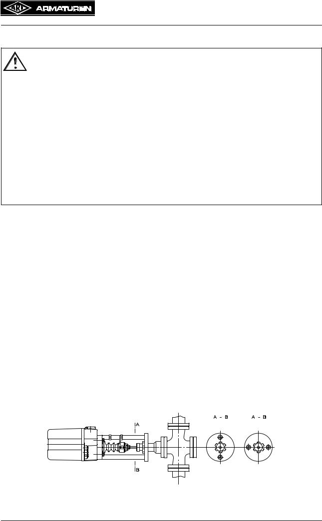
-Thrust actuator mountable in any position except in downward suspended position.
If installed with a horizontal connecting rod, the thrust actuator must be mounted so both yoke legs or columns are on top of one another in the vertical plane (see Fig. 4 ).
Correct Incorrect
Fig. 4
0040501004 5010 |
Page 15 |
Loading...