


Operating and installation instructions
Electronic position indicator RI21
Contents
1.0 General information on operating
instructions ..................................................2-2
2.0 Notes on possible dangers.........................2-2
2.1 Significance of Symbols .....................................2-2
2.2 Explanatory notes on safety information ..............2-2
3.0 Storage and transport.................................2-2
4.0 Description...................................................2-3
4.1 Scope of application.............................................2-3
4.2 Operating principle ...............................................2-3
4.3 Technical data ......................................................2-4
4.4 Dimensions ..........................................................2-4
5.0 Installation ...................................................2-5
5.1 General notes on installation................................2-5
5.2 Installation in control cabinet................................2-5
5.3 Installation in ARI-PREMIO actuator....................2-6
5.4 Installation in CS25 to CS27 actuator ..................2-7
5.5 Electrical connection ............................................2-8
5.5.1 Circuit diagram...............................................2-8
5.5.2 Terminal assignments ..................................2-9
5.5.3 Connection Conditions...................................2-9
5.6 Connection in Control Cabinet .............................2-9
5.7 Connection in ARI-PREMIO (circuit diagram)....2-10
5.7.1 ARI-PREMIO 2,2 - 5 kN ...............................2-10
5.7.2 ARI-PREMIO 12 - 15 kN without integrated
reversing contactor .......................................2-11
5.7.3 ARI-PREMIO 12 - 15 kN with integrated
reversing contactor....................................... 2-12
5.8 Connection in ARI-PREMIO (description) ......... 2-13
5.9 Connection in CS25 to CS27 actuator
(circuit diagram)................................................. 2-14
5.10 Connection in CS25 to CS27 actuator
(description) ..................................................... 2-15
6.0 Starting up ............................................... 2-16
6.1 Factory setting................................................... 2-17
6.2 Setting of potentiometer .................................... 2-17
6.3 Type of control signal ........................................ 2-18
6.4 Zero point setting ............................................. 2-19
6.5 Slope span setting ............................................ 2-20
7.0 Care and maintenance.............................. 2-20
8.0 Troubleshooting ........................................ 2-21
9.0 Troubleshooting table .............................. 2-21
10.0 Dismantling of the position indicator .. 2-22
11.0 Warranty / Guarantee .............................. 2-22
12.0 EU declaration of conformity................. 2-23
Rev. 0040602000 1014

Operating and installation instructions
Electronic position indicator RI21
1.0 General information on operating instructions
These operating instructions provide information on mounting and maintaining the fittings.
Please contact the supplier or the manufacturer in case of problems which cannot be
solved by reference to the operating instructions.
They are binding on the transport, storage, installation, start-up, operation, maintenance
and repair.
The notes and warnings must be observed and adhered to.
- Handling and all work must be carried out by expert personnel or all activities must be
supervised and checked.
It is the owner’s responsibility to define areas of responsibility and competence and to
monitor the personnel.
- In addition, current regional safety requirement
taking the fittings out of service as well as when maintaining and repairing them.
The manufacturer reserves the right to introduce technical modifications at any time.
These Operating Instructions comply with the requirements of EU Directives.
s must be applied and observed when
2.0 Notes on possible dangers
2.1 Significance of Symbols
ATTENTION !
. . .
ATTENTION !
. . .
Warning of general danger.
Warning of dangerous voltage.
2.2 Explanatory notes on safety information
In these Operating and Installation Instructions dangers, risks and items of safety
information are highlighted to attract special attention.
Information marked with the above symbol and “ATTE NT ION ! ” describe practices, a
failure to comply with which can result in serious injury or danger of death for users or third
parties or in material damage to the system or the environment. It is vital to comply with
these practices and to monitor compliance.
All other information not specifically emphasised such as transport, inst
and maintenance instructions as well as technical data (in the operating instructions,
product documentation and on the device itself) must also be complied with to the fullest
extent in order to avoid faults which in turn can cause serious injury to persons or damage
to property.
allation, operating
3.0 Storage and transport
- At -20° to +70°C dry, free from dirt.
- Do not unpack electronics p
- Protect against external force (imp
- Do not soil or damage type identification plate and wiring diagram on the controller.
Page 2-2 Rev. 0040602000 1014
rior to installation.
act, vibration etc.).

Operating and installation instructions
Electronic position indicator RI21
4.0 Description
4.1 Scope of application
The electronic position indicator RI21 is used for converting electrical resistances of up to
1000 to electrical signals.
The electronic position indicator RI21 is suitable for installation in switch cabinets as well as
in the actuator ARI-Premio or in actuators ARI CS25 through CS27.
Electronic position indicators installed in an actuator serve to indicate exact positioning.
The ambient conditions have to be conform to the actual electromagnetic compatibility
directives. Additional the compatibility to this directives has to be maintained in case of
expansion or other changings of the ambient conditions.
4.2 Operating principle
The Ready Status on the electronic position indicator is indicated by a yellow LED.
The positioning signal is selected by means of the slide switch SY.
Matching of the resistance input and positioning signal output is ef
potentiometers.
The positioning signal outputs Yu and Yi are dependent on set resistance value of the
connected potentiometer.
The control section is (electrically) DC-decoupled from the mains input.
fected via trimming
ATTENTION !
For use on a three-wire system, the ground input may only be connected up to
the N contact of the mains input on the 24V AC version.
The new contact is referred to as zero potential (0V)
Rev. 0040602000 1014 Page 2-3

Operating and installation instructions
Electronic position indicator RI21
4.3 Technical data
Operating Voltage U
Operating current I
Output positioning signal Y
Output positioning signal Y
Potentiometer input R
Type of enclosure IP40 (clamps IP20)
Ambient temperature -20....+70 °C
24V 50-60Hz
B
-20% +10%
150 mA 40 mA 20 mA
B
0(2) ... 10V DC (working resistance > 1000 )
u
0(4) ... 20mA DC (working resistance < 800 )
i
0....1000 (Tol. +30/-50%)
p
4.4 Dimensions
115V 50-60Hz
-20% +10%
230V 50-60Hz
-20% +10%
Fig. 1
Page 2-4 Rev. 0040602000 1014

5.0 Installation
ATTENTION !
Work on electrical systems or equipment must only be carried out by qualified
electricians or by trained individuals under the guidance and supervision of a
qualified electrician in compliance with regional electrical requirements and
regulations.
When connecting electronics the supply line must be disconnected from the
mains (not live) during connection work. Non-compliance may result in death,
serious injury or substantial damage to property.
- The power supply and data provided on the type identification plate must agree.
- Do not touch live parts when carrying out adjustments.
- Take particular caution at volt
- Do not disconnect or connect series isolating terminals with the power on!
- Ground connection between N and is only pe
- Only one actuator is to be connected at any one time.
- Do not overshoot the range of the actuator when carrying out adjustments,
danger of damage.
- Ensure that the motor connected in the actuator switches off in the end
positions based on distance or torque.
Operating and installation instructions
Electronic position indicator RI21
ages above 24 V!
rmitted in the 24 V version.
5.1 General notes on installation
The electronic position indicator RI21 can be installed in a switch cabinet or in the actuator
ARI-PREMIO as well as in actuators CS25 through CS27.
Retrofitting of the electronic position indicator RI21 is possible on the ARI-PREMIO
actuator.
On actuators CS25 through CS27 retrofitting of the electronic position indicator RI21 is
conditional.
Please address all technical queries direct to ARI-ARMATUREN.
- Regional electrical requirement
lines and making electrical connections.
- The cable cross-section must always correspond to the relevant input current and the
cable length.
- The rated mains voltage and mains frequency must agree with the data on the type
identification plate.
Mains power fuse protection, installation side: 6 A max.
s and regulations must be observed when laying electricity
5.2 Installation in control cabinet
- The controller is mounted on a profile rail in the control cabinet in accordance with DIN
46277.
- The mounting grid for control panel installation is L 58 mm x W 35 mm.
Installation parts:
- 1 electronic position indicator RI21
Rev. 0040602000 1014 Page 2-5

Operating and installation instructions
B
C
A
Electronic position indicator RI21
5.3 Installation in ARI-PREMIO actuator
Refer to figures below for installation in ARI-PREMIO actuator.
Fig. 2: Installation RI21 / ES11 ARI-PREMIO 2,2 - 15 kN
Installation procedure:
Carefully remove cover.
A Fit mounting bracket (50.80) at point on gear cover provided for this purpose.
Secure with two socket head cap screws (50.81) DIN EN ISO 4762 - M4x8.
B/C Secure the electronic position indicator RI21 (50.78/79) with two socket head
cap screws (50.82) DIN EN ISO 4762 - M4x12 on mounting bracket (50.80).
ATTERNTION !
For potentiometer installation, refer to ARI-PREMIO operating instructions
Installation parts:
- 1 electronic position indicator RI21
- 1 Mounting bracket ES11/RI21
- 2 Socket head cap screws DIN EN ISO 4762 - M4x8
- 2 Socket head cap screws DIN EN ISO 4762 - M4x12
- 1 1000 Ohm potentiometer
- 1 Potentiometer cable
- 2 PT screws KB 22x8 WN1412-Zi
- 1 Sliding block
- 1 Torsion spring
- 1 Washer
- 1 Spur gear 16 teeth for 20 mm stroke, or
24 teeth for 30 mm stroke, or
39 teeth for 50 mm stroke, or
49 teeth for 65 mm stroke, or
59 teeth for 80 mm stroke
Page 2-6 Rev. 0040602000 1014

Operating and installation instructions
Electronic position indicator RI21
5.4 Installation in CS25 to CS27 actuator
Refer to figure below for installation in CS25 to CS27 actuator.
Fig. 3
Installation procedure:
- Carefully remove cover.
- Loosen capacitor, for this purpose, release corresponding cable ties.
- Secure capacitor plate with screw DIN EN ISO 4762 - M8x10 on to gearbox cover.
- Install capacitor on capacitor plate
- Secure mounting bracket on gearbox cover with two self-tapping screws DIN7500 - M4x8.
- Secure RI21 to mounting bracket with two socket head cap screws DIN EN ISO 4762 M4x12.
- Tie together newly installed cables with cable ties.
- Remove old circuit diagrams from cover and affix new circuit diagram in cover.
ATTENTION !
For potentiometer installation, refer to operating instructions for CS actuators.
Mounting parts:
- 1 electronic position indicator RI21
- 1 Mounting bracket ES11/RI21
- 2 Socket head cap screws DIN EN ISO 4762 - M4x12
- 1 Socket head cap screws DIN EN ISO 4762 - M8x10
- 1 Capacitor plate
- 2 Self-tapping screws DIN 7500 - M4x8
- 1 1000 Ohm potentiometer, soldered
- 2 Lock rings for potentiometer
- 1 Pinion for potentiometer
- 1 CS electronic position indicator cable
- 1 Circuit diagram RI21 + CS25
- 2 Cable ties
Rev. 0040602000 1014 Page 2-7

5.5 Electrical connection
5.5.1 Circuit diagram
Operating and installation instructions
Electronic position indicator RI21
Fig. 4
Page 2-8 Rev. 0040602000 1014

Operating and installation instructions
Electronic position indicator RI21
5.5.2 Terminal assignments
Power input
N Terminal - power input Neutral conductor
............ ...................
L Terminal - power input Phase
............ ...................
Actuating signal output
Y
............ .................
i
Y
........... .................
u
Terminal - ground, GND.................0 V
............
Terminal - output signal +...20 mA DC
Terminal - output signal +...10 V DC
Potentiometer input
R
..........
P
R
...........
a
...............
Potentiometer ...............................0...1000
Terminal - potentiometer input
dashed line (yellow wire)
must‘nt be connected because Ra is internally wired with
R
b
R
..........
b
R
........... .......
c
Terminal - potentiometer input ...... (grey wire)
Terminal - potentiometer input (red wire)
5.5.3 Connection Conditions
All electrical terminals are connected to the electronic position
indicator RI21 by means of series isolating terminals. The
suitable conductor cross-sections for connecting the terminals
are 0.2 to 2.5 mm2. To achieve optimal electromagnetic
compatibility it is recommended to use shielded cables for
connecting potentiometers or standardized active current or
voltage signals.
Please contact the manufacturer direct for technical
information.
Fig. 5
ATTENTION !
To facilitate use in 3-conductor technology, the ground output may be
connected to the N contact of the power input only in the 24 V AC version.
The new contact is then referred to as zero potential (0V)
Fuse protection of mains power supply on system side: 6 A max.
5.6 Connection in Control Cabinet
Power input for connection in control cabinet
The voltage supply is connected to terminals N and L in accordance with the type
identification plate.
Actuating signal output for connection in control cabinet
The actuating signal output ...20 mA is connected to terminals Yi and .
The actuating signal output ...10 V is connected to terminals Yu and .
ATTENTION !
Only one actuating signal output may be connected at any one time.
Potentiometer input for connection in control cabinet
A 1000 Ohm potentiometer is connected to terminals Ra, Rb, Rc.
The wiper is connected to Rb.
With the valve closed, there are 0 Ohms between R
Rev. 0040602000 1014 Page 2-9
and Rc.
b

Operating and installation instructions
accessories
closed
open
open
open
open
open
Straightthrough valve
3-way valve
with diverting plug
3-way valve
with mixing plug
Electronic position indicator RI21
5.7 Connection in ARI-PREMIO (circuit diagram)
5.7.1
ARI-PREMIO 2,2 - 5 kN
Fig. 6
Page 2-10 Rev. 0040602000 1014

Operating and installation instructions
accessoriesStandard
closed
open
open
open
open
open
Straightthrough valve
3-way valve
with diverting plug
3-way valve
with mixing plug
Electronic position indicator RI21
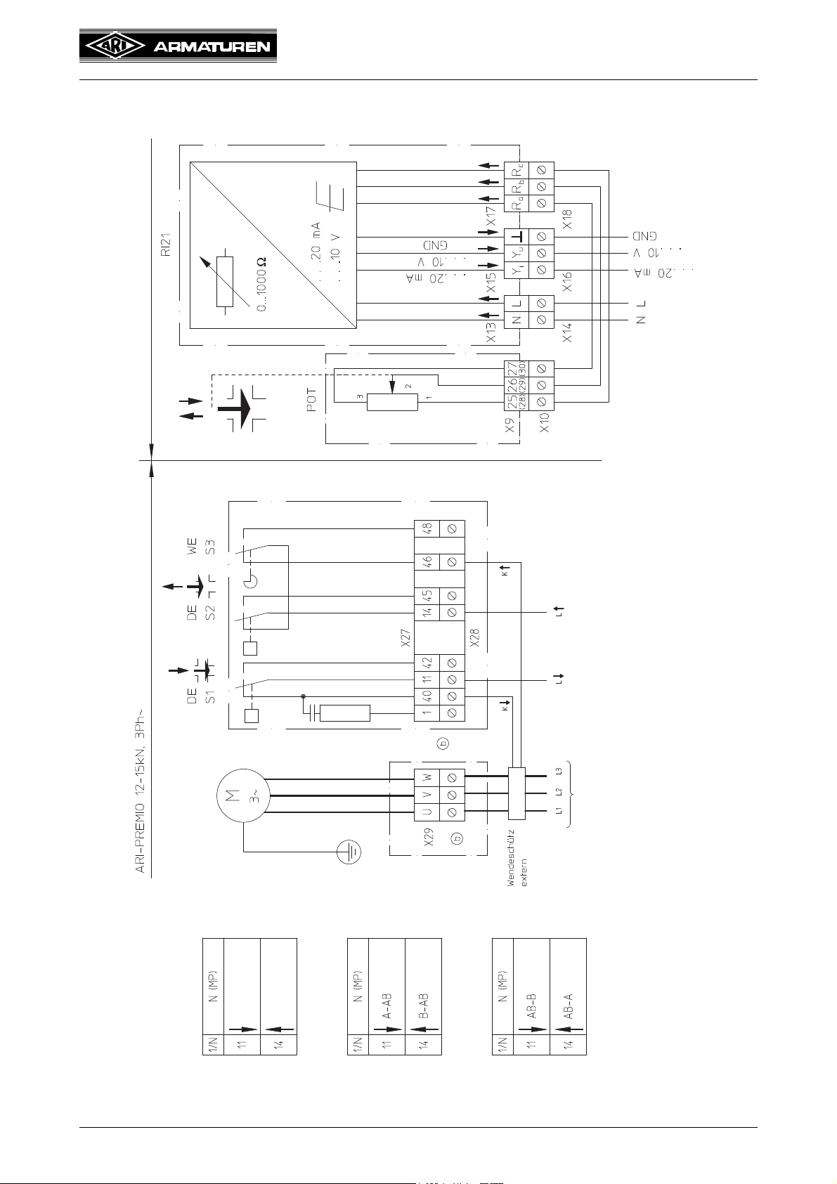
5.7.2 ARI-PREMIO 12 - 15 kN without integrated reversing contactor
Rev. 0040602000 1014 Page 2-11
Fig. 7
Operating and installation instructions
closed
open
open
open
open
open
Straightway valve
3-way valve
with diverting plug
3-way valve
with mixing plug
External reversing contactor:
L1, L2, L3 - actuator spindle drives in
L3, L2, L1 - actuator spindle drives out
In all external reversing circuits the torque switches S1 and S2 have to be
used to switch off the actuator motor.
accessories
Standard
Electronic position indicator RI21
5.7.3 ARI-PREMIO 12 - 15 kN with integrated reversing contactor
Fig. 8
Page 2-12 Rev. 0040602000 1014

Operating and installation instructions
Electronic position indicator RI21
5.8 Connection in ARI-PREMIO (description)
Also refer to ARI-PREMIO operating instructions
Power input for connection in ARI-PREMIO
The voltage supply is connected to terminals N and L in accordance with type identification
plate.
Actuating signal output for connection in ARI-PREMIO
The actuating signal output ...20 mA is connected to terminals Yi and .
The actuating signal output ...10 V is connected to terminals Yu and .
ATTENTION !
Only one actuating signal output may be connected at any one time.
Potentiometer input for connection in ARI-PREMIO
ATTENTION !
When installing the potentiometer, observe the operating instructions for the
electrical linear actuator ARI-PREMIO.
Plug connector Ra, Rb, Rc from potentiometer cable into electronic position indicator RI21
and connector 25, 26, 27 into ARI-PREMIO pin block.
Rev. 0040602000 1014 Page 2-13

Operating and installation instructions
standard
accessories (plus value)
Electronic position indicator RI21
5.9 Connection in CS25 to CS27 actuator (circuit diagram)
Fig. 9
Page 2-14 Rev. 0040602000 1014

Operating and installation instructions
Electronic position indicator RI21
5.10 Connection in CS25 to CS27 actuator (description)
Also refer to CS25-27 operating instructions
Power input for connection in CS actuator
The voltage supply is connected to terminals N and L in accordance with the type
identification plate.
Actuating signal output for connection in CS actuator
The actuating signal output ...20 mA is connected to terminals Yi and .
The actuating signal output ...10 V is connected to terminals Yu and .
ATTENTION !
Only one actuating signal output may be connected at any one time.
Potentiometer in CS actuator
ATTENTION !
When installing the potentiometer, refer to operating instructions for electrical
linear actuator CS25.
Plug connector Ra, Rb, Rc from potentiometer cable into the
electronic position indicator RI21.
Unscrew connector 25, 26, 27 and connect cable in actuator.
RA ............... Terminal - potentiometer input (yellow cable) .........to terminal 27 (30)
RB ............... Terminal - potentiometer input (grey cable).............to terminal 26 (29)
RC ...............Terminal - potentiometer input (red cable) ..............to terminal 25 (28)
Rev. 0040602000 1014 Page 2-15

Operating and installation instructions
Electronic position indicator RI21
6.0 Starting up
ATTENTION !
- The thrust actuator should only be operated for short periods without a hood
when carrying out essential adjustments to potentiometers, directional switches
and electrical options. During such activities the thrust actuator has hazardous
live, bare parts as well as moving and rotating parts.
- Careless or unprofessional adjustments can lead to death, serious physical
injury or substantial damage to property.
- Operating the thrust actuator without a hood is prohibited for any purpose other
than that described above.
- Electronics must be moisture-free.
Before starting up a new system or restarting a system following repair or modification
check:
- that regional safety instructions have been complied with as a matter of principle
- that the data on power supply
with the technical data on the electronics.
- that all work has been properly completed!
, actuating signal and ambient temperature are consistent
ATTENTION !
- The adjustment to the RI21 can only be performed when the actuator is
mounted onto a valve.
- Observe the order of the settings:
1. Potentiometer (refer to 6.2)
2. Type of control signal (refer to 6.3)
3. Zero point (refer to 6.4)
4. Slope span (refer to 6.5)
- In case of subsequent changes to a setting, the following settings must be
readjusted!
- Example:
If the type of control signal (point 2) is changed, the zero point (point 3) and the
slope span (point 4) must be readjusted.
The hood must be installed after completing the adjustments!
Page 2-16 Rev. 0040602000 1014

Operating and installation instructions
Electronic position indicator RI21
6.1 Factory setting
Upon delivery of the RI21 with a cpl. control device (valve and actuator), the potentiometer
and the RI21 are adjusted by factory to it’s valve travel. The factory setting is indicated with
a waterproof marker or a sticker on the nameplate.
If the order was given without indication of a special control signal, the default is 4-20mA.
4mA for a closed valve.
6.2 Setting of potentiometer
a) To adjust the potentiometer in the actuator, the operating instructions of the
corresponding actuator have to be observed.
b) Switch-off mains voltage and secure against unintentional reconnection.
c) Turn the potentiometer to 0 Ohm position.
- At PREMIO-actuator turn the potentiometer spindle counter-clockwise until it stops
(0
Ohm position).
- For inspection, the resistance of the potentiometer must be measured with an
ohmmeter.
For resistance measurement disconnect the potentiometer from the RI21 position
indicator.
First measurement contact ................RB - grey cable...... - PREMIO terminal 26 (29)
Second measurement contact ...........RC - red cable........ - PREMIO terminal 25 (28)
With completely extended actuator spindle, it must be approx. 0 Ohm between the first
and second measuring contact.
d) Turn thrust actuator with manual handwheel into cpl. retracted position and read the
corresponding resistance value at the Ohmmeter.
- With cpl. retracted actuator stem, 750th .. 1100 Ohm must lie between the first and
second measuring contact.
e) Connect the potentiometer with the RI21 positioner again
f) Connect potentiometer acc. to Fig. 11 : Effective direction (only RI21!)
- For the effective direction INV (refer to Fig. 11), the cables RA and RC have to be
changed at terminal X16:
- red cable to terminal RA
- yellow cable to terminal RC
- For the effective direction NORM (refer to Fig. 11), the cables RA and RC at terminal
X16 have to be connected as following:
- yellow cable to terminal RA
- red cable to terminal RC
- Check and correct if necessary.
Rev. 0040602000 1014 Page 2-17

Switch Type of control
signal
clamp connection at:
Y
U
Voltage signal
max. 10 V DC
for e.g. 0-10V
YU und GND
Y
I
Current signal
max. 20mA DC
for e.g. 4-20mA
YI und GND
NORM:
INV:
Example: Control signal
max. 10V 20mA
min. 0V 4mA
Example: Control signal
min. 0V 4mA
max. 10V 20mA
Control signal
NORM INV
max. min.
min. max.
Operating and installation instructions
Electronic position indicator RI21
6.3 Type of control signal
The selection of the required control signal, is done by
switch SY.
Fig. 10: Effective direction
Fig. 11
: Effective direction
Page 2-18 Rev. 0040602000 1014

Operating and installation instructions
Electronic position indicator RI21
6.4 Zero point setting
- Observe the order of the settings:
1. Potentiometer (refer to 6.2)
2. Type of control signal (refer to 6.3)
3. Zero point (refer to 6.4)
4. Slope span (refer to 6.5)
- In case of subsequent changes to a setting, the following settings must be
readjusted!
a) The voltage supply must be disconnected before carrying out any setting work.
b) Turn the valve stem with the handwheel for the min. control signal in the desired position,
e.g. 4mA or 0V, (according to the switch position SW and as shown in Fig. 11 : Effective
direction). Typically this will be the closed valve.
c) Set the input signal to the minimum required value, e.g. 4 mA or 0 V.
d) Disconnect the line separating terminal X2, X25 or X28 to the motor and let it be
separated.
e) Connect instrument corresponding to the set control signal type to terminal X16
- Yu: voltmeter at terminal Yu and GND
- Yi: amperemeter at terminal Yi and GND
e) Connect voltage at L and N from the 2-pin series isolating terminal, the yellow LED must
be lit.
f) Adjust the zero adjustment screw N until the minimum desired control signal value on the
instrument is shown (after 25 rotations, the slip clutch sets).
- Increase value: turn clockwise,
- Decrease value: turn anti-clockwise.
E.g.:
- Current output ............minimal value .........Yi = 0 mA or 4 mA
- Voltage output..................minimal value ............Yu = 0V or 2V
Rev. 0040602000 1014 Page 2-19

Operating and installation instructions
Electronic position indicator RI21
6.5 Slope span setting
ATTENTION !
- Observe the order of the settings:
1. Potentiometer (refer to 6.2)
2. Type of control signal (refer to 6.3)
3. Zero point (refer to 6.4)
4. Slope span (refer to 6.5)
- In case of subsequent changes to a setting, the following settings must be
readjusted!
a) Turn the valve stem with the handwheel for the max. control signal in the desired
position, e.g. 20mA or 10V (according to the switch position SW and as shown in Fig. 11
: Effective direction). Typically this will be the opened valve.
b) Connect the instrument corresponding to the set control signal type to terminal X16
(if it was disconnected at item 6.4).
- Yu: voltmeter at terminal Yu and GND
- Yi: amperemeter at terminal Yi and GND
c) Adjust the slope span screw S until the maximum desired control signal value on the
instrument is shown (af
- Increase value: turn clockwise,
- Decrease value: turn anti-clockwise.
E.g.:
- Current output ................ m
- Voltage output ..................... maximum value ............Yu = 10V
d) Switch off the power supply to the RI21, and reconnect the terminal X25 or X28 to the
motor.
e) Disconnect measuring instrument
f) After the feedback signal is connected corresponding to the position of the switch SY at
terminal 16 and the switching power supply is also turned on, the position indicator RI21
is ready for operation.
ter 25 rotations, the slip clutch sets).
aximum value .........Yi = 20 mA
7.0 Care and maintenance
The electronic position indicator RI21 requires little maintenance so that specific
maintenance tasks are not specified at set intervals.
Dirt which may build up on the out
indicator RI21 corresponding to operating conditions.
side should be cleaned from the electronic position
ATTENTION !
Before cleaning electronics the supply line must be disconnected from the mains
(not live). It must be impossible to switch the power on unintentionally while the
mains are disconnected in this way.
Failure to comply may result in death, serious injury or substantial damage to
property.
The electronic position indicator RI21 must not be cleaned with watery liquids or with
solvents or detergents which are aggressive, harmful or highly flammable.
Before cleaning, the detergent should preferably be applied to a cleaning cloth. Liquids
must not penetrate into the inside of the electronic position indicator.
Page 2-20 Rev. 0040602000 1014

Operating and installation instructions
Electronic position indicator RI21
8.0 Troubleshooting
In the event of malfunction or faulty operating performance check that the installation and
adjustment work has been carried out and completed in accordance with these Operating
Instructions.
ATTENTION !
-
It is essential that the safety regulations are observed when identifying faults.
If malfunctions cannot be eliminate with the help of the following table
“9.0 troubleshooting table”, the supplier or manufacturer should be consulted.
9.0 Troubleshooting table
ATTENTION !
- read point 10.0 and 11.0 prior to dismantling and repair work!
- read point 6.0 before restarting the plant !
Faults Possible causes Corrective measures
Yellow LED is not lit - Mains failure - Check power supply
- Incorrect operating voltage - Connect operating voltage in
accordance w
plate
- electronic position indicator burnt
out
- Check whether mains voltage
rees with the voltage specified
ag
on type identification plate.
Replace electronic position indicator.
ith type identification
electronic position indicator cannot be adjusted
Output positioning signal in-
capable of being set over the
tire setting distance
en
- Connection terminal not connected
rrectly or cable has no contact in
co
connection terminal
- Potentiometer not connected cor-
rectly
- Potentiometer has incorrec
rating
- Potentiometer connected to incor-
rect terminal
- No signal present at output - Perform settings as under 6.0
- Actuating signal connected to incor-
rect terminal
- Adjusting screws N (zer
S (slope) are out of range
- Spur gear transmission ratio at
poten
tiometer incorrect
- Wrong potentiometer - Use 1000 ohm potentiometer
- Adjusting screws N (zer
S (slope) are out of range
t value
o point) and
o point) and
- Firmly plug in connection terminal
and check connection cable
- Check connections
- Replace potentiometer by
1000 po
- Correct connection in accordance
wit
h circuit diagram
through 6.5
- Correct connection in accordance
wit
h circuit diagram
- Carry out settings as described
under 6.0 to 6.5
- Adapt spur gear transmission ratio
to control range
- Carry out settings as described
under 6.0 to 6.5
tentiometer
Rev. 0040602000 1014 Page 2-21

Operating and installation instructions
Electronic position indicator RI21
10.0 Dismantling of the position indicator
ATTENTION !
- Before dismantling the electronics the supply line must be disconnected from
the mains (not live). It must be impossible to switch the power on unintentionally
while the mains are disconnected in this way.
- The actuating signal must be switched off.
11.0 Warranty / Guarantee
The extent and period of warranty cover are specified in the "Standard Terms and
Conditions of Albert Richter GmbH & Co. KG“ valid at the time of delivery or, by way of
departure, in the contract of sale itself.
We guarantee freedom of faults in compliance with state-of-the-art technology and the
confirmed application.
No warranty claims can be made for any damage caused as the result of incorrect handling
or disregard of operating and installation instructions, dat
asheets and relavant regulations.
This warranty also does not cover any damage which occurs during operation under
conditions deviating from those laid down by specifications or other agreement
Justified complaints will be eliminated by repair carried out by us or by a specialist
appointed by us.
No claims will be accepted beyond the scope of this warranty. The right to replacement
delivery is excluded.
The warranty shall not cover maintenance work, installation of external parts, design
modifications or natural wear.
Any damage incurred during transport should not be reported to us but rather to the
competent cargo-handling depot, the railway company or carrier company immediately or
else claims for replacements from these companies will be invalidated.
s.
Technology for the Future.
GERMAN QUALITY VALVES
ARI-Armaturen Albert Richter GmbH & Co. KG, D-33756 Schloß Holte-Stukenbrock
Telephone (+49 5207) 994-0 Telefax (+49 5207) 994-158 or 159
Internet: http://www.ari-armaturen.com E-mail: info.vertrieb@ari-armaturen.com
Page 2-22 Rev. 0040602000 1014

Operating and installation instructions
........................................................
(Brechmann, managing director)
12.0 EU declaration of conformity
ARI-Armaturen Albert Richter GmbH & Co. KG,
Mergelheide 56-60, D-33756 Schloß Holte-Stukenbrock
EU declaration of conformity
as defined by
EC-Directive about electromagnetic compatibility 2004/108/EC and
EC-Low voltage directive 2006/95/EC and
EU-Directive 2011/65/EU on the restriction of the use
of hazardous substances in electrical and electronic equipment
Herewith we declare, that the supplied model of
Electronic position indicator RI21
Electronic Positioner ES 11 (24V
Electronic Position Indicator RI 21 (24V
in the delivered version complies with the following regulations:
- EC-Directive about electromagnetic compatibility 2004/108/EC
Applied harmonized standards:
DIN EN 61000-6-1/3; DIN EN 61000-6-2/4
- EC-Low voltage directive 2006/95/EC
Applied harmonized standards:
DIN EN 60730-1; DIN EN 60730-2-14; EN 60204-1; EN 60335-1
- EU-Directive on the restriction of the use of certain hazatdous substances in electrical and
electronic equipment 2011/65/EU (RoHS II)
, 115V, 230V) and
, 115V, 230V)
Schloß Holte-Stukenbrock, 04.03.2014
Page 2-23 Rev. 0040602000 1014
 Loading...