

Page 1
22/06/06
Page 1 of 9
3782946
If you have any queries regarding the installation of this product please contact the distributor from whom it was purchased, or alternatively the ARB office in your state.
Head Office – ARB Corporation Ltd VIC: 42-44 Garden Street, Kilsyth, Victoria, 3137 Tel: (03) 9761 6622 Fax: (03) 9761 6807
WA: (08) 9244 3553 NSW: (02) 9821 3633 ACT: (02) 6280 7475 SA: (08) 8244 5001 QLD: (07) 3872 3872 NT: (08) 8947 2262 TAS: (03) 6331 4190
ARB WINCH/NON WINCH BUMPER TO SUIT DODGE RAM PICKUPS
1998 TO 2002
PRODUCT No. 3952010
WARNING
FOR VEHICLES EQUIPPED WITH SRS AIRBAG
WHEN INSTALLED IN ACCORDANCE WITH THESE INSTRUCTIONS, THE FRONT
PROTECTION BAR DOES NOT AFFECT OPERATION OF THE SRS AIRBAG.
TAKE NOTE OF THE FOLLOWING:
• THIS PRODUCT MUST BE INSTALLED EXACTLY AS PER THESE INSTRUCTIONS USING
ONLY THE HARDWARE SUPPLIED.
• IN THE EVENT OF DAMAGE TO ANY BULL BAR COMPONENT, CONTACT YOUR
NEAREST AUTHORISED ARB STOCKIST. REPAIRS OR MODIFICATIONS TO THE
IMPACT ABSORPTION SYSTEM MUST NOT BE ATTEMPED.
• DO NOT USE THIS PRODUCT FOR ANY VEHICLE MAKE OR MODEL, OTHER THAN
THOSE SPECIFIED BY ARB.
• DO NOT REMOVE LABELS FROM THIS BULL BAR.
• THIS PRODUCT OR ITS FIXING MUST NOT BE MODIFIED IN ANY WAY.
FITTING KIT No’s: - 6171447, 6171449, 6171435
Note : If fitting optional fog lights, fitting kit no. 9381FCK is required.
Tools Required
10mm, 18mm, 19mm, 21mm Spanners and Sockets. Phillips head screwdriver, 10mm drill
bit and drill.
IMPORTANT
• This winch bumper is suitable only for Warn 15,000lb winch only.
Page 2

22/06/06
Page 2 of 9
3782946
USE
PART No
QTY
DESCRIPTION
BUFFER FITTMENT
6151128
19
NUT FLANGE M6
3162173 1 BUFFER LOWER
3162153 1 BUFFER LHS
3162154 1 BUFFER RHS
CHROME TUBE FITTMENT
6151255 2 BOLT M12 X 40mm
4581049 2 WASHER FLAT M12
4581050 2 WASHER SPRING M12
6131193 1 CHROME TUBE
MOUNT BRACKETS TO VEHICLE
3756278L
1
BRACKET BAR MOUNT LHS
3756278R
1
BRACKET BAR MOUNT RHS
6151232
12
BOLT M10 X 30mm
4581048
12
WASHER M10 SPRING
4581040
16
WASHER M10 FLAT
3193696L 1 TOW HOOK LHS
3193696R 1 TOW HOOK RHS
CONTROL BOX FITTMENT
3756280 1 CONTROL BOX BRACKET
6151022 2 BOLT M8 X 25MM
180302
8
CABLE TIE
4581044 2 WASHER M8 FLAT
4581046 2 WASHER M8 SPRING
WINCH
4581044 4 WASHER 3/8”
BLB850 2 BATTERY LEAD BLACK
BLR850 1 BATTERY LEAD RED
NUMBER PLATE FITTMENT
6151017 2 BOLT M6 X 16mm
6151128 2 NUT FLANGE M6
6781408 1 TAPE DOUBLE SIDED
AIR DEFLECTOR FITTMENT
6151132 7 NUT M8 FLANGE
6151022 7 BOLT M8 X 25mm
4581044 7 WASHER M8 FLAT
6522010 1 AIR DEFLECTOR PANEL
WINCH COVER FITTMENT
6151128 2 NUT FLANGE M6
6151256
2
SCREW M6 S/STEEL BUTTON HEAD
6191001
1
WINCH COVER EXTRUSION
6522009 1 WINCH COVER
6151046 2 WASHER M6
BAR TO MOUNT ASSEMBLY
6151255 4 BOLT M12 X 40mm
4581050 4 WASHER SPRING M12
4581007
4
WASHER FLAT M12 LARGE
4581048 4 WASHER SPRING M10
6151026
4
NUT M10
6151232 4 BOLT M10 X 25mm
4581040 8 WASHER FLAT M10
LIGHT SURROUNDS TO BAR
3162166 1 LIGHT SURROUND LHS
3162167 1 LIGHT SURROUND RHS
CB
3162152 2 PLASTIC PLUG DIA16
Page 3
22/06/06
Page 3 of 9
3782946
ASSEMBLY SEQUENCE FOR WINCH BUMPER.
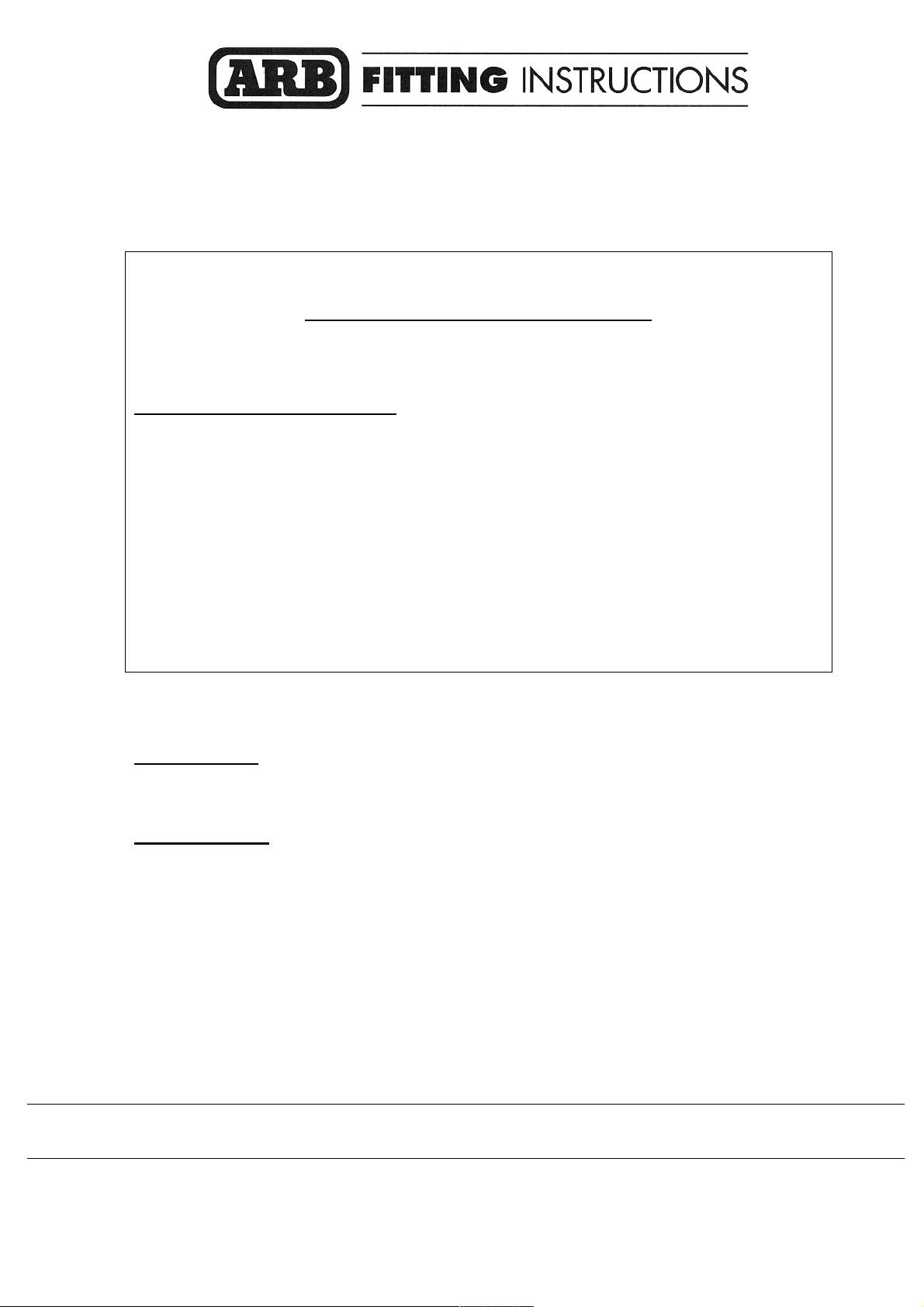
1. Position the lower buffer on the winch bumper and
assemble using the M6 flange nuts. (do not over
tighten)
2. Insert the side buffers through the holes and fix
using the M6 flange nuts. (Do not over tighten)
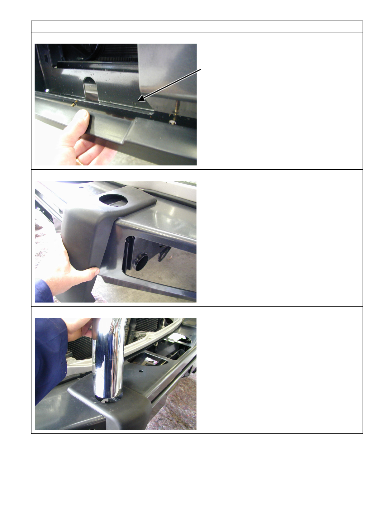
3. Push the top chrome tube through the hole in the
buffer and fasten using the M12 x 40mm bolts,
washers and spring washers.
Page 4

22/06/06
Page 4 of 9
3782946
4. Remove the bumper from the vehicle.
5. Fasten the mount brackets and tow hooks to the
end of the chassis rails using M10 bolts, M10 flat
washers and M10 spring washers.
Tow hooks
6. The mounts need to be pin bolted to the vehicle
chassis.
Mark out the hole 50mm across to the outside and
15mm forward and drill using a 10mm drill bit. Drill
all the way through the top of the bracket and cross
member. Be careful not to damage the radiator
above the cross member.
Fasten hole using M10 bolts, M10 flat washers and
M10 spring washers.
Page 5

22/06/06
Page 5 of 9
3782946
7. Fasten the top hole using M10 bolts, M10 flat
washers and M10 spring washer.
8. If fitting winch.
The clutch handle must be repositioned so it is in a
convenient location when mounted to bar.
Place the winch on its end and remove all gearbox
bolts.
Gently raise the motor just enough to rotate it.
Viewing from the gearbox end, rotate the gearbox
72deg clockwise.
Do not completely remove the motor and avoid
damaging the gasket.
Refit and tighten all bolts.
NOTE: Take care not to lift the assembly more
than a couple of millimeters while rotating to the
desired position to avoid unmeshing the gears.
9.
If fitting winch.
The three control box leads, which connect to
winch, need to be replaced with the longer leads
supplied in the fitting kit. Replace the leads with
similar colours.
Bolt the control box bracket to the control box, refer
photo.
Thread the cable ties through the slots in the
bracket and tie down the cables to the bracket as
shown in photo.
ORIGINAL POSITION
NEW POSITION
ROTATION
Page 6

22/06/06
Page 6 of 9
3782946
10 If fitting winch.
Mount the control box assembly to the bar and
fasten to the winch mount bracket using M8 bolts,
flat washers and spring washers. Run the cables
through the cutout on the passenger side and
cable tie through the slots on the return.
11.
If fitting winch.
Position the winch inside the bar cradle with the
clutch handle positioned on the drivers side. Cable
spools from the bottom. Bolt in position with the
roller fair lead in place.
Connect the winch control box cables to the winch
motor. Refer to the Warn handbook for additional
information. Connect the long winch + & - cables to
the vehicle after the bar is installed. Refer to the
Warn winch manual for vehicle wiring instructions.
12. If not fitting winch.
Wrap rubber extrusion around winch cover.
Place washers over the winch cover fixing holes
located on the top middle face of the winch
bumper.
Place the winch cover on top of the winch bumper
inline with the mount holes.
Bolt together using the M6 button head stainless
steel screws and M6 nuts.
Page 7

22/06/06
Page 7 of 9
3782946
13. Using two people, three if winch fitted, position the
bar assembly on the vehicle mounts.
14. Bolt the bar to the mounts using M12 bolts, large
flat washers and spring washers. Align bar to the
profile of the guards the guards and tighten all
bolts.
15. The bar must be pin bolted to the mount brackets.
Using a drill and 10mm drill bit, drill through the
upper and lower Ø10mm holes located in the
mount brackets.
Fasten the holes using M10 bolts, flat washers and
spring washers.
Page 8

22/06/06
Page 8 of 9
3782946
16. Bolt the air deflector to the underside of the bar
and chassis cross member using M8 bolts, M8 flat
washers and M8 spring washers.
17. If fitting with winch.
Feed the winch cable through the roller fair lead.
Mount the hook to the end of the cable.
18. Glue the light surrounds to the bar using a silicone
based rubber adhesive. Run the bead along the
cavity on the rear side of the part. Position the
surround to align the inside edge with the buffer
and concentric to the light.
Wipe off any adhesive on the front face of the bar.
Allow adhesive to cure before continuing.
Page 9

22/06/06
Page 9 of 9
3782946
19. There are two Ø16 holes located on the top face of
the bar. If no CB aerials are fitted the holes can be
covered with the plastic plugs provided in the fitting
kit.
Place the ARB logo on the front face of the bar in
the indentation.
20. If fitting fog lights, wire the fog lights as described in the fog light fitting instructions.
The fog lights can be adjusted to desired angles by the adjustment bolts located at the back of the light
insert. When adjustment is finalized, be sure to retighten the fog light bolts.
If fitting with winch.
21. Connect the long winch + & - cables to the vehicle after the bar is installed.
Refer to the Warn winch manual for vehicle wiring instructions.
Ensure that these cables are installed well clear of sharp, hot or moving objects. Secure the winch cables to
the vehicle and winch bumper with the supplied cable ties.
Optional Extras suited for this bar includes a range of IPF driving lights and fog lights (Kit no. 9381FCK).
Contact you’re nearest ARB stockiest for further information.
 Loading...