

Page 1
02/12/04
Page 1 of 12
3782865
ARB WINCH/NONWINCH BUMPER TO SUIT NISSAN PATHFINDER
2/99 ON
PRODUCT No. 3938020
WARNING
FOR VEHICLES EQUIPPED WITH SRS AIRBAG
WHEN INSTALLED IN ACCORDANCE WITH THESE INSTRUCTIONS, THE FRONT
PROTECTION BAR DOES NOT AFFECT OPERATION OF THE SRS AIRBAG.
TAKE NOTE OF THE FOLLOWING:
• THIS PRODUCT MUST BE INSTALLED EXACTLY AS PER THESE
INSTRUCTIONS USING ONLY THE HARDWARE SUPPLIED.
• IN THE EVENT OF DAMAGE TO ANY BULL BAR COMPONENT, CONTACT
YOUR NEAREST AUTHORISED ARB STOCKIST. REPAIRS OR
MODIFICATIONS TO THE IMPACT ABSORPTION SYSTEM MUST NOT BE
ATTEMPED.
• DO NOT USE THIS PRODUCT FOR ANY VEHICLE MAKE OR MODEL,
OTHER THAN THOSE SPECIFIED BY ARB.
• DO NOT REMOVE LABELS FROM THIS BULL BAR.
• THIS PRODUCT OR ITS FIXING MUST NOT BE MODIFIED IN ANY WAY.
Note:
1 If fitting optional fog lights, fitting kit no. 9381FCK is required.
2 This winch bumper is suitable for Warn 8,000lb, 9,000lb & 9,500HS
winch only.
Tools Required
10, 12,13, 14, 18, 19mm Spanners and Sockets. Phillips head screwdriver , Sharp
Knife.
Drill and 6.5mm or ¼” Bit. Black silicone.
Page 2

02/12/04
Page 2 of 12
3782865
FITTING KIT No. 6171387, 6171391, 6171364
USE
PART No
QTY
DESCRIPTION
BUFFER FITTMENT
6151128
17
NUT FLANGE M6
3162158 1 BUFFER LOWER
3162153
1
BUFFER LHS
3162154
1
BUFFER RHS
LIGHT SURROUNDS TO BAR
3162156 1 LIGHT SURROUND LHS
3162157 1 LIGHT SURROUND RHS
CHROME TUBE FITTMENT
6151255 2 BOLT M12 X 40mm
4581049 2 WASHER FLAT M12
4581050 2 WASHER SPRING M12
6131174
1
CHROME TUBE
MOUNT ASSY TO VEHICLE
3751859L
1
BRACKET IMPACT ABSORBER LHS
3751859R
1
BRACKET IMPACT ABSORBER RHS
4581011 2 WASHER FLAT 27x12x4mm
WING BRACE
BAR TO VEHICLE
3756195L
3756195R
1
1
BRACE WING
BRACE WING
6151256
2
BOLT M6 BUTTON HEAD S/STEEL
4581072 2 WASHER M6 x 19mm
6151017 2 BOLT M6 x 16mm HEX HEAD
6151128 4 NUT M6 FLANGE
4581072 2 WASHER 19x7x1.6mm
WINCH
4581044
4
WASHER 3/8”
CONTROL BOX FITMENT
3756220 1 CONTROL BOX BRACKET
6151017 2 BOLT M6 X 16MM
6151128 4 NUT FLANGE M6
WINCH COVER FITTMENT
6151128 2 NUT FLANGE M6
6151256
2
SCREW M6 S/STEEL BUTTON HEAD
6191001 1 WINCH COVER EXTRUSION
6521031
1
WINCH COVER
4581035
2
WASHER M6
RUBBER EXTRUSION FITMENT
6821116
14
SQUARE PLASTIC PLUG
6151176
14
SCREW SELF TAPPING 12mm 8G
6191002
2
EXTRUSION
3193649
2
MOUNT STRIPS
WINCH BUMPER TO MOUNT
ASSEMBLY
6151255 6 BOLT M12 X 40mm
4581050 6 WASHER SPRING M12
4581007 6 WASHER FLAT M12 LARGE
CB
3162152 2 PLASTIC PLUG DIA16
ROLLER FAIRLEAD FITTMENT
4581049 4 WASHER FLAT M12
NUMBER PLATE FITTMENT
6151017 2 BOLT M6 X 16mm
6151128 2 NUT FLANGE M6
6781408 1 TAPE DOUBLE SIDED
WIRING
180302
10
CABLE TIE
Page 3
02/12/04
Page 3 of 12
3782865
ASSEMBLY SEQUENCE FOR WINCH BUMPER.
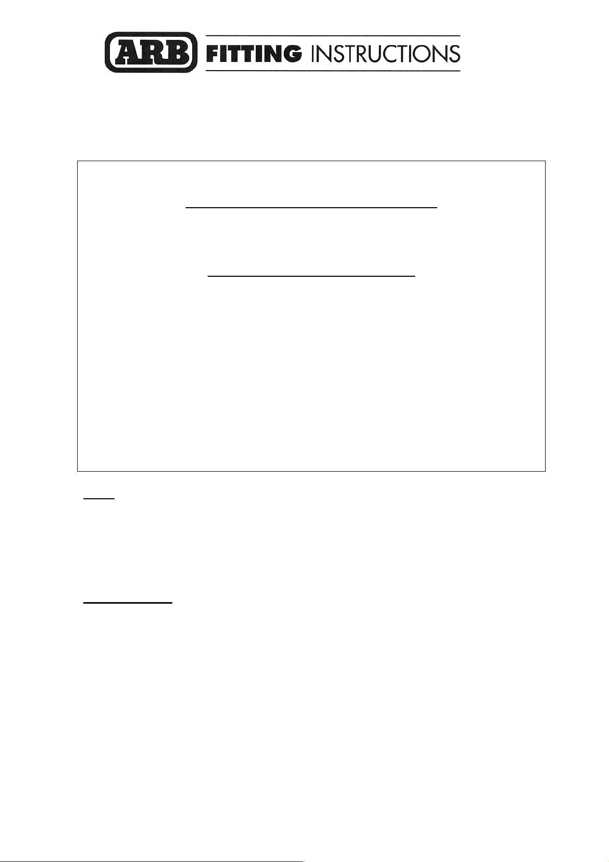
1. 1. Position the lower buffer on the winch
bumper and assemble using the M6 flange
nuts.
2. 1. Insert the side buffers through the holes and
fix using the M6 flange nuts.
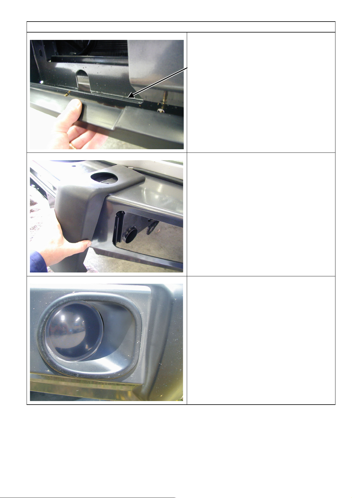
3. 1. Glue the light surrounds to the bar using a
silicone based rubber adhesive. Run the
bead along the cavity on the rear side of the
part. Position the surround to align the inside
edge with the buffer and concentric to the
light.
2. Wipe off any adhesive on the front face of
the bar. Allow adhesive to cure before
continuing.
3. If fitting optional fog lights, do so at this
stage.
Page 4
02/12/04
Page 4 of 12
3782865
ASSEMBLY SEQUENCE FOR WINCH BUMPER.
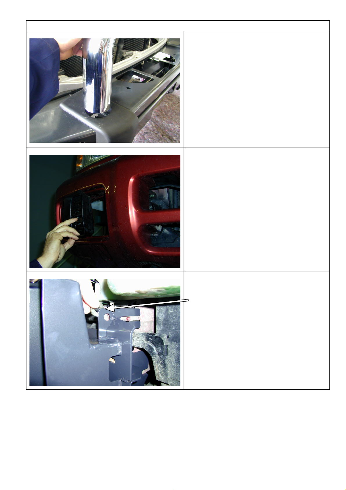
4. 1. Push the top chrome tube through the hole
in the buffer and fasten using the M12 x 40mm
bolts, washers and spring washers.
5. 1. Remove the bumper bar.
1. Remove inner guard trims, left and right.
2. Remove Tow Hooks.
3. Remove Impact Absorbers.
NOTE: Set aside all original mounting hardware
and inner guard trims.
6. 1. Mount the Impact Absorber brackets to each
side of the chassis using original fasteners.
2. Fit spacer washer 27 x 12 x 4mm to top hole
of bracket and fasten.
Page 5

02/12/04
Page 5 of 12
3782865
ASSEMBLY SEQUENCE FOR WINCH BUMPER.
7. 1. Fasten the wing braces to the vehicle using
M6 Hex bolts, washers and flange nuts.
2. On the drivers side undo washer bottle and
carefully cut off retaining hook with a sharp
blade.
3. Pass the wing support brace between the
bottle and the body aligning the holes.
4. Replace the original bolt, clamping the brace
in place.
5. Using a 6.5mm or ¼” drill, drill through
washer bottle brackett using the brace hole
as a guide.
6. Fasten with M6 Hex head bolt and flange nut.
Note: - On passenger side use panel washers
19x7x1.6mm
8. (If fitting the winch.)
1. To place the winch clutch handle in a
convenient location the winch gearbox must
be rotated 2 hole spacings, 72 degrees, in an
anti-clockwise direction when viewed from
the gearbox end. Place the winch on its end
and remove all gearbox bolts. Gently raise
the gearbox just enough to rotate it. Do not
completely remove the gearbox and avoid
damaging the gasket. Refit all bolts and
tighten.
NOTE: Take care not to lift the assembly more
than a couple of millimetres while rotating to the
desired position to avoid unmeshing the gears.
9. 1. To place the winch motor in the correct
location the winch motor must be rotated 90
degrees, in a clockwise direction when
viewed from the motor end. Place the winch
on its end and remove the 2 motor retaining
bolts. Gently raise the motor just enough to
rotate it. Do not completely remove the motor
and avoid damaging the gasket. Refit all bolts
and tighten.
NOTE: Take care not to lift the assembly more
than a couple of millimetres while rotating to the
desired position to avoid unmeshing the gears.
Page 6

02/12/04
Page 6 of 12
3782865
ASSEMBLY SEQUENCE FOR WINCH BUMPER.
10. 1. Bolt the winch and roller fair lead to the bar
using the bolts supplied. The longer bolts are
used for the two bottom holes through the roller
fair lead.
11. 1. If fitting the XP 9.5 winch, remove the cover from
the control box.
For any other winch, go to step 17.
12. 1. Remove the two cap screws, nuts and spacer
washers that hold the four solenoids in place.
Page 7

02/12/04
Page 7 of 12
3782865
ASSEMBLY SEQUENCE FOR WINCH BUMPER.
13. 1. Remove the four solenoids from the base of the
control box using the copper bus bar as an aid and
hold to one side.
14.
Before
1. Remove the two bolts in the base of the control box
and reposition them into the more centralised holes
After
15. 1. Place the 4 solenoids over the 2 metal stands that
are facing upwards. Make sure they line up with the
holes in the base.
Page 8

02/12/04
Page 8 of 12
3782865
ASSEMBLY SEQUENCE FOR WINCH BUMPER.
16. 1. Replace the 2 cap screws, washers and nuts
removed in step 12 above into original holes.
2. Replace the black cover and refit the three cover
screws (DO NOT OVER TIGHTEN)
17.
1. Install the winch and roller fairlead using
bolts, nuts and spring washers supplied by Warn,
and the 4 x 3/8” flat washers supplied in the bolt
kit. Refer to Warn installation instructions for
correct procedure. Adjust winch in slots until the
winch is centralised in the bull bar.
1. Assemble the control box bracket to the
control box using M6 flange nuts.
2. Mount the control box to the bar using M6 X
16 bolts and M6 flange nuts.
NOTE: The gearbox is on the passenger side for
the 8,000lb and 9,000lb. The cable spools from
the bottom for the two winches mentioned.
18. (If not fitting winch)
1. Wrap rubber extrusion around winch cover.
2. Place washers over the winch cover fixing
holes located on the top middle face of the
winch bumper.
3. Place the winch cover on top of the winch
bumper inline with the mount holes.
Bolt together using the M6 button head stainless
steel screws and M6 nuts.
Page 9

02/12/04
Page 9 of 12
3782865
ASSEMBLY SEQUENCE FOR WINCH BUMPER.
19.
With winch
Without winch
(If fitting with winch.)
1. Peel off one side of the double sided tape
and adhere to the top rear side of the number
plate. Note: Clean the adhering surfaces
before applying tape with an alcohol solvent.
2. Peel off the other side of the tape and bolt to
the winch bumper with the M6 X 16mm bolts
and M6 flange nuts through the lower holes
of the number plate.
3. Press firmly to the top of the number plate so
the tape can properly adhere.
(If not fitting with winch.)
1. Bolt the number plate through the top holes
using M6 X 16mm bolts and M6 flange nuts.
If desired the double sided tape can be used
down the sides of the number plate.
20. 1. The rubber extrusion contains a support
section to assist in the moulding. Remove
this section by tearing at one end. Discard
this section.
2. Insert the square plastic plugs into the square
holes on the top face of the wing.
21. 1. Insert the mount strips inside the channel
section of the rubber extrusion. Make sure
the flap section is on the outer side. Allow
generous even amounts of excess at either
end of the strip so that it can be trimmed
later.
Page 10

02/12/04
Page 10 of 12
3782865
ASSEMBLY SEQUENCE FOR WINCH BUMPER.
22.
1. Using a Philips head screw driver or cordless
drill with a Philips head tip fix the extrusions
to the top of the wings using the self taping
screws.
23. 1. Using a sharp knife cut the excess rubber in
line with the inside end of the wing. Only cut
the inside excess, the other end will be cut
when the winch bumper is fitted.
24. 1. With the aid of another person carefully place
the bar on the mounting brackets.
2. Horizontally and vertically align the bar to the
body and fasten using the six M12 x 40mm
bolts, large washers and M12 spring
washers. Tighten all bolts so as the large
washer deforms inside the rectangular
cutout.
Page 11

02/12/04
Page 11 of 12
3782865
ASSEMBLY SEQUENCE FOR WINCH BUMPER.
25. 1. There are two diameter 16 holes located on
the top face of the bar. If no CB aerials are fitted
the holes can be covered with the plastic plugs
provided in the fitting kit.
2. Place the ARB logo on the front face of the
bar in the indentation.
26. (If fitting with winch)
1. Feed the winch cable through the roller fair
lead. Mount the hook to the end of the cable.
27. 1. To replace inner guard trims, reposition on
the vehicle and mark out the edge of the
bullbar wing
2. Using a sharp knife or scissors trim and refit
the guard allowing enough to drill and
position to the bar.
Note: - The trim will sit between the wing brace
and the bullbar wing.
Page 12

02/12/04
Page 12 of 12
3782865
ASSEMBLY SEQUENCE FOR WINCH BUMPER.
28. 1. Trim off excess plastic as shown.
2. With the trim between the brace and the wing
mark, via the hole in the wing, mark with a
felt tip pen or a scriber.
3. Remove the trim and drill using 6.5mm or ¼”
drill bit.
4. Reposition on the vehicle and fasten using
dome head s/steel bolts and flange nuts.
29.
If fitting fog lights, wire the fog lights as described in the fog light fitting instructions
The fog lights can be adjusted to desired angles by the adjustment bolts located at the back of the
light insert. When adjustment is finalised be sure to retighten the fog light bolts.
30. (If fitting with winch)
Connect the winch control box cables to the winch motor. Refer to the Warn handbook for additional
information. Connect the long winch + & - cables to the vehicle after the bar is installed.
Refer to the Warn winch manual for vehicle wiring instructions.
Ensure that these cables are installed well clear of sharp, hot or moving objects. Secure the winch
cables to the vehicle and winch bumper with the supplied cable ties.
 Loading...