


R
INSTALLATION
AND
OPERATING
INSTRUCTIONS
Model: M Series
DIAGONAL CONTACT CONVEYOR TOASTER
Model: AT / BT Series
HORIZONTAL RADIANT CONVEYOR TOASTER
INTENDED FOR OTHER THAN HOUSEHOLD USE
RETAIN THIS MANUAL FOR FUTURE REFERENCE
UNIT MUST BE KEPT CLEAR OF COMBUSTIBLES AT ALL TIMES
WARNING: Improper installation, adjustment, alteration, service or maintenance can
! cause property damage, injury or death. Read the Installation, Operating and ! Maintenance Instructions thoroughly before installing or servicing this equipment.
This equipment has been engineered to provide you with year-round dependable service when used according to the instructions in this manual and standard commercial kitchen practices.
Phone: |
+1 |
(214) |
421-7366 |
P/N 57212 5/12 |
|
||||
Fax: |
+1 |
(214) |
565-0976 |
APW WYOTT |
Toll Free: +1 |
(800) |
527-2100 |
||
Website: www.apwwyott.com |
729 Third Avenue |
|||
E-mail: |
info@apwwyott.com |
Dallas, TX 75226 |
||
1

TABLE OF CONTENTS
GENERAL INFORMATION AND TROUBLESHOOTING |
2 |
M SERIES - DIAGONAL CONTACT CONVEYOR TOASTERS |
3-9 |
Electrical Specifications |
3 |
Installation |
3 |
Location |
6 |
Operating Instructions |
6 |
FieldAdjustments & Cleaning |
7 |
Troubleshooting Guide |
9 |
AT SERIES - HORIZONTAL RADIANT CONVEYOR TOASTERS |
10-13 |
Electrical Specifications |
10 |
Installation |
11 |
Convertible Instructions |
12 |
Operating Instructions |
13 |
BT-15 SERIES |
14-16 |
Electrical Specifications |
14 |
Installation |
14 |
Operating Instructions |
15 |
WARRANTY IN FORMATION |
19 |
WARNING: In Europe, appliance must be connected by an earthing cable to all other units
! in the complete installation and thence to an independent earth connection in compliance ! with EN 60335-1 and/or local codes
WARNING: An earthing cable must connect the appliance to all other units in the complete |
! |
! installation and from there to an independent earth connection. |
GENERAL INFORMATION
General Installation:
1.Always clean equipment thoroughly before first use. (See general cleaning instructions).
2.Check rating label for your model designation & electrical rating.
3.Locate equipment on level counter and plug into a grounded outlet so that the plug is accessible. (See individual description for electrical loads).
4.On units bearing the CE marking, the appliance must be connected by an earthing cable to all other units in the complete installation and then to an independent earth connection.
GENERAL TROUBLESHOOTING
Always ask & check:
1.Is the unit plugged in?
2.Check circuit breaker.
3.Is power switch on and pilot light glowing?
4.Check rating label.Are you operating unit on proper voltage?
5.If the supply cord is damaged it should be replaced by an identical supply cord.
If the above checks out and you still have problems, call anAPW Wyott authorized service agency.
2

M-83, M-83-D & M-91 & M-95
SPECIFICATIONS:
PLEASE READ PAGE 2 - “GENERAL INFORMATION”, BEFORE YOU CONTINUE.
Electrical Information - All Models
Each unit is equipped with a 4 foot (122cm), 3 wire grounded power supply cord which terminates with a 3 prong plug. The 120V units have a NEMA5-15P plug. The 208/240V units have a NEMA6-20 plug.
NOTE: Units rated 120V for installation in Canada have a NEMA5-20P plug.
Model |
|
Stock |
Dimensions* |
Electrical |
Productivity |
Weight |
||
Number |
|
Number |
|
|
|
Halves/Hour |
Net/Ship |
|
|
|
|
|
|||||
|
|
83501 |
|
120V-1600W-13.3A |
|
Up to 1600 |
|
|
M-83 |
|
83502 |
20"H x 24 5/8"W x 12"D |
208V-1600W-7.7A |
|
“ |
“ |
83/93 Ibs |
|
|
83504 |
50.8 cm x 62.6 cm x 30.5 cm |
230V-1470W-6.4A-50Hz |
|
“ |
“ |
37.7/42.2 kg |
|
|
|
|
240V-1600W-6.7A |
|
|
|
|
|
|
84578 |
|
120V-1600W-13.3A |
|
Up to 1600 |
|
|
M-830 |
|
84579 |
20"H x 24 5/8''W x 12"D |
208V-1600W-7.7A |
|
“ |
“ |
83/93 Ibs |
|
|
84590 |
50.8 cm x 62.6 cm x 30.5 cm |
230V-1470W-6.4A-50Hz |
|
“ |
“ |
37.7/42.2 kg |
|
|
|
|
240V-1600W-6.7A |
|
|
|
|
|
|
M952AA001 |
|
120V-1800W-15A |
|
|
|
|
M-95-2 |
|
M952CA001 |
30 1/2"H x 21 1/2"W x 17 1/2"D |
208V-2780W-13.4A |
|
|
|
681bs. |
|
|
M952EA001 |
77.5 cm x 54.7 cm x 44.5 cm |
230V-2550W-11.1 A-50Hz |
|
|
|
30.9 kg |
|
|
|
|
240V-2780W-11.6A |
|
|
|
|
|
|
M953AA001 |
|
120V-1800W-15A |
|
|
|
|
M-95-3 |
|
M953CA001 |
30 1/2"H x 24 1/2"W x 17 1/2"D |
208V-2780W-13.4A |
|
|
|
77lbs. |
|
|
M953EA001 |
77.5 cm x 62.3 cm x 44.5 cm |
230V-2550W, 11.1 A-50Hz |
|
|
|
35 kg |
|
|
|
|
240V-2780W-11.6A |
|
|
|
|
|
|
|
|
|
|
|
|
|
*With Superfeeder: M-83 & M-83D - add 11” (28cm) to height, 4 1/2” (11.5cm) to depth.
INSTALLATION
1.UNPACK UNIT
a)Remove unit from shipping carton, unwrap loose parts and remove any packing tape,
plastic |
wrap and nylon tie-down. |
b)Refer to the illustrations below and account for the following parts:
Part |
M-83 |
M83-D |
M-91 |
M-95 |
Legs (Item 1) |
wrapped, internal package |
wrapped, internal package |
wrapped, internal package |
wrapped, internal package |
Butter Roller (Item 2) |
plastic wrapped, shipped in place |
- |
plastic wrapped, shipped in place |
- |
Butter Pan (Item 3) |
plastic wrapped, shipped in place |
- |
plastic wrapped, shipped in place |
- |
Conveyor (Item 5) |
boxed, external package. |
boxed, external package |
strapped in place with nylon tie |
- |
Bun Chute Feeder (Item 7) shipped in box with Conveyor |
shipped in box with Conveyor |
wrapped, internal package |
wrapped, internal package |
|
Instruction Manual |
wrapped, internal package |
wrapped, internal package |
wrapped, internal package |
wrapped, internal package |
PTFE Sheet Kit (optional) |
wrapped, internal , package |
wrapped, internal package |
wrapped, internal package |
- |
NOTE: Prior to initial start-up, all removable parts and the grill surface should be cleaned with warm, soapy water to remove manufacturing oils, then rinsed and dried thoroughly. Apply oil to the conveyor chain after washing. Also the grill surface should be seasoned with a light coating of oil (fry oil works well) and preheated for 15 - 20 minutes.
3

4A |
|
|
|
4A |
|
|
|
|
|
|
|
|
|
2 |
6A |
|
|
3 |
3 |
|
|
|
||
3 |
|
|
|
5 |
|
|
6B |
|
|
|
|
|
2 |
|
5 |
|
|
|
|
|
|
|
|
|
2 |
1 |
|
|
1 |
|
|
|
|
1 |
4B |
|
|
|
5 |
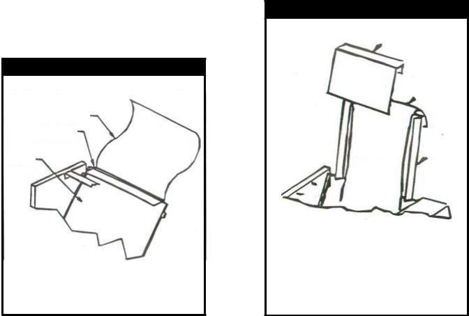
2.ASSEMBLY (REFER TO ILLUSTRATIONSABOVE)
a)Lay the toaster on its side and install the four Adjustable Legs (Item 1) in threaded holes in base. Tighten legs with crescent wrench. The unit may be leveled by unscrewing the lower insert of each leg. Precise leveling is not required for proper operation of the toaster. Set the toaster upright.
CAUTION: DO NOT OPERATE THE TOASTER WITHOUT THE LEGS INSTALLED.
3.CONVEYOR INSTALLATION
M-83 Only:
Remove Butter Roller (Item 2) by pushing shaft to the left to disengage. Remove Butter Pan (Item 3) by lifting the pan up and off the supporting pins.
M-83/M-83D:
a)Remove Top Front Panel (Item 4A) by gripping the two black knobs while lifting up and slightly back. The Bottom Front Panel (Item 4B) can then be removed by grasping the top edge with one hand and pulling straight back. Hold the bottom with the other hand and lift up and toward the front; then slide panel down and out underneath the Butter Roller bushings.
b)Grasp Conveyor (Item 5) by the handles. Lower conveyor knobs into right and left Hangar Brackets (Item 6A/B). Gently push forward to engage gears.
CAUTION: THE CONVEYOR IS HEAVY. DO NOT DROP INTO POSITION. DROPPING MAY CAUSE DAMAGE TO GEARS.
c)Replace Bottom Front Panel (Item 4B), Top Front Panel (Item 4A), Butter Pan (Item :3) and
Butter Roller (Item 2)
M-91 :
a)The Conveyor (Item 5) is shipped in place and strapped down with nylon tie. To remove
nylon tie, follow steps b, c and d. |
. |
b)Remove Butter Roller (Item 2) by pushing shaft to the right to disengage. Remove Butter Pan (Item 3) by sliding toward the front of the unit, underneath the Butter Roller Bushings.
c)Remove Front Panel (Item 4) by gripping the top edge with one hand and the bottom edge with the other hand. Lift up to disengage slots in panel from retaining rods, then move forward and slide down and out underneath the Butter Roller Bushings.
d)Cut and remove the nylon tie securing the conveyor. (Note: To remove for cleaning, see "Disassembly" Instructions.)
e)Replace Front Panel (Item 4), Butter Pan (Item 3) and Butter Roller (Item 2).
M-95
a)The Conveyor (Item 5) is shipped in place and strapped down with nylon tie. To remove nylon tie, follow steps b, c, and d.
b)Remove Butter Roller (Item 2) by lifting left side of butter roller shaft. Remove Butter Pan by sliding toward the front of the unit, underneath the butter roller bushings.
4
c)Remove Top Front Panel (Item 4A) by gripping rear edge and lifting up. The Bottom Front Panel (Item 4B) can then be removed by holding the top edge with one hand and the bottom edge with the other hand, then lifting panel up.
d)Cut and remove the nylon tie securing the conveyor. (Note: to remove for cleaning, see "Disassembly" instructions.)
e)Replace Bottom and Top Front Panels (Items 4A& 4B), Butter Pan (Item 3) and Butter Roller (Item 2).
4.BUN CHUTE/FEEDER/SUPER FEEDER INSTALLATION
M-83/M-83D: Install Bun Chute/Feeder (Item 7) by fitting slots on each side onto back panel studs located at top rear of unit. .
M-91: Install Feeder/Super Feeder (Item 7) by sliding feeder support "legs" into channels located at top rear of unit.
5.INSTALLATION OF OPTIONAL PTFE SHEET FOR DRY OPERATION AND/OR INCREASED
EASE OF CLEANING |
|
NOTE: Apply light coating of oil to grill surface prior to installation of PTFE sheet. |
PT |
M-83 & M-91
a)Lay PTFE Sheet on flat surface. Measure approximately 2" from end of sheet. Notch corners as needed. Fold under 2" long flap. Crease PTFE Sheet at 2" fold.
b)Remove Super Feeder (bun chute). From rear of PTFE Sheet retainer bracket, slip 2" fold of PTFE Sheet under bracket. Bring balance of sheet forward and smooth sheet down against grill plate.
c)Reinstall Super Feeder bun chute.
M-83 & M-91
PTFE Sheet
PTFE Sheet
Retainer Bracket
Grill
Plate
M-95
a)Slide one' end of PTFE sheet beneath conveyor to bottom of grill plate.
b)Place other end of PTFE sheet over top edge of grill plate.
c)Install PTFE sheet retainer over PTFE sheet and grill plate.
M-95
M-83 PTFE Sheet Kit P/N 87449 |
M-95-2 PTFE Sheet Kit P/N 84177 |
M-91 PTFE Sheet Kit P/N 83764 |
M-91-3 PTFE Sheet Kit P/N 84176 |
5
LOCATION
.
1.Place the toaster on a flat surface and in such a way that the unit's vents are not blocked. Air must circulate under and through the vents provided on the base, right side (M-83, M83D, & M-95), left side (M-91) and rear of the unit.
2.Locate the unit near a wall receptacle of the proper configuration. DO NOT USE AN EXTENSION CORD. Plug the power supply cord into an outlet (receptacle) of the voltage specified on the unit's
rating plate. Outlets must be properly grounded.
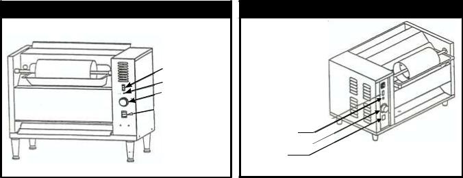
M-83 & M-95 Toaster
Motor Switch
Pilot Light
Temperature
Control

 Main Switch
M-91 Toaster
Motor Switch
Pilot Light
Temperature
Control
Main Switch
M-83 & M-91 OPERATING INSTRUCTIONS
A.PREPARATION
1.Warm-up Time: Turn the control knob to 400°F (number 8) or 450°F (number 9) using optional PTFE Sheet. Wait 15-25 minutes or until the pilot light cycles on and off twice.
2.Use of Oil: Any high-quality oil may be used in the Bun Grill Toaster. While health concerns have led to the decreased use of tropical cooking oils, coconut oil does caramelize when toasted to give the product an appetizing golden color. It also helps the product to reach and maintain the optimum serving temperature. Whereas some cooking oils tend to gum up, those designed for use in toasters will work throughout the day without the need to stop and clean the grill.
B.CONTROL PANEL
The face of the panel has two (2) Iighted rocker switches and a temperature control:
1.Main S witch - main power On/off.
2.Motor Switch - On/off switch turns both butter roller and conveyor on and off.
3.Temperature Control - Controls the temperature of the grill. The pilot light will stay on until the grill temperature has been attained and will then turn off. Allow .the pilot light to cycle twice so the unit is at stabilized temperature for toasting buns.
NOTE: During slow periods to conserve energy and prolong motor life, you may turn temperature control down to 150°F (66°C) and turn off motor switch.
4.Pilot Light - Glows when grill is on.
6
 Loading...