


R
INSTALLATION AND OPERATING INSTRUCTIONS
TOP MOUNT HOT FOOD WELLS
MODELS: HFW-2 thru 6 & HFW-2D thru 6D
&
SLIMLINE INSULATED HOT FOOD WELLS
MODELS: HFWS-2 thru 4
Models: HFW-2 thru 6 & HFW-2D thru 6D |
HFWS-2 thru 4 |
INTENDED FOR OTHER THAN HOUSEHOLD USE
RETAIN THIS MANUAL FOR FUTURE REFERENCE
WARNING: Improper installation, adjustment, alteration, service or maintenance can
! cause property damage, injury or death. Read the Installation, Operating and ! Maintenance Instructions thoroughly before installing or servicing this equipment.
This equipment has been engineered to provide you with year-round dependable service when used according to the instructions in this manual and standard commercial kitchen practices.
Phone: |
+1 |
(214) 421-7366 |
P/N 79967133 8/08 |
|
|||
Fax: |
+1 |
(214) 565-0976 |
APW WYOTT |
Toll Free: +1 |
(800) 527-2100 |
||
Website: www.apwwyott.com |
729 Third Avenue |
||
E-mail: |
info@apwwyott.com |
Dallas, TX 75226 |
|
1

TABLE OF CONTENTS
Safety Precautions |
2 |
General Information |
4 |
General Troubleshooting |
4 |
Installation |
4 |
General & Electrical Specifications HFW-2 thru HFW-6 |
5 |
General & Electrical Specifications HFWS-2 thru HFWS-4 |
6 |
Operation & Cleaning |
6 |
Parts List w/Exploded View HFW-2 thru HFW-6 (Thermostat Control) |
8 |
Parts List w/Exploded View HFW-2 thru HFW-6 (Infinite Control) |
10 |
Parts List w/Exploded View HFWS-2 thru HFWS-4 (Thermostat & Infinite Control) |
12 |
Wiring Diagrams |
14 |
Warranty |
16 |
IMMEDIATELY INSPECT FOR SHIPPING DAMAGE
All containers should be examined for damage before and during unloading. The freight carrier has
assumed responsibility for its safe transit and delivery. If equipment is received damaged, either apparent
or concealed, a claim must be made with the delivering carrier.
A)Apparent damage or loss must be noted on the freight bill at the time of delivery. It must then be signed by the carrier representative (Driver). If this is not done, the carrier may refuse the claim. The carrier can supply the necessary forms.
B)Concealed damage or loss if not apparent until after equipment is uncrated, a request for inspection must be made to the carrier within 15 days. The carrier should arrange an inspection. Be certain to hold all contents and packaging material.
Installation and start-up should be performed by a qualified installer who thoroughly read, understands and follows these instructions.
APW Wyott takes pride in the design and quality of our products. When used as intended and with proper care and maintenance, you will experience years of reliable operation from this equipment. To ensure best results, it is important that you read and follow the instructions in this manual carefully.
Installation and start-up should be performed by a qualified installer who thoroughly read, understands and follows these instruction.
If you have questions concerning the installation, operation, maintenance or service of this product, write Technical Service Department: APW/Wyott Foodservice Equipment Company, 729 Third Avenue, Dallas, TX 75226 .
SAFETY PRECAUTIONS
Before installing and operating this equipment be sure everyone involved in its operation are fully trained and are aware of all precautions. Accidents and problems can result by a failure to follow fundamental rules and precautions.
The following words and symbols, found in this manual, alert you to hazards to the operator, service personnel or the equipment. The words are defined as follows:
! |
DANGER: This symbol warns of imminent hazard which will result in serious injury or death. |
! |
|
|
|
! |
WARNING: This symbol refers to a potential hazard or unsafe practice, which could result in |
! |
serious injury or death. |
||
|
|
|
|
CAUTION: This symbol refers to a potential hazard or unsafe practice, which may result in minor or |
! |
! moderate injury or product or property damage. |
||
|
|
|
! |
NOTICE: This symbol refers to information that needs special attention or must be fully understood |
! |
even though not dangerous. |
||
2

THIS MANUAL SHOULD BE RETAINED FOR FUTURE REFERENCE
CAUTION: These models are designed, built, and sold for commercial use. If these models are positioned so the general public can use the equipment make sure that cautions, warnings, and
! operating instructions are clearly posted near each unit so that anyone using the equipment will ! use it correctly and not injure themselves or harm the equipment.
! |
WARNING: Check the data plate on this unit before installation. Connect the unit only to the voltage |
! |
and frequency listed on the data plate. Connect only to 1 or 3 phase as listed on the data plate. |
WARNING: In Europe, appliance must be connected by an earthing cable to all other units
! in the complete installation and thence to an independent earth connection in compliance ! with EN 60335-1 and/or local codes
WARNING: For your safety do not store or use gasoline or other flammable vapors or liquids in the
! vicinity of this or any other appliance. Keep the area free and clear of combustibles. (See ANZI ! Z83.14B, 1991)
! |
NOTICE: This equipment has been engineered to provide you with year round dependable service |
! |
when used according to the instructions in this manual and standard commercial kitchen practices. |
WARNING: Install per the spacing requirements listed in the installation section of this manual. We strongly recommend having a competent professional install the equipment. A licensed electrician
! should make the electrical connections and connect power to the unit. Local codes should always ! be used when connecting these units to electrical power. In the absence of local codes, use the latest version of the National Electrical Code.
WARNING: This device should be safely and adequately grounded in accordance with local codes, or in the absence of local codes, with the National Electrical code, ANSI/NFPA 70, Latest
! Edition to protect the user from electrical shock. It requires a grounded system and a dedicated ! circuit, protected by a fuse or circuit breaker of proper size and rating. Canadian installation must comply with the Canadian Electrical Code, CSA C22.2, as applicable
WARNING: An earthing cable must connect the appliance to all other units in the complete |
! |
! installation and from there to an independent earth connection. |
NOTICE: Local codes regarding installation vary greatly from one area to another. The National Fire Protection Association, Inc. states in its NFPA96 latest edition that local codes are “Authority
! Having Jurisdiction” when it comes to requirement for installation of equipment. Therefore, ! installation should comply with all local codes.
! |
WARNING: Unit is not waterproof. Do not submerge in water. Do not operate if it has been |
! |
submerged in water. Do not clean the unit with a water jet. |
IMPORTANT FOR FUTURE REFERENCE
Please complete this information and retain this manual for the life of the equipment. For Warranty Service and/or Parts, this information is required.
Model Number |
Serial Number |
Date Purchased |
3
GENERAL INFORMATION
General Installation:
1.Always clean equipment thoroughly before first use. (See general cleaning instructions.)
2.Check rating label for your model designation & electrical rating.
3.For best results, use stainless steel countertops.
4.All dimensions in parenthesis in centimeters, unless noted.
General Operating Instructions:
1.All food service equipment should be operated by trained personnel.
2.Do not allow your customers to come in contact with any surface labeled "CAUTION HOT."
3.Where applicable: Never pour cold water into dry heated units.
4.Where applicable, do not cook, warm or hold food directly in liner pans (well pans). Always use steam table pans/insets, etc.
5.Never hold food below 150°F (66°C)
Wet set-up and operation procedures:
1.Add hot water 120°-140°F (50°-60°C) to well pan: (12 x 20) use: 3.75 Quarts (15 Cups) (3.5 Litres)
2.Turn thermostat control to “10” setting or if equipped with infinite control to “7” or “High”. Preheat for approximately 30 minutes.
3.Place covered inset with preheated product into well.
4.Re-adjust control after another 30 minutes of operation to acquire desired temperature depending on the amount and thickness of product.
5.Keep inset/steamtable pan(s) covered to maintain ideal serving temperature.
6.Do not let well run dry.
General Cleaning Instructions:
1.NEVER clean any electrical unit by immersing it in water. Turn off before surface cleaning.
2.Always clean equipment thoroughly before first use. Clean unit daily. Use warm, soapy water (except where noted on charts). Mild cleansers and PLASTIC scouring pads may be used to remove baked-on food and water scale.
3.Turn off electrical units before cleaning or servicing. All service should be performed by an APW Wyott authorized service agency.
GENERAL TROUBLESHOOTING
Always Ask & Check: 1. Is the unit connected to a live power source?
2.Check circuit breaker.
3.Is power switch on & pilot light glowing?
4.Check rating label. Are you operating unit on proper voltage?
INSTALLATION
1.Follow General Installation Instructions on page 4 (above).
2.Make applicable Cut-Out per below table. Note: Unit is designed for installation in stainless steel tops.
3.Apply putty tape to underside perimeter of the well rim outer edge.
4.Apply a 1/4" (.6) bead of silicone sealant adjacent to the putty tape on the well flange.
5.Drop well into opening from the top and push down until entire perimeter of rim is flush with the counter surface.
6.From below the counter surface insert an #8 to #10 (20 to 25 cm) flat tip screwdriver into the locking ring tab slots and twist in a clockwise motion to lock well in place.
7.Trim excess putty and sealant from around well rim.
8.Mount control to front panel using hardware. Maintain 4" (10.2) clearance between well and front panel.
9.Check nameplate for proper voltage. Connect power.
Note: Electrically connect units to comply with local and NEC codes.
4
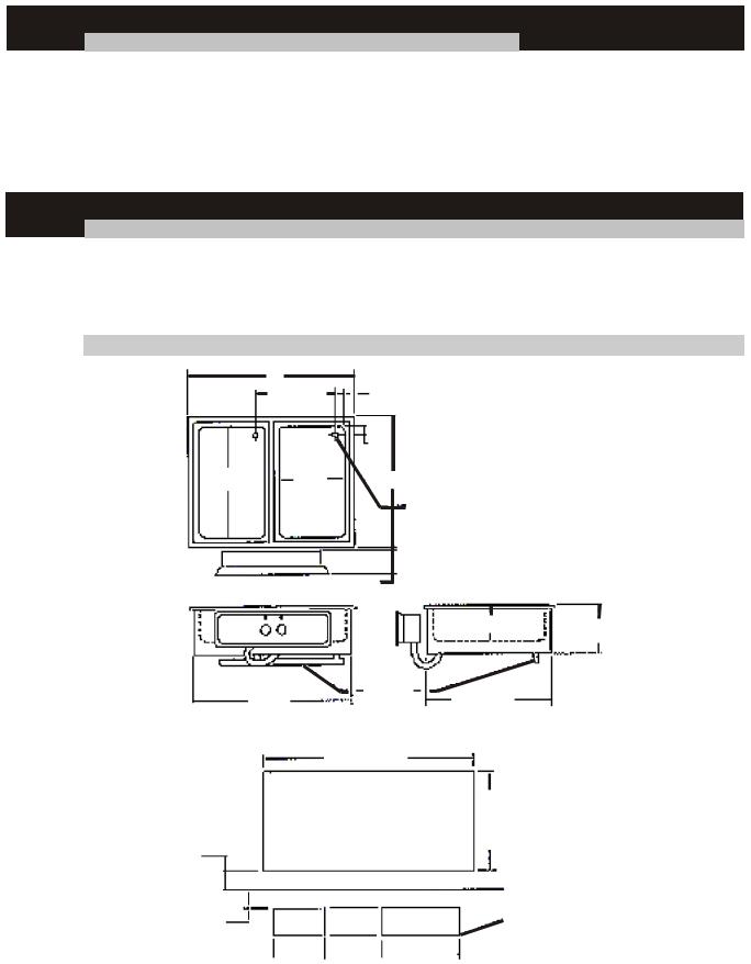
GENERAL SPECIFICATIONS (All Models HFW)
Model |
Outside Dimensions |
Cut Out |
B |
|
Control Cut Out |
Shipping Weight |
||||
|
||||||||||
|
A |
B |
C |
A |
|
|
|
|
|
|
|
|
|
|
|
|
|||||
HFW-2 Well |
29.750 (75.6) |
23.438 (59.5) |
28.122 (71.4) |
28.622 (72.7) |
|
22.500 (57.2) |
|
See Above |
89 |
Lbs. (40.4Kg) |
HFW-3 Well |
44.125 (112.1) |
23.438 (59.5) |
42.497 (107.9) |
42.997 (109.2) |
|
22.500 (57.2) |
|
See Above |
139 |
Lbs. (63.0Kg) |
HFW-4 Well |
58.500 (148.6) |
23.438 (59.5) |
56.872 (144.4) |
57.372 (145.7) |
|
22.500 (57.2) |
|
See Above |
169 |
Lbs. (76.7Kg) |
HFW-5 Well |
72.875 (185.1) |
23.438 (59.5) |
71.247 (181.0) |
71.747 (182.2) |
|
22.500 (57.2) |
|
See Above |
199 Lbs. (90.3Kg) |
|
HFW-6 Well |
87.250 (221.6) |
23.438 (59.5) |
85.622 (217.5) |
86.122 (218.7) |
|
22.500 (57.2) |
|
See Above |
251 |
Lbs. (113.9Kg) |
ELECTRICAL SPECIFICATIONS
Model |
|
Electrical Ratings |
|
|
Electrical Ratings |
|
|||
|
Volts |
Watts |
Amps |
Max Amps (3ph) |
Volts |
Watts |
Amps |
|
Max Amps (3ph) |
HFW-2 Well |
208/240 |
2400/3200 |
11.5/13.3 |
6.7/7.7 |
208 |
3200 |
15.4 |
|
8.9 |
HFW-3 Well |
208/240 |
3600/4800 |
17.3/20.0 |
10.0/11.6 |
208 |
4800 |
23.1 |
|
13.4 |
HFW-4 Well |
208/240 |
4800/6400 |
23.1/26.7 |
13.3/15.4 |
208 |
6400 |
30.8 |
|
17.8 |
HFW-5 Well |
208/240 |
6000/8000 |
28.8/33.3 |
16.7/19.2 |
208 |
8000 |
38.5 |
|
22.3 |
HFW-6 Well |
208/240 |
7200/9600 |
34.6/40.0 |
20.0/23.2 |
208 |
9600 |
46.2 |
|
26.7 |
|
1200W Each @ 208, 1600W Each @ 240V |
|
1600W Each @ 208 |
|
|||||
A
14.750 (37.5)
1.688
(4.3)
11.875
19.875 (50.50) B
(30.0)
Models w/Drain (See Notes)
3.875 (9.80)
|
|
|
|
|
|
|
|
|
|
|
|
|
|
|
|
|
|
|
|
|
|
|
|
|
|
6.250 (15.90) |
8.639 (21.90) |
||||||||||
|
|
|
|
|
|
|
|
|
|
|
|
|
|
|
|
|
|
|
Manifold |
|
|
|
|
|
|
|
|
|
|
|
|
|
|
|
|||
|
|
|
|
|
|
|
|
|
C |
|
|
|
|
|
|
|
|
|
|
|
|
21.875 |
|
|
|
|
|||||||||||
|
|
|
|
|
|
|
|
|
|
|
|
|
|
|
|
|
|
|
|
|
|
|
|
|
|||||||||||||
|
|
|
|
|
|
|
|
|
|
|
|
|
|
|
|
|
|
|
|||||||||||||||||||
|
|
|
|
|
|
|
|
|
|
|
|
|
|
|
|
|
|
|
|
|
|
|
(55.6) |
|
|
|
|
||||||||||
|
|
|
|
|
|
|
|
|
|
|
|
|
|
|
|
|
|
|
|
|
|
|
|
|
|
|
|
|
|
||||||||
4.0 (10.2) |
|
|
|
|
|
|
|
|
|
|
|
|
|
|
|
|
|
A |
|
|
|
|
|
|
|
|
|
|
|
|
|
|
|
|
|
|
|
|
|
|
|
|
|
|
|
|
|
|
|
|
|
|
|
|
|
|
|
|
|
|
|
|
|
|
|
|
|
|
|
|
|
|
|||
|
|
|
|
|
|
|
|
|
|
|
|
|
|
|
|
Cut-Out |
|
|
|
|
|
|
|
|
|
|
|||||||||||
|
|
|
|
|
|
|
|
|
|
|
|
|
|
|
|
|
|
|
|
|
|
|
|
|
|
||||||||||||
|
|
|
|
|
|
|
|
|
|
|
|
|
|
|
|
|
|
|
B |
|
|
||||||||||||||||
Minimum |
|
|
|
|
|
|
|
|
|
|
|
|
|
|
|
|
|
|
|
|
|
|
|
|
|
|
|
|
|
|
|
||||||
|
|
|
|
|
|
|
|
|
|
|
|
|
|
|
|
|
|
|
|
|
|
|
|
|
|
|
|
|
|
|
|||||||
from |
|
|
|
|
|
|
|
|
|
|
|
|
|
|
|
|
|
|
|
|
|
|
|
|
|
|
|
|
|
|
|
||||||
Control Edge |
|
|
|
|
|
|
|
|
|
|
|
|
|
|
|
|
|
|
|
|
|
|
|
|
|
|
|
|
|
|
|
|
|
|
|
|
|
|
|
|
|
|
|
|
|
|
|
|
|
|
|
|
|
|
|
|
|
|
|
|
|
|
|
|
|
|
|
|
|
|
|||||
|
|
|
|
|
|
|
|
|
|
|
|
|
|
|
|
|
|
|
|
|
|
|
|
|
|
|
|
|
|
|
|||||||
|
|
|
|
|
|
|
|
|
|
|
|
|
|
|
|
|
|
|
|
|
|
|
|
|
|
|
|
|
|
|
|
|
|
|
|
|
|
2.0 (6.1) Minimum |
|
|
|
|
|
|
|
|
|
|
|
Control Box |
|
|
|
|
|
|
|
|
3/8 (1.0) Dia. Holes |
||||||||||||||||
|
|
|
|
|
|
|
|
|
|
|
|
|
|
|
|
|
|
|
|||||||||||||||||||
|
|
|
|
|
|
|
|
|
|
|
5 5/8 |
|
(14.3) |
|
|
|
|
|
|
|
|
|
|
|
|
|
|||||||||||
|
|
|
|
|
|
|
|
|
|
|
|
|
|
|
|
|
|
|
|
|
|
|
|
||||||||||||||
|
|
|
|
|
|
|
|
|
|
|
|
|
|
|
|
|
|
|
|
|
|
|
|
||||||||||||||
|
|
|
|
|
|
|
|
|
|
|
|
|
|
|
|
|
|
|
|
|
|
|
|||||||||||||||
from Control Top |
|
|
9 13/16 |
|
|
|
|
|
|
|
19 7/8 (50.5) |
|
|
3, 4, 5 & 6 Well |
|
|
|||||||||||||||||||||
2 Well |
|
|
|
|
|
||||||||||||||||||||||||||||||||
|
|
|
|
|
|
|
|
|
|
|
|
||||||||||||||||||||||||||
|
|
|
|
|
|
|
|
|
(24.9) |
|
|
|
|
|
|
||||||||||||||||||||||
|
|
|
|
|
|
|
|
|
|
|
|
|
|||||||||||||||||||||||||
|
|
|
|
|
|
|
|
|
|
|
|
|
|
|
|
|
|
|
|
|
|
|
|
|
|
|
|
|
|
|
|||||||
5
 Loading...