

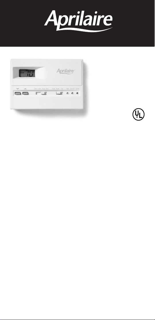
Aprilaire 8336 User Manual
IMPORTANT SAFETY INFORMATION
WARNING:
• Always turn off power at the main power source by unscrewing
fuse or switching circuit breaker to the off position before installing,
removing, cleaning, or servicing thermostat.
• Read all of the information in this manual before installing or
programming this thermostat.
• This is a 24V AC low-voltage thermostat. Do not install on voltages
higher than 30V AC.
• All wiring must conform to local and national building and electrical
codes and ordinances.
• Do not short (jumper) across terminals on the gas valve or at the
system control to test installation. This will damage the thermostat
and void the warranty.
1
2 Heat / 2 Cool Digital
Heat Pump
MODEL 8336
User’s Manual
Installation and
Operation
ELECTRONIC THERMOSTATS
®
Features
• Multi Stage heating and cooling control.
• Zone system compatible as a master thermostat.
• Multi-Colored LED indicators for system status.
• Low battery indicator.
• Fahrenheit/Celsius display option.
• Adjustable from 45°F (4°C) to 90°F (32°C).
• Accuracy within ± 1 degree.
• Adjustable temperature differential: 1-3 degrees F.
• Automatic heating shutdown if temperature exceeds 90°F (32°C).
Replacing Existing Thermostat
1. Turn off power to heating and cooling system.
2. Remove cover of old thermostat to expose wires.
Do not disconnect wires. (Fig. 1)
3. Label wires per Table 1.
Table 1
Old Label New Label Description
R, V-VR or VR-R R 24 VAC, Return
Y, Y1 or M Y Stage 1 Cooling/Heating
Circuit
O or R O Reversing Valve,
(Cooling Mode)
B B Reversing Valve
(Heating Mode)
F or G G Fan control relay
Y2 Y2 2nd Stage Cooling
Circuit
W1 or W2 or W-U W2 2nd Stage Heating
Control
L or X L System Monitor LED
E E Emergency Heating
Circuit
C, X or B C 24 VAC, Transformer
Common Side
*NOTE: This thermostat requires a 24V common wire for proper operation.
2
4. After labeling wires, remove wires from terminals.
5. Remove existing thermostat base from wall.
6. Refer to the following section for instructions on how to
install thermostat.
Installing the Model 8336 Thermostat
NOTE: For new installations, mount thermostat on inside wall, 4-5 feet
above the floor. Do not install behind a door, in a corner, near air vents, in
direct sunlight, or near any heat or steam generating fixtures. Installation
at these places will affect thermostat operation.
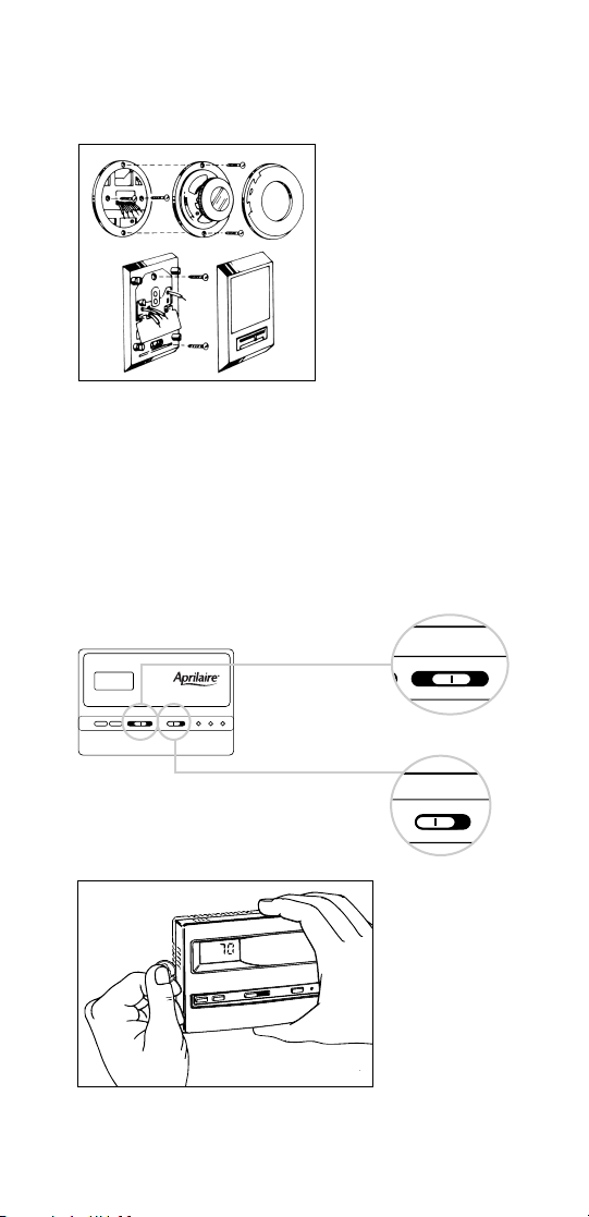
1. Turn power off to the heating
and cooling systems.
2. Place COOL-OFF-HEAT-EM
In OFF position.
3. Place FAN: AUTO-ON switch
Into AUTO position.
4. Remove the cover using a coin
or screwdriver.
3
COOL-OFF-HEAT-EM FAN: AUTO - ON
AUX
>
>
CHECK EMER
COOL-OFF-HEAT-EM
FAN: AUTO - ON
Figure 1
Figure 2
5. Place thermostat against the wall at desired location. Make sure
wires will feed through opening on base of thermostat.
6. Mark placement of mounting holes. See Fig. 3.
Set base aside.
figure 3
7. Drill the marked holes using a 3/16" drill bit. NOTE: Enclosed
plastic anchors do not require a drilled hole for drywall.
8. Tap plastic anchors into the wall.
9. Align base with plastic anchors and feed wires
through opening.
10. Secure base to wall with supplied screws.
4
Mounting Holes
Batteries NOT Required.
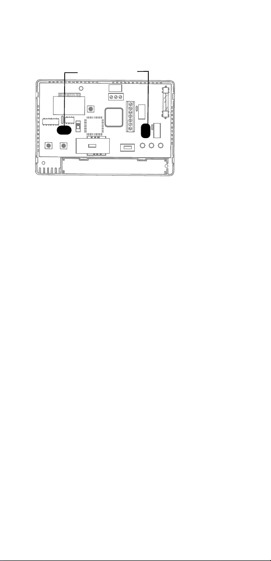
11. Connect wires to terminal strip. Refer to wiring diagrams on other
side of this sheet. Make sure wire connections are secure.
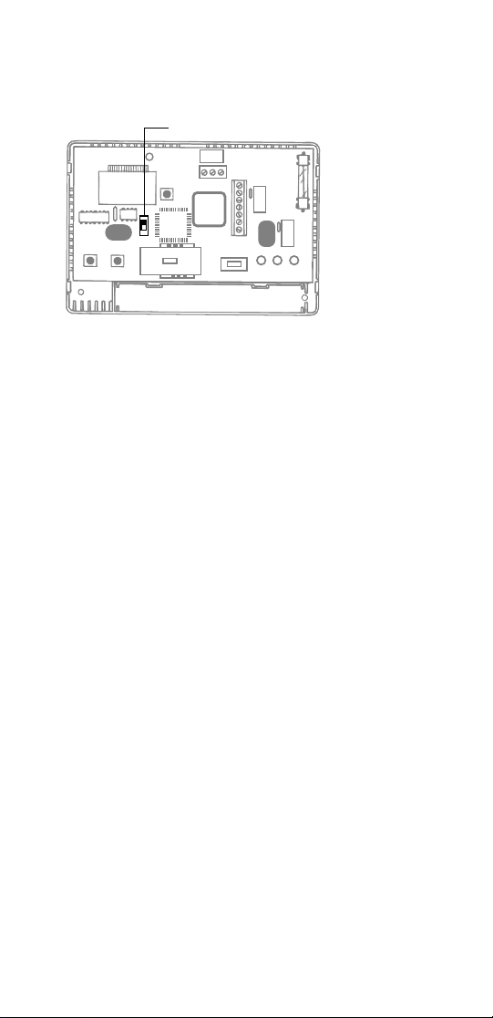
12. Put the °F/°C switch to either °F for Fahrenheit display
or °C for Celsius display readout.
figure 4
13. Replace cover onto thermostat by snapping into place.
14. Turn on power to system. Test thermostat as described
in the following section.
5
°F/°C Switch
Batteries NOT Required.
 Loading...