

Aprilaire 8265 Installation And Operation Manual
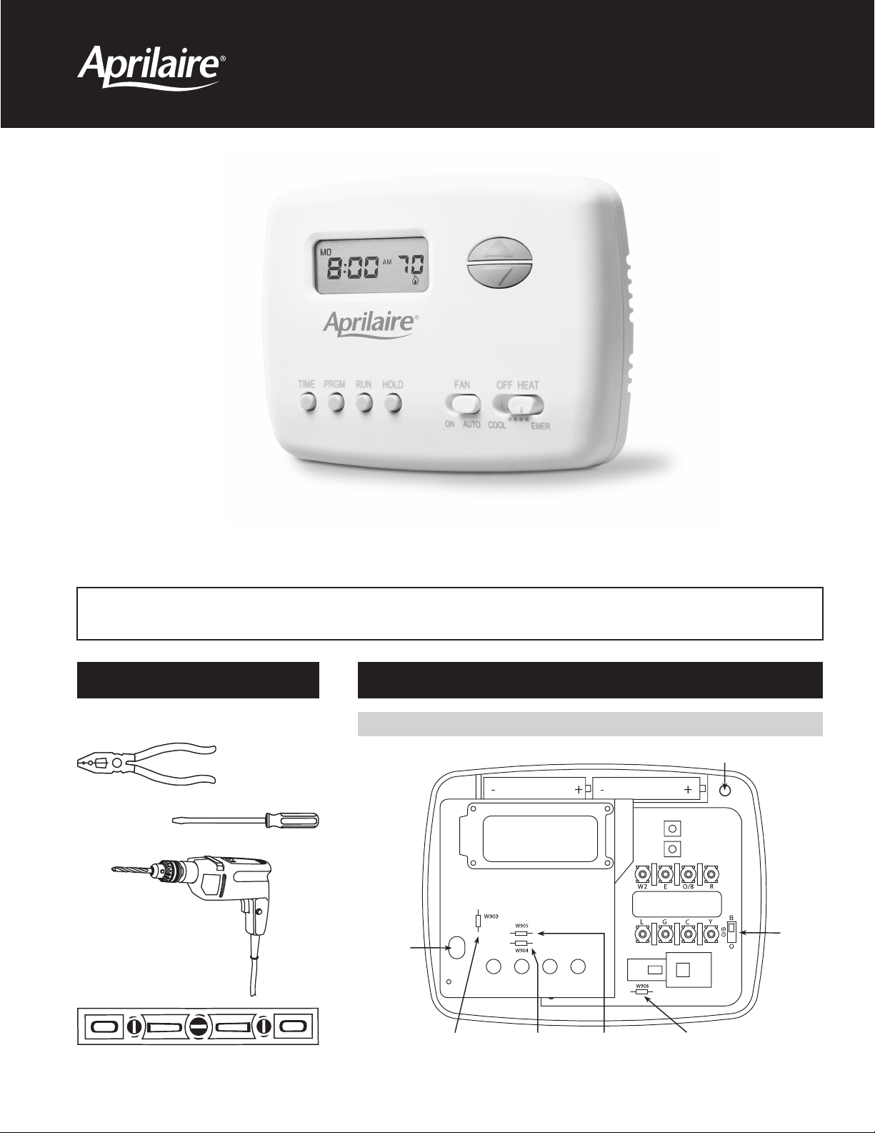
Programmable Thermostat
Model 8265 Installation and Operation Manual
5/2 Day Programmable Heat Pump Thermostat
Failure to follow and read all instructions carefully before installing or operating this control could cause personal
injury and/or property damage. If you have any questions, please call Research Products Corporation at (800) 334-6011.
PREPARATIONS
Assemble tools required as shown below.
Wire cutter/stripper
Flat blade
screwdriver
Electric or cordless
drill with 3/16 inch
drill bit, if needed.
THERMOSTAT DETAILS
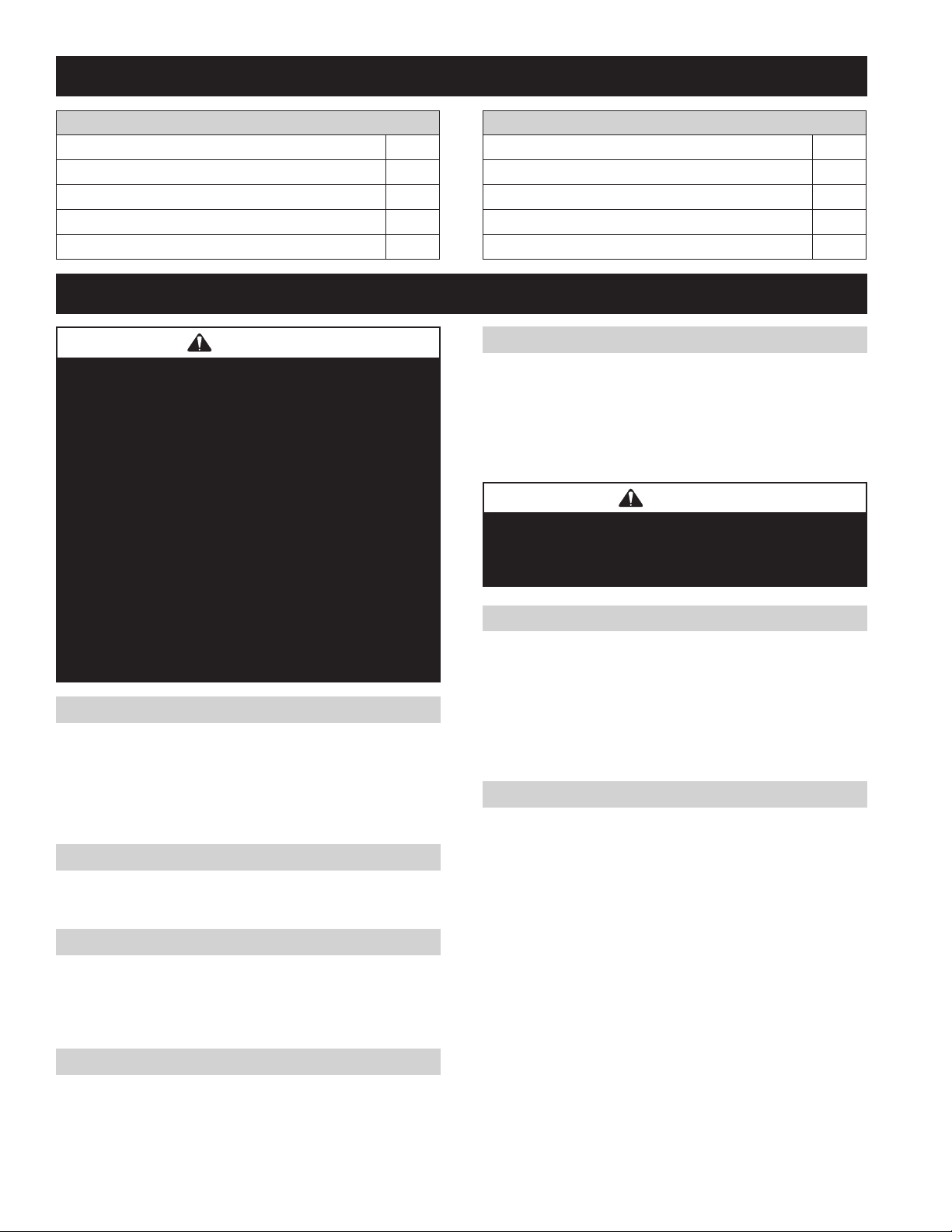
FIGURE 1 – Thermostat Base
Mounting
hole
Mounting hole
O/B
Terminal
Selection
Switch
Level
W903
Clip to Disable
Progressive Recovery
Feature
W904 Clip
for Celsius
instead of
Fahrenheit
W905 Clip for
Slow Cycle
instead of
Fast Cycle
W906 for Emergency Heat
Second Stage Fan Control.
Clip for Fan Control by Equipment
instead of by Thermostat.
THERMOSTAT APPLICATIONS
Description
Heat Pump (No Aux or Emergency Heat) Yes
Heat Pump (with Aux or Emergency Heat) Yes
Standard Heat & Cooling Systems No
Standard Heat Only Systems No
Millivolt Heat Only Systems – Floor or Wall Furnaces No
MOUNTING AND WIRING
WARNING
120 volts may cause serious injury from electrical
shock. Disconnect electrical power to the furnace & air
conditioner before starting installation. This thermostat
is not a 120 volt (line voltage) device.
Improper installation may cause serious injury from electrical
shock. This product must be installed by a qualifi ed
heating & air conditioning contractor in accordance with
NEC Standards and applicable local and state codes.
Do not use on circuits exceeding specifi ed voltage.
Higher voltage will damage control and could cause
shock or fi re hazard.
Do not short out terminals on gas valve or primary control
to test. Short or incorrect wiring will damage thermostat
and could cause personal injury and/or property damage.
Thermostat installation and all components of the system
shall conform to Class II circuits per NEC code.
ELECTRIC/GAS JUMPER (FAN OPTION)
If your emergency or auxiliary system will energize the blower, then
jumper W906 on the thermostat base must be cut (see Figure 1).
If your emergency or auxiliary heat system requires that the
thermostat energize the fan circuit, do not cut jumper W906.
If you are unsure of your application, contact a qualifi ed service person.
°F OR °C SELECTION
The factory default setting for temperature display is Fahrenheit.
If you want the temperature in Celsius, clip jumper W904.
FAST OR SLOW CYCLE SELECTION
The factory default setting is fast cycle, which cycles 1st stage with a
temperature swing of approximately 1.2°F and 2nd stage with 0.75°F.
If you prefer slow cycle, clip jumper W905. The 1st stage and 2nd
stage temperature swing will become 1.5°F and 1.2°F respectively.
PROGRESSIVE RECOVERY
This thermostat is set to operate with Progressive Recovery. This
causes the thermostat to start the heating or cooling system early to
have the room temperature reach the program setpoint at the time
the period is to start.
To disable Progressive Recovery, clip jumper W903 (see Figure 1).
2
Description
Standard Central Air Conditioning No
Gas or Oil Heat No
Electric Furnace No
Hydronic (Hot Water) Zone Heat – 2 Wires No
Hydronic (Hot Water) Zone Heat – 3 Wires No
O/B TERMINAL SELECTION SWITCH
The O/B switch on this thermostat is factory set to the “B” position.
This will accommodate the majority of heat pump applications which
require the changeover relay to be energized in HEAT. If the heat
pump being installed with this thermostat requires an “O” terminal
to energize the changeover relay in COOL, the O/B switch must be
moved to the “O” position.
CAUTION
Take care when securing and routing wires so they do
not short to adjacent terminals or rear of thermostat.
Personal injury and/or property damage may occur.
BATTERY LOCATION
This thermostat does not require batteries to operate. The 2 “AAA”
alkaline batteries are for the thermostat to remember the programming
if AC voltage is lost. If the display shows BATT when AC power is
not present, the batteries are low and should be replaced with fresh
“AAA” Energizer® alkaline batteries. To replace the batteries, install
the batteries along the top of the base (see Figure 1). The batteries
must be installed with the positive (+) ends to the right.
CHOOSE A LOCATION TO MOUNT THE THERMOSTAT
MOUNT THE THERMOSTAT…
• Approximately 5 feet above the fl oor. Refer to local codes for
compliance with the Americans with Disabilities Act (ADA).
• On an interior wall in a frequently occupied space where the
temperature is most representative of the zone being controlled
by the thermostat.
• At least 18 inches away from an outside wall.
DO NOT MOUNT THE THERMOSTAT…
• Behind doors, in corners or other dead air spaces.
• In direct sunlight, near lamps or other sources of heat.
• On an outside wall or any wall exposed to an unconditioned space
(a garage for example).
• In the airfl ow path of a supply register, in stairways or near
outside doors.
• On a wall where concealed pipes or ductwork will affect the
thermostat temperature accuracy.
• Near sources of electrical interference, such as arcing switch contacts.

ATTACH THERMOSTAT BASE TO WALL
1. Remove the packing material from the thermostat. Gently pull the
cover straight off the base. Forcing or prying on the thermostat will
cause damage to the unit. Loss of internal programs may result from
static discharge to thermostat circuit board. Please touch a grounded
metal object before handling the thermostat.
2. Connect wires beneath terminal screws on base using appropriate
wiring schematic (see Figures 2 through 4).
3. Place base over wire access hole in wall, level for appearance, and
mark mounting hole locations on wall using base as a template.
4. Move base out of the way. Drill mounting holes with 3/16 inch drill bit.
5. Fasten base loosely to wall using two mounting screws as shown
in Figure 1. Place a level against bottom of base, adjust until level,
and then tighten screws. (Leveling is for appearance only and will not
affect thermostat operation.) If you are using existing mounting holes,
or if holes drilled are too large and do not allow you to tighten base
snugly, use plastic screw anchors to secure sub-base.
FIGURE 2 – Typical wiring diagram for single transformer systems
Changeover
Relay*
* Changeover Relay is energized in COOL when O/B switch is in the “O” position
Changeover Relay is energized in HEAT when O/B switch is in the “B” position
** Jumper required to use a single Aux Heat for both Second Stage Heat and Emergency
Compressor
Contactor
Fan
Relay
Aux
Relay
(Stage 2)
6. Wire the thermostat. IMPORTANT! ENSURE THE POWER AT
THE HVAC EQUIPMENT IS OFF.
a. Make sure the fan switch is set to Auto and the Mode switch is
set to Off.
b. Strip 3” of cable insulation.
c. Strip 3/8” of insulation from each wire. Do not cut into the wire
when stripping insulation, as this can lead to eventual control
failure.
d. Secure the wires to the thermostat terminal strip according to
the wiring diagram for the model being installed (see Figures
2 through 4). Use a fl at screw driver with a 1/8” tip (terminal
screw driver). Use color coding where possible (i.e. red wire to
R terminal, white wire to W terminal, etc.).
e. Slide excess cable back into the wire entry wall opening and fi ll
the hole with insulation. Failure to seal the hole can cause drafts
to enter the thermostat and affect temperature sensing accuracy.
THERMOSTAT
See Note **
Emergency
Relay
SYSTEM
MONITOR
SWITCH
24 VAC
TRANSFORMER
SYSTEM
Hot
120 VAC
Neutral
(Class II)
FIGURE 3 – Typical wiring diagram for two transformer systems with NO safety circuits
If safety circuits are in only one of the systems, remove the transformer of the system with NO safety circuits.
CUT AND
TAPE OFF!
Hot
120 VAC
Neutral
* Changeover Relay is energized in COOL when O/B switch is in the “O” position
Changeover Relay is energized in HEAT when O/B switch is in the “B” position
** Jumper required to use a single Aux Heat for both Second Stage Heat and Emergency
24 VAC
Changeover
Relay*
Compressor
Contactor
Fan
Relay
NOTE
See Note **
Emergency
Aux
Relay
(Stage 2)
TWO COMMONS MUST
BE JUMPERED TOGETHER!
Relay
SYSTEM
MONITOR
SWITCH
Limit or
Safety
Switches
THERMOSTAT
SYSTEM
24 VAC
FIGURE 4 – Typical wiring diagram for two transformer systems with safety circuits in BOTH systems
SYSTEM
MONITOR
SWITCH
NOTE
COMMON
Switches
Limit or
Safety
Switches
Limit or
Safety
24 VAC
ACCESSORY
RELAY N.O.
CONTACT
COMMON
THERMOSTAT
SYSTEM
24 VAC
Auxiliary
Heating
Transformer
(Class II)
24 VAC 120 VAC
Heat Pump Transformer
(Class II)
120 VAC
The accessory relay scheme
is required when safety circuits
Limit or
Safety
Switches
Polarity must be observed. If the HOT side of the second transformer is jumpered to the COMMON side of the first transformer a short will be made.
Changeover
Relay*
Compressor
Contactor
* Changeover Relay is energized in COOL when O/B switch is in the “O” position
Changeover Relay is energized in HEAT when O/B switch is in the “B” position
** Jumper required to use a single Aux Heat for both Second Stage Heat and Emergency
Fan
Relay
Relay
(Stage 2)
Damage to equipment will occur when power is restored.
See Note**
Emergency
Relay
Aux
TWO COMMONS MUST
BE JUMPERED TOGETHER!
Hot
120 VAC
TRANSFORMER
Neutral
(Class II)
Limit or
Safety
HOT
Switches
NEUTRAL
NOTE
exist in both systems.
HOT
NEUTRAL
3
 Loading...