

Page 1
Service Source
Power Mac G5 (Late 2005)
Power Mac G5 (Late 2005 Dual 2.0/2.3 GHz) and
Power Mac G5 (Late 2005 Quad)
Updated: 2 November 2006
© 2005 Apple Computer, Inc. All rights reserved.
Page 2

Power Mac G5 (Late 2005)
Contents
Repair Extension Program
Power Mac G5 (Late 2005)Repair Extension Program 6
Program Overview 6
Eligible Products 6
Repair Strategy 9
Special CompTIA Code 10
Replacement Parts 10
Reimbursement Strategy 11
Basics
Overview 13
Gotchas 1
5
Serial Number Location 17
Liquid Cooling System (LCS) 18
General Safety Information 18
Safety Guidelines 18
Take Apart
General Information 21
Orientation 21
Tools 21
Special Tools 21
Power Cord 22
Parts Requiring Enclosure Replacement 22
Take Apart Procedures 22
Opening the Computer 23
Serial ATA Hard Drive 26
Serial ATA Hard Drive Data Cable 29
ii
Page 3

Optical Drive 34
Front Inlet Fan Assembly 38
Memory (DIMMs) 41
Graphics Card/PCI Express Card 44
Battery 50
AirPort Extreme/Bluetooth Combo Card and Runway Card 52
PCI Card Guide 55
Speaker/Fan Assembly 57
Ambient Board 59
Heatsink Cover 61
Rear Exhaust Fan Assembly 64
PCI Divider 68
Media Bay Fan 72
Processor Inlet Frame (Dual 2.0/2.3 GHz) 75
Processor (Dual 2.0/2.3 GHz) 77
Processor Inlet Frame (Quad) 83
Processor (Quad) 85
Processor Support Bar and Cable 103
Front Panel Board 106
Power Button 109
Logic Board 112
Antenna Board and Cables 120
Power Supply 126
Air Deector Sensor Board 132
Troubleshooting
General Information 136
DDR2 Memory 136
iii
Page 4

PCI Express Cards 137
Thermal Calibration 138
Resetting the Logic Board 138
Power-On Self Test: RAM and Processor Verication 139
Diagnostic LEDs 139
Power Supply Verication 141
Symptom Charts 144
How to Use the Symptom Charts 144
Startup Failures 144
Fans 148
Other Failures 149
Upgrades
AirPort Extreme/Bluetooth Combo Card and Runway Card 152
Views
Exploded Views 156
Exploded View 1 156
Exploded View 2 157
Screw Matrix 158
Internal Views 160
Overview 160
Logic Board 161
External Views 162
Front View 162
Rear View 163
iv
Page 5

Service Source
Repair Extension Program
Power Mac G5 (Late 2005)
© 2005 Apple Computer, Inc. All rights reserved.
Page 6

Power Mac G5 (Late 2005) Repair Extension Program
The Power Mac G5 (Late 2005) Repair Extension Program (REP) for Power Supply Issues covers
repairs for Power Mac G5 (Late 2005) computers exhibiting power-related issues due to specic
component failure within the computer’s power supply. If a Power Mac G5 (Late 2005) computer
fails to start up after the power button has been pressed and the computer’s serial number is
within the ranges noted below, the computer may be eligible for repair, free of charge to the
customer. There are no known safety issues caused by this component failure.
Program Overview
The Power Mac G5 (Late 2005) REP for Power Supply Issues covers Power Mac G5 (Late 2005)
models with a 1 KW AcBel power supply that exhibit one of the following power symptoms:
Computer will not start up after the power button is pressed
•
No LED activity
•
The computers must also fall within the eligible number ranges noted below. If these conditions
are met, the power supply should be replaced under this program.
The REP covers aected Power Mac G5 (Late 2005) computers for up to two years from the
original date of purchase, even if a computer is out of warranty. This worldwide Apple program
does not extend the standard warranty coverage of a computer. Apple will continue to evaluate
the repair data and will provide further repair extensions as needed.
Note: Customers are responsible for the repair cost of any damage caused by accident or misuse,
or for issues that do not relate directly to the specic power supply issues covered by this REP.
Eligible Products
The program is available for Power Mac G5 (Late 2005) computers that were sold between
approximately October 2005 and August 2006 and have a 1 KW AcBel power supply.
Eligible computers must meet the following conditions:
The computer exhibits one of the symptoms described in “Program Overview.”
•
The computer’s serial number falls within a specic range.
•
The power supply label lists AcBel as the manufacturer.
•
Power Mac G5 (Late 2005) Repair Extension Program for Power Supply Issues 6
Page 7
Serial Number Identication
To identify an eligible Power Mac G5 (Late 2005) computer, rst check the computer’s serial
number. Eligible computers have serial numbers with the rst ve digits falling within one of the
ranges noted below:
CK539xxxxxx – CK608xxxxxx
•
G8539xxxxxx – G8608xxxxxx
•
YM539xxxxxx – YM608xxxxxx
•
RM539xxxxxx – RM608xxxxxx
•
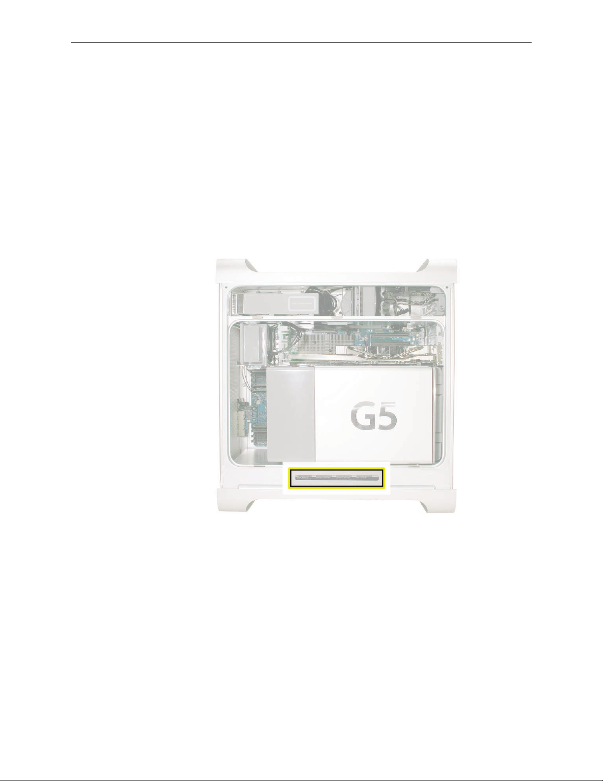
All Power Mac G5 (Late 20005) computer serial numbers are located directly below the air
deector inside the side access panel.
Power Supply Identication
If the computer’s serial number falls within the eligible range, you must then inspect the power
supply itself to determine if it is an AcBel power supply. After removing the power supply from
the enclosure, check the label on the bottom of the power supply.
Important: Before removing a power supply, inform the customer that a more thorough
inspection will be required to determine if the computer qualies for the REP. If the computer
does not qualify, contact the customer for resolution.
Power Mac G5 (Late 2005) Repair Extension Program for Power Supply Issues 7
Page 8
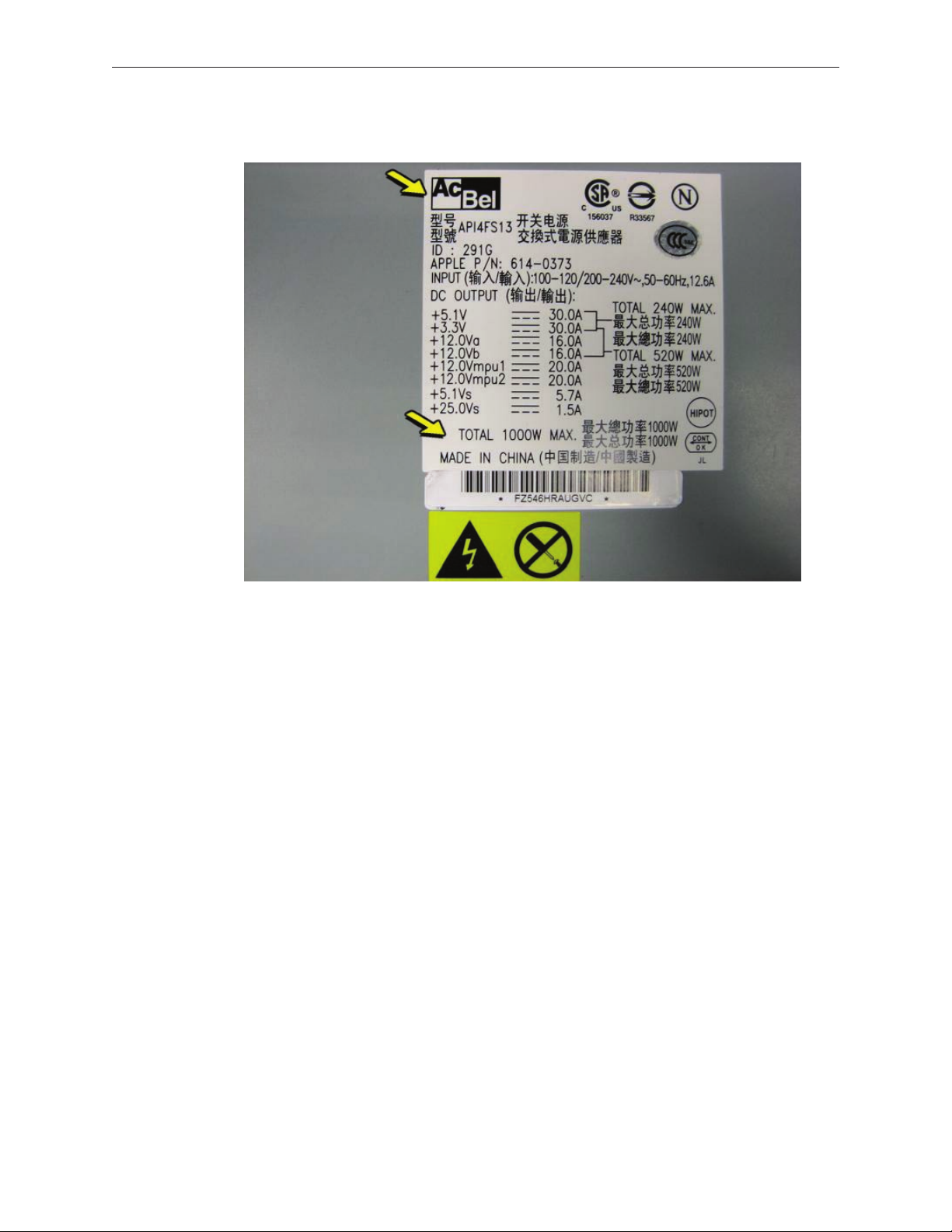
The AcBel label looks like this. Make sure the label lists both “AcBel” and “1000W.”
Excluded Repairs
Customers are responsible for the repair cost of any damage caused by accident or misuse. For
example, computers that show signs of having been dropped or of liquid spills into the case are
not eligible for the Power Mac G5 (Late 2005) REP.
Customers are also responsible for issues that do not relate directly to the specic power supply
issues covered by this program. For example, if a Power Mac G5 (Late 2005) computer is taken
to an Apple service provider with a power supply failure eligible under the program and a hard
drive issue, Apple will cover the power supply repair, but the cost of repairing the hard drive is
the customer’s responsibility.
Power Mac G5 (Late 2005) Repair Extension Program for Power Supply Issues 8
Page 9

Repair Strategy
Required service parts for this program are available so that certied technicians may repair
eligible Power Mac G5 (Late 2005) computers at an Apple service provider location. Repairs
completed for this program are exempt from the AppleCare Service Excellence program.
Customers are responsible for transportation costs to eligible service providers and retail stores.
Asia-Pacic, Canada, Europe (except IMCs), Japan, United States
Warranty Repairs
If a Power Mac G5 eligible for this program is currently covered by an Apple warranty or
extended service agreement, service providers should create the repair in the usual manner.
However, it is extremely important that you select the specic CompTIA code created for this
program (see “Special CompTIA Code”).
Out-of-Warranty Repairs
Until further notice, Apple asks that service providers in all regions that use GSX select the “Mark
for Review” checkbox on all out-of-warranty carry-in repairs created for Power Mac G5 computers
eligible for coverage under this repair extension program. In addition, it is extremely important
that you select the specic CompTIA code created for this program (see “Special CompTIA Code”).
Apple Retail
For the repair to be covered, Mac Genii should make the following selections in GCRM to ensure
the Power Mac G5 (Late 2005) Power Supply REP CompTIA code is assigned to the in-store repair:
Service Type: In-store Repair
Reason for Service: No Power
Component: Power, Video, as appropriate
Issue: Power Mac G5 (Late 2005) Power Supply Issues REP
CompTIA Modier: select most appropriate
For out-of-warranty computers, check the Override Warranty box in the Coverage section
of GCRM and select “Quality Program” for the reason. To generate the QP code, click on the
magnifying glass icon and select the Quality Program code for Power Mac G5 (Late 2005).
European IMCs
For repairs covered under the Power Mac G5 (Late 2005) REP for Power Supply Issues, IMCs in
Europe must order power supplies as stock parts using the part numbers listed above. To receive
credit for the covered power supplies, IMCs must request an RMA number from the SPS team and
return the defective parts to Apple with the RMA number.
Power Mac G5 (Late 2005) Repair Extension Program for Power Supply Issues 9
Page 10

Latin America
Latin American service providers should order parts for this repair extension program in the usual
manner. Service providers submitting a warranty claim should select “Quality Programs” as the
claim type and ensure the defective power supply’s serial number is entered in the Defective SN
eld.
Special CompTIA Code
Apple has created the following CompTIA code to use for repair on Power Mac G5 (Late 2005)
computers eligible under the Power Mac G5 (Late 2005) REP for Power Supply Issues.
Use CompTIA Code 663: PMG5 (Late 2005) Power Supply REP when replacing a power
supply under the Power Mac G5 (Late 2005) REP, whether or not the computer is covered by
warranty or an extended service agreement.
Japan (Mail-In Repairs Only)
Service providers in Japan who create a mail-in repair for Power Mac G5 (Late 2005) computers
eligible under the Power Mac G5 (Late 2005) REP for Power Supply Issues should select one of the
following two CompTIA codes:
Use CompTIA Code 663: PMG5 (Late 2005) Power Supply REP for power supply repairs
•
covered under the Power Mac G5 (Late 2005) REP for Power Supply Issues.
Use CompTIA Code 664: PMG5 (Late 2005) Power Supply REP Multiple Issues for products
•
exhibiting the symptoms listed above, but requiring repairs in addition to those covered by
the Power Mac G5 (Late 2005) REP for Power Supply Issues.
Replacement Parts
The only part eligible to be replaced under this repair extension program is the 1 KW AcBel
power supply, part number 661-3738.
Power Mac G5 (Late 2005) computers with quad 2.5 GHz processors must use the 1 KW power
supply as the replacement part. However, if you are repairing a 1 KW power supply in a Power
Mac G5 (Late 2005) computer with either dual 2 GHz or dual 2.3 GHz processors, you may use the
710 W power supply, part number 661-3737, as the replacement part. The following table shows
the replacement options:
Conguration Original Power Supply Replacement Power Supply
Quad 2.5 GHz 661-3738 661-3738
Dual 2.3 GHz 661-3738 661-3737 or 661-3738
Dual 2.0 GHz 661-3738 661-3737 or 661-3738
The parts listed above are the only approved power supply replacements covered under the
Power Mac G5 (Late 2005) REP for Power Supply Issues. Apple will accept 1 KW KBB power
supplies, part number 661-3738, in exchange for 710 W power supplies ordered with part number
661-3737.
Power Mac G5 (Late 2005) Repair Extension Program for Power Supply Issues 10
Page 11

Apple will charge service accounts for any parts ordered for repairs involving units eligible for
the Power Mac G5 (Late 2005) REP that are not related to this program and are not covered by
warranty or an extended AppleCare service agreement.
Reimbursement Strategy
Apple is aware that some customers may have paid for out-of-warranty repairs that now qualify
under this program. If a customers’ Power Mac G5 (Late 2005) computer was repaired out of
warranty and he/she believes the repair qualied under the Power Mac G5 (Late 2005) REP for
Power Supply Issues, Apple will review the claim and determine if the customer qualies for
reimbursement of the repair cost.
If the claim is determined to be eligible for repair under the Power Mac G5 (Late 2005) REP, Apple
will reimburse your customer directly.
Apple will work with service providers to inform aected customers (where contact information
is available) about details on the reimbursement process. If your service location has conducted
any out-of-warranty repairs that are eligible under this program, Apple will contact you in the
near future to coordinate communications to aected customers.
Note: Service that was performed to repair damage caused by accident or misuse is not covered
under this program.
Power Mac G5 (Late 2005) Repair Extension Program for Power Supply Issues 11
Page 12
Service Source
Basics
Power Mac G5 (Late 2005)
© 2005 Apple Computer, Inc. All rights reserved.
Page 13
Overview
Power Mac G5 (Late 2005) is the third generation of Power Mac G5 computers. It leverages the G5
architecture with the following new features:
G5 dual core processor (two processors on one chip): The Power Mac G5 (Late 2005 Dual
•
2.0 GHz/2.3 GHz) models use a single dual-core PowerPC G5 processor for dual processor
function. The Power Mac G5 (Late 2005 Quad 2.5 GHz) model uses two dual-core PowerPC
G5 processors for quad processor power.
533 MHz DDR2 main memory
•
PCI Express 16x video support
•
PCI Express 4x and 8x expansion support
•
Two enhanced 1GB Ethernet ports (supporting jumbo frames) on the back panel
•
Three USB 2.0 ports on the back panel
•
Combination Airport Extreme/Bluetooth card (CTO option)
•
External Apple USB modem (CTO option)
•
Diagnostic LEDs on logic board
•
Power Mac G5 (Late 2005) Basics 13
Page 14
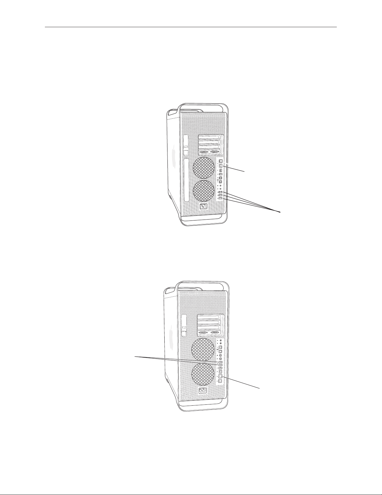
Differentiating the Power Mac G5 (Late 2005)
Gigabit Ethernet Ports (2)
USB 2.0 Ports (3)
USB 2.0 Ports (2)
Gigabit Ethernet Port
While Power Mac G5 (Late 2005) computers look similar to earlier Power Mac G5 models, you can
easily dierentiate the Power Mac G5 (Late 2005) by checking the back panel. Power Mac G5 (Late
2005) computers include two Gigabit Ethernet ports and three USB 2.0 ports, as illustrated below.
Power Mac G5 (Late 2005)
Earlier models include just one Gigabit Ethernet port and two USB 2.0 ports.
Earlier Power Mac G5 Models
Power Mac G5 (Late 2005) Basics 14
Page 15

Gotchas
Although the Power Mac G5 (Late 2005) computer looks similar to earlier Power Mac G5 models,
there are a number of signicant service and support dierences. Before troubleshooting or
servicing a Power Mac G5 (Late 2005), make sure you are familiar with the following points.
DDR2 memory: The Power Mac G5 (Late 2005) computer uses both ECC and NECC DDR2 DIMMs.
Refer to “DDR2 Memory” in the Troubleshooting chapter for more information about identifying
and installing these DIMMs.
PCI Express expansion slots: The Power Mac G5 (Late 2005) contains four PCI Express expansion
slots for graphics and other expansion cards. Refer to “PCI Express Cards” in the Troubleshooting
chapter for more information.
Graphics cards: Note the following dierences in Power Mac G5 (Late 2005) graphics cards:
Because Power Mac G5 (Late 2005) logic boards use PCI Express technology for all expansion
•
slots, AGP graphics cards and all earlier PCI cards are not compatible with these computers.
Graphics cards for the Power Mac G5 (Late 2005) have two DVI connectors.
•
Some cards ship with an adapter for connecting two DVI monitors.
•
The NVIDIA Quadro FX 4500 graphics card requires a new internal booster power cable. Refer
•
to the NVIDIA Quadro FX 4500 card take-apart procedure.
Special tools: Three special tools are required for servicing the Power Mac G5 (Late 2004)
computer. Refer to “Special Tools” in the Take Apart chapter.
Power cord: Because the power cord for the Power Mac G5 (Late 2005) is a special heavy-duty
cord specic to this model, power cords from earlier Power Mac G5 models are not compatible.
You can order the Power Mac G5 (Late 2005) power cord from GSX. For more information, refer to
“Power Cord” in the Take Apart chapter.
Diagnostic LEDs: To aid in troubleshooting the Power Mac G5 (Late 2005), a set of diagnostic
LEDs has been added to the Power Mac G5 (Late 2005) logic board. Refer to “Diagnostic LEDs” in
the Troubleshooting chapter for instructions on how to locate and interpret the LEDs.
Power supply verication: The Power Mac G5 (Late 2005) computer uses a new method of
power supply verication. Refer to “Power Supply Verication” in the Troubleshooting chapter.
AirPort Extreme/Bluetooth combo card: The separate AirPort Extreme and Bluetooth cards
used in earlier Power Mac G5 models have been replaced by a single AirPort Extreme/Bluetooth
combination card in the Power Mac G5 (Late 2005). The earlier cards are not compatible with
the Power Mac G5 (Late 2005). For more information, refer to “AirPort Extreme/Bluetooth
Combination Card” in the Take Apart chapter and Knowledge Base article 302721.
Power Mac G5 (Late 2005) Basics 15
Page 16

No external antenna: There is no external AirPort Extreme/Bluetooth antenna on the Power Mac
G5 (Late 2005) computer. The antenna board requires an entirely new take apart procedure.
Modem: There is no internal modem available for the Power Mac G5 (Late 2005) computer.
Instead, Apple oers a CTO option for an external USB modem.
Processor support bar: A support bar has been added under the processor/heatsink on all
congurations of the Power Mac G5 (Late 2005).
Processor screws: The mounting screws for the Power Mac G5 (Late 2005) processors must be
removed and replaced in a dierent order from the screws on earlier Power Mac G5 processors.
Refer to the Take Apart procedures for the Dual processors and Quad processor. Note that there
is a specic order both for removing and for replacing the screws on the Quad processor.
Media bay fan: It is possible to replace the media bay fan on the Power Mac G5 (Late 2005)
computer. The fan could not be replaced on earlier Power Mac G5 models.
Other new take-apart procedures: Pay special attention to dierences from earlier models in
the take-apart procedures and warnings for the following modules:
Logic board
•
Power supply
•
Front panel board
•
Power Mac G5 (Late 2005) Basics 16
Page 17
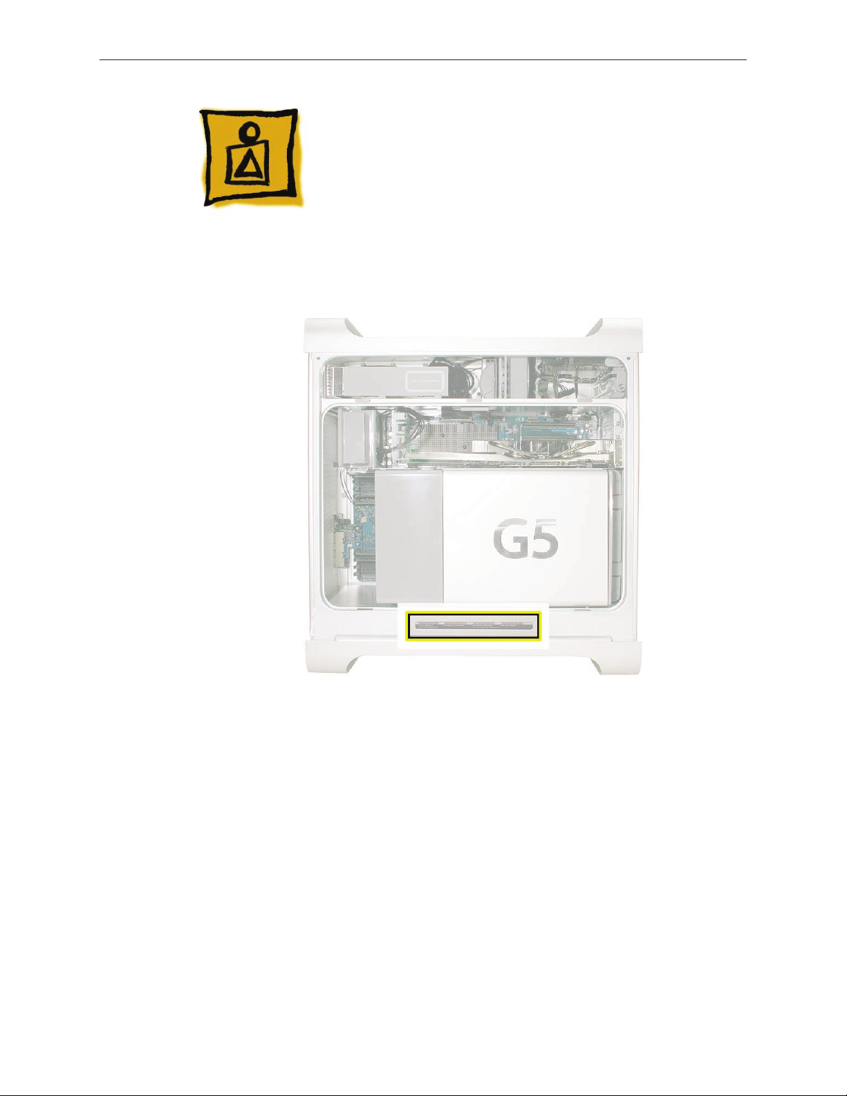
Serial Number Location
To identify a particular Power Mac G5 (Late 2005) computer, check the computer’s serial number,
which lists the model’s conguration. The serial number is located directly below the air deector
inside the side access panel.
Power Mac G5 (Late 2005) Basics 17
Page 18

Liquid Cooling System (LCS)
The Power Mac G5 (Late 2005 Quad) conguration uses a liquid cooling system (LCS) to manage
the temperature in the computer. The liquid cooling system is sealed and is designed to be
opened only by an Apple Authorized Service Provider (AASP). To ensure proper safety and
handling of the LCS system, please read the following information.
General Safety Information
The LCS cooling system uid is predominantly water (80% or greater) with a mixture of corrosion
inhibitors and bacterial growth preventatives. In normal use in a non-leaking LCS there are no
special handling considerations. However, if a leak in the system is suspected or discovered and
the computer is plugged in, remove power to the computer by pulling the power plug.
Nitrile or rubber glove should be worn when handling an LCS module that is leaking or
suspected to be leaking. Evidence of leaks would include corrosion around ttings in the LCS
coolant system, a liquid present, or a slick or slimy feel when handling the part. For leaks or spills,
wipe up the uid using rags, paper towels, or other suitable materials. Dispose of all cleaning
materials according to local laws and regulations Do not combine used coolant with any other
chemical.
When returning a failed LCS module to Apple, place the module (leaking or not) in the packaging
that the replacement module came in. Follow the packaging instructions included with the
replacement module. Failure to follow the instructions could damage the equipment and void
warranty coverage.
Safety Guidelines
Below is a summary of rst aid measures for exposure to the liquid. For complete instructions
refer to the Material Safety Data Sheets (MSDS) for the liquid. The Safety Data Sheets can be
found at http://www.apple.com/environment/resources/msds.html.
Eyes: Immediately ush with plenty of water. If wearing contact lenses, after initial ushing,
remove contact lenses and continue to ush for 15 minutes. Have eyes examined by a
medical professional if irritation persists.
Skin: Wash skin with running water. Remove contaminated clothing. The recommended
ushing is 15 minutes if pain or irritation occurs. Seek medical attention if irritation or
redness develops.
Ingestion: Ingestion of this product, while unlikely to occur in its containment, may cause
irritation of the mouth and throat, gastric upset, stomach ache, cramps, nausea and vomiting.
Power Mac G5 (Late 2005) Basics 18
Page 19

If the product is swallowed, CALL PHYSICIAN OR POISON CONTROL CENTER FOR MOST
CURRENT INFORMATION. If professional advice is not available, do not induce vomiting.
Contaminated individuals should drink milk, egg whites, or large quantities of water. Never
induce vomiting or give diluents (milk or water) to someone who is unconscious, having
convulsions, or unable to swallow.
Power Mac G5 (Late 2005) Basics 19
Page 20

Service Source
Take Apart
Power Mac G5 (Late 2005)
© 2005 Apple Computer, Inc. All rights reserved.
Page 21

General Information
Orientation
For most take-apart procedures, it is recommended that you lay the computer on its side before
removing or installing the part. For proper operation, however, Apple recommends that the
unit be run in the upright position. The computer should never be operated on its side with the
access panel facing down.
Tools
The following tools are required to service all congurations of the computer:
Long-handled magnetic Phillips #1 screwdriver
•
Long-handled 3 mm athead hex screwdriver
•
Long-handled 4 mm ballhead hex screwdriver
•
Long-handled T-10 torx screwdriver
•
9/32-inch nut driver
•
1/4-inch nut driver
•
Short-handled or right-handled magnetic Phillips #2 screwdriver
•
Flatblade screwdriver
•
Jeweler’s atblade screwdriver
•
Jeweler’s Phillips #0 screwdriver
•
Needlenose pliers
•
Small wire cutter
•
Xacto knife
•
Tape (for temporarily holding cables out of the way)
•
Small mirror (for seeing small boards inside the enclosure)
•
Soft cloth (for protecting removed parts from scratches)
•
Special Tools
Three of the tools listed above are available through GSX. The tools and their part numbers are
Long-handled 3 mm athead hex screwdriver (922-7122)
•
Long-handled 4 mm ballhead hex screwdriver (922-7082)
•
Long-handled T-10 torx screwdriver (922-7083)
•
These tools are necessary for removing/installing the processor and logic board in all
congurations.
Power Mac G5 (Late 2005) Take Apart — General Information 21
Page 22
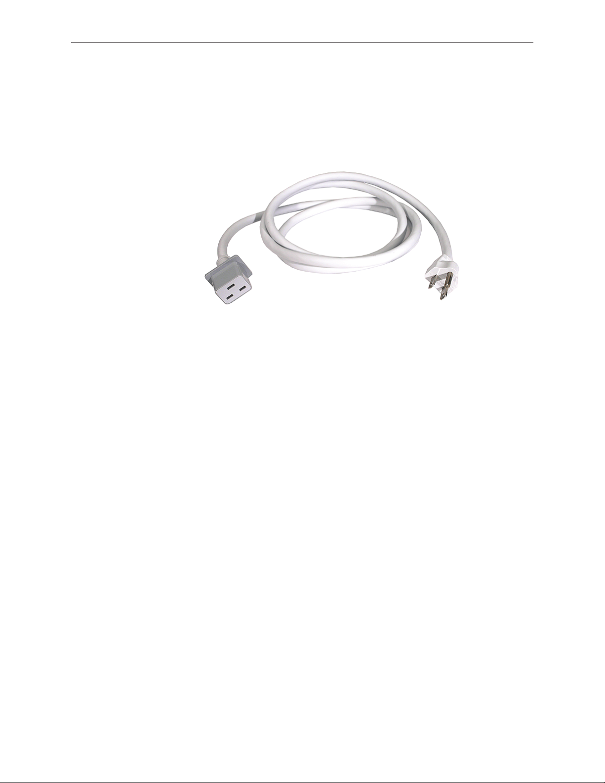
Power Cord
The power cord for the Power Mac G5 (Late 2005) is a heavy-duty cord that is specic to this
model. The Power Mac G5 (Late 2005) power cord accommodates the computer’s more powerful
power supply.
Power cords from earlier Power Mac G5 models are not compatible and will not t the power
cord socket on the back of the Power Mac G5 (Late 2005) computer. Therefore, to supply power
for troubleshooting or testing a Power Mac G5 (Late 2005) computer, you must make sure you
have on hand its specic power cord. You can order the power cord from GSX as part number
922-6782 (in North America). This power cord is compatible with all Power Mac G5 (Late 2005)
congurations.
Parts Requiring Enclosure Replacement
The following are not separate, orderable parts. To replace them, you must replace the enclosure.
Media blower
•
Hard drive locking latches
•
Hard drive bay
•
Optical drive levers
•
Media shelf
•
Media bay sensor
•
Media bay sensor and air deector sensor cable
•
Rear panel latch
•
Take Apart Procedures
This manual covers dierent congurations of the Power Mac G5 (Late 2005) computer. Some
congurations may look slightly dierent from the one shown in the illustrations; however, except
where indicated, the following procedures apply to all congurations.
Power Mac G5 (Late 2005) Take Apart — General Information 22
Page 23

Opening the Computer
Tools
No tools are required for this procedure.
Preliminary Steps
1.
Shut down the computer.
Warning: Always shut down the computer before opening it to avoid damaging its internal
components or the components you are installing. Do not open the computer or attempt to
install items inside it while it is on.
2.
Wait 5 to 10 minutes to allow the computer’s internal components to cool.
Warning: After you shut down the system, the internal components can be very hot. You
must let the computer cool down before continuing.
3.
Unplug all external cables from the computer except the power cord.
4.
Touch the metal PCI access covers on the back of the computer to discharge any static
electricity from your body.
Important: Always discharge static before you touch any parts or install any components
inside the computer. To avoid generating static electricity, do not walk around the room until
you have nished working and closed the computer.
5.
Unplug the power cord.
Warning: To avoid damaging its internal components or the components you want to
install, always unplug the computer before attempting any take-apart procedure.
6.
Put on an ESD wrist strap.
Power Mac G5 (Late 2005) Take Apart — Opening the Computer 23
Page 24

Procedure
Hold the side access panel and lift the latch on the back of the computer.
1.
Warning: The edges of the access panel and the enclosure can be sharp. Be very careful
when handling them.
Remove the access panel and place it on a at surface covered by a soft, clean cloth.
2.
Replacement Note: Make sure the latch is in the up position before replacing the access
panel. If the latch is down, the access panel will not seat correctly in the enclosure.
Power Mac G5 (Late 2005) Take Apart — Opening the Computer 24
Page 25
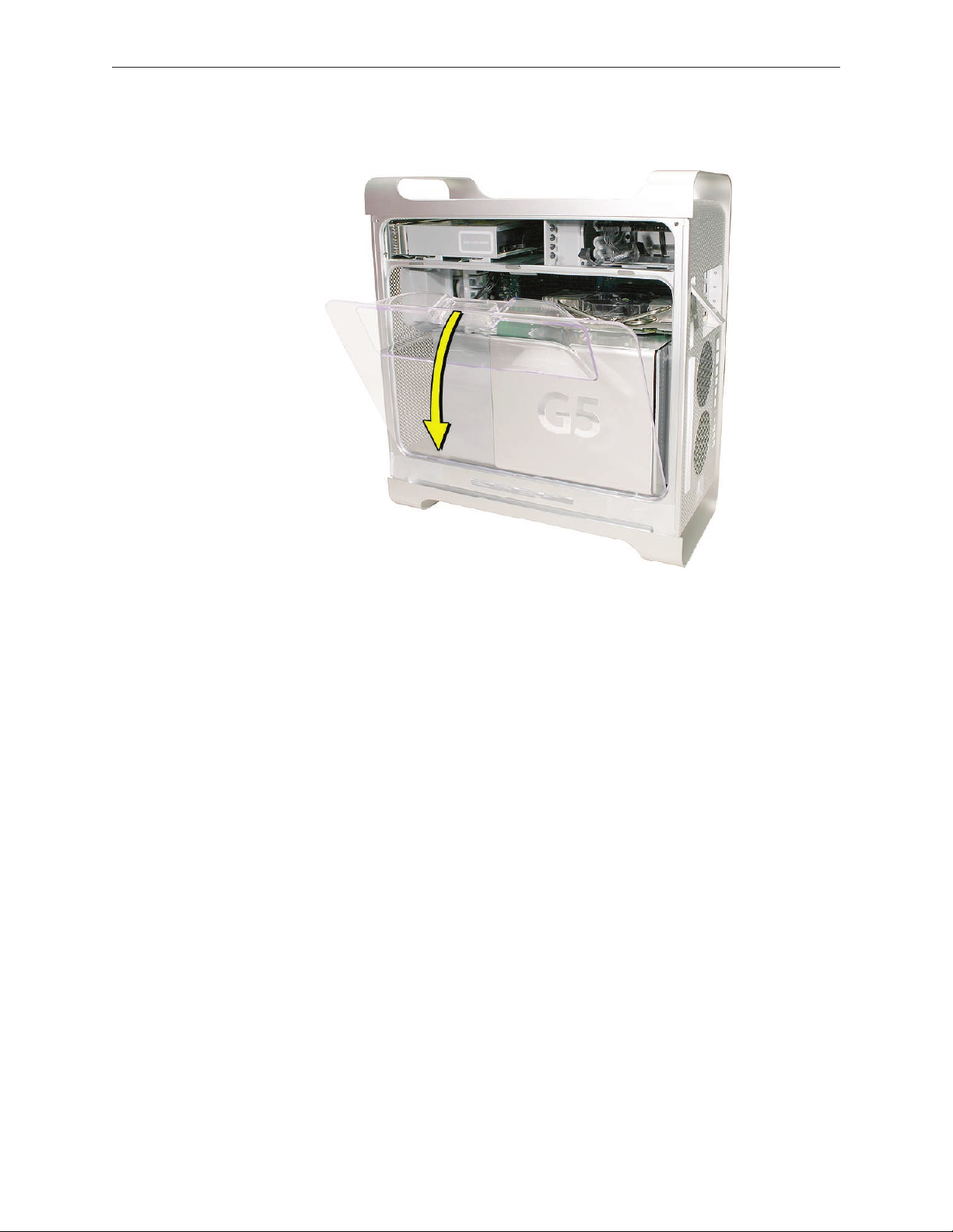
Remove the air deector and place it on a soft, clean cloth.
3.
Replacement Note: To replace the air deector, insert the three tabs on the bottom edge of the
deector into the three slots in the bottom frame of the enclosure. Then swing the deector up
ush against the top frame of the enclosure.
Important: Make sure you re-install the air deector before replacing the access panel. If the air
deector is not installed, the computer will not function properly.
Power Mac G5 (Late 2005) Take Apart — Opening the Computer 25
Page 26
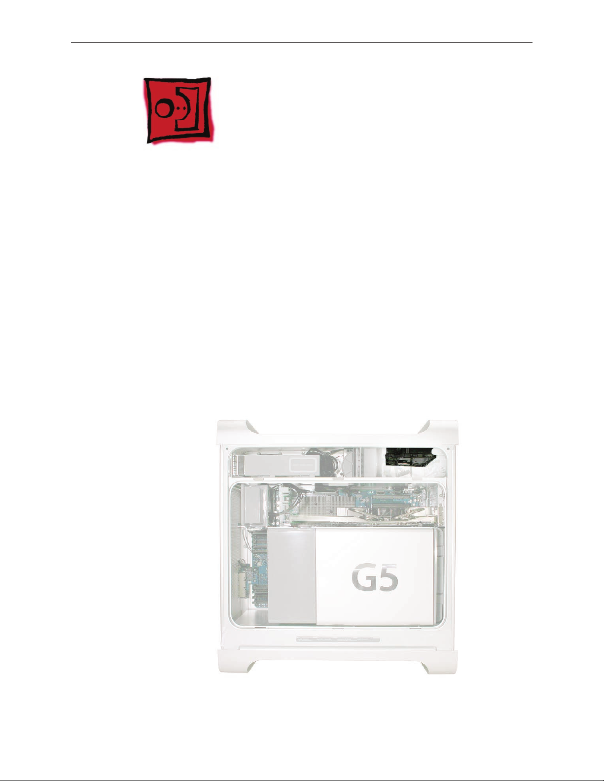
Serial ATA Hard Drive
The Power Mac G5 computer can accommodate two serial ATA hard drives in its internal hard
drive bay. In most congurations, a single hard drive occupies the top portion of the bay. You can
install one additional serial ATA hard drive to the empty slot in the bay.
Important: Use the original Apple cables that came with the Power Mac G5 when installing ATA
hard drives.
Tools
The only tool required for this procedure is a Phillips #1 screwdriver.
Preliminary Steps
Before you begin, open the computer.
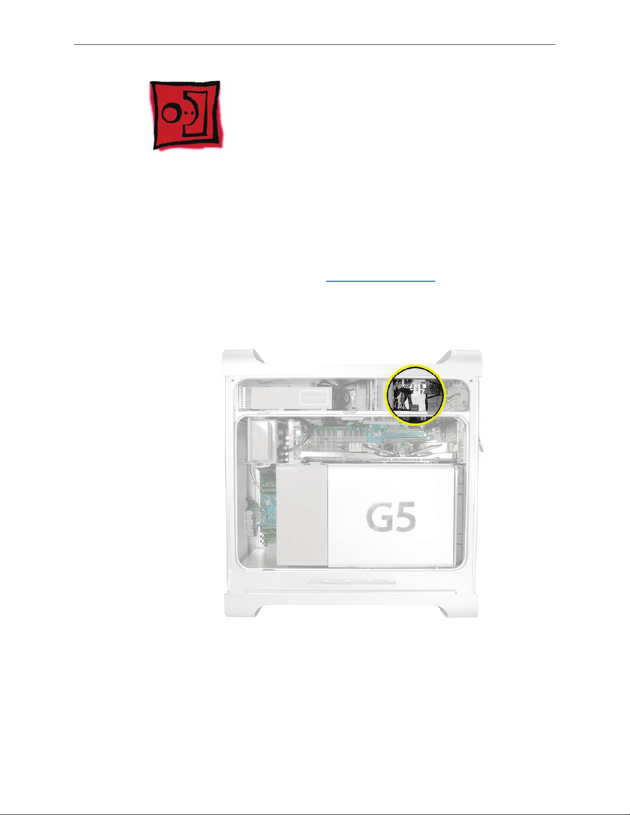
Part Location
Power Mac G5 (Late 2005) Take Apart — Serial ATA Hard Drive 26
Page 27
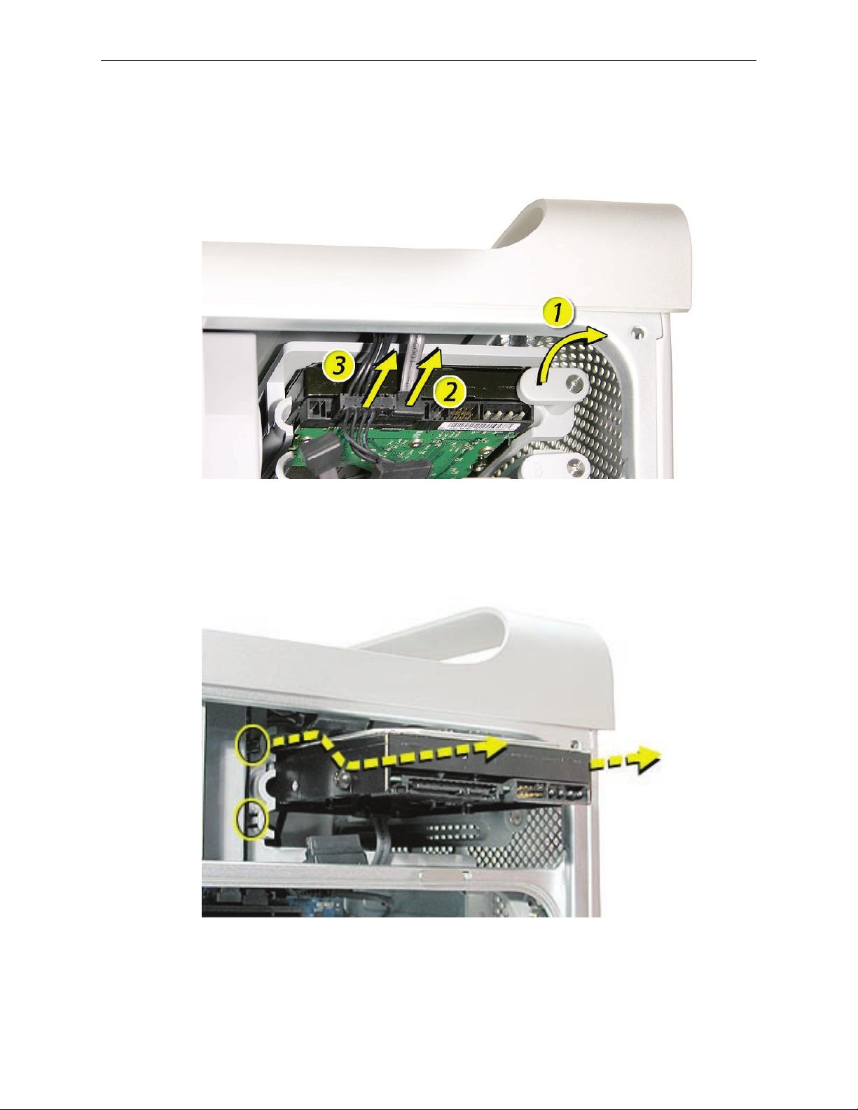
Procedure
Release the drive locking latch by rotating it up.
1.
Disconnect the drive data cable and power cable from the hard drive.
2.
Pull the drive out of the drive bay, being careful not to touch the bottom of the drive.
3.
Note: If you encounter resistance, use a atblade screwdriver to release the latches on the
drive bay rails as you pull the drive out of the bay. (See circled areas on the illustration
below.) If two drives are installed, remove the bottom drive rst.
Important: If the printed circuit board (PCB) is exposed on the bottom of the hard drive,
hold the drive by its sides. To avoid damaging the replacement drive, take care not to touch
the PCB during installation.
Power Mac G5 (Late 2005) Take Apart — Serial ATA Hard Drive 27
Page 28
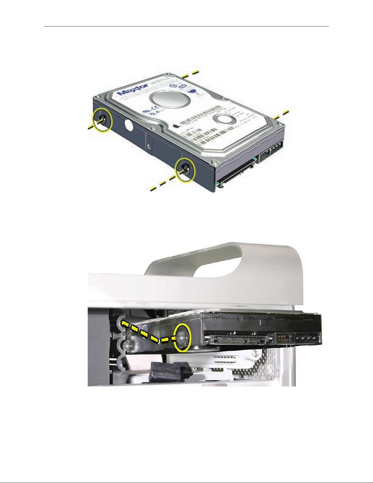
Replacement Note: If you are replacing a hard drive with a new drive, transfer the four guide
screws from the sides of the original drive to the new drive. If you are installing an additional
drive, transfer the guide screws from the side of the hard drive bay to the drive.
Replacement Note: When replacing the top drive, make sure the guide screws align with the
middle slot of the drive bay, and then gently push the drive into the bay until it snaps into place.
When installing a bottom drive, align the guide screws with the bottom slot of the drive bay and
slide the drive in until it snaps into place.
Power Mac G5 (Late 2005) Take Apart — Serial ATA Hard Drive 28
Page 29
Serial ATA Hard Drive Data Cable
Tools
The only tool required for this procedure is a small wire cutter.
Preliminary Steps
Before you begin, open the computer and remove the hard drive(s).
Part Location
Power Mac G5 (Late 2005) Take Apart — Serial ATA Hard Drive Data Cable 29
Page 30
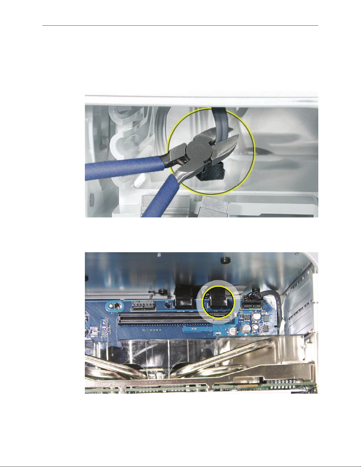
Procedure
Upper Hard Drive Cable
Clip o the connector from the hard drive end of the upper hard drive data cable.
1.
Disconnect the cable from the logic board, pull the cable out of the hard drive bay, and
2.
remove the cable from the enclosure.
Power Mac G5 (Late 2005) Take Apart — Serial ATA Hard Drive Data Cable 30
Page 31

Replacement Note: When installing the replacement upper hard drive cable, rst route the cable
through the opening in the hard drive bay.
Then install the upper hard drive with the cable routed below the drive, and connect the cable to
the drive as illustrated.
Power Mac G5 (Late 2005) Take Apart — Serial ATA Hard Drive Data Cable 31
Page 32

Lower Hard Drive Cable
Clip o the connector from the hard drive end of the lower hard drive cable.
1.
Disconnect the cable from the logic board, pull the cable out of the hard drive bay, and
2.
remove the cable from the enclosure.
Power Mac G5 (Late 2005) Take Apart — Serial ATA Hard Drive Data Cable 32
Page 33

Replacement Note: When installing the replacement lower hard drive cable, rst route the cable
through the opening in the hard drive bay.
Then install the lower hard drive with the cable routed above the drive, and connect the cable to
the drive as illustrated.
Power Mac G5 (Late 2005) Take Apart — Serial ATA Hard Drive Data Cable 33
Page 34

Optical Drive
Important: When installing a replacement optical drive, use the original Apple cables that came
with the Power Mac G5.
Tools
No tools are required for this procedure.
Preliminary Steps
Before you begin, open the computer.
Part Location
Power Mac G5 (Late 2005) Take Apart — Optical Drive 34
Page 35

Procedure
Disconnect the optical drive ribbon cable from the logic board. (The cable connector is
1.
located under the media shelf that holds the optical drive.)
Push the optical drive levers out to release the drive.
2.
Power Mac G5 (Late 2005) Take Apart — Optical Drive 35
Page 36

Place the ngers on one hand inside the opening for the optical drive cable. Push the edge
3.
of the drive forward and then up. The drive will move part way out of the media shelf.
Disconnect the power cable from the drive.
4.
Route the drive ribbon cable out through the opening in the media shelf and remove the
5.
drive and ribbon cable from the computer.
Power Mac G5 (Late 2005) Take Apart — Optical Drive 36
Page 37

If you are replacing the drive with a new drive, do the following:
6.
• Disconnect the ribbon cable from the back of the drive, and then carefully pry the cable
from the top of the drive. Transfer the cable to the top of the replacement drive, and
connect the cable to the drive.
Note: Reusable adhesive tape on the underside of the cable attaches the cable to the
drive. When removing the cable from the original drive, be careful to keep the tape with
the cable.
• Carefully remove the EMI shield from the front of the original drive and transfer it to the
front of the replacement drive.
Replacement Note: Insert the optical drive part way into the optical drive bay, and connect the
power cable to the drive. Then bend down the free end of the ribbon cable, route it through the
opening at the back of the media shelf, and connect the cable to the logic board.
Power Mac G5 (Late 2005) Take Apart — Optical Drive 37
Page 38

Front Inlet Fan Assembly
Tools
No tools are required for this procedure.
Preliminary Steps
Before you begin, open the computer and lay it on its side with the access side facing up.
Part Location
Power Mac G5 (Late 2005) Take Apart — Front Inlet Fan Assembly 38
Page 39

Procedure
Hold the front inlet fan assembly by the front handle and rmly pull it out of the computer. 1.
Power Mac G5 (Late 2005) Take Apart — Front Inlet Fan Assembly 39
Page 40

Replacement Note: To replace the front inlet fan bracket in the enclosure, align the large rail on
the bracket with the cutout in the PCI divider and press rmly.
Important: Make sure the connector on the fan fully engages the fan connector on the logic
board, or the computer will not operate properly. Gently pull the fan assembly to test whether it
is connected.
Power Mac G5 (Late 2005) Take Apart — Front Inlet Fan Assembly 40
Page 41

Memory (DIMMs)
The SDRAM DIMMs must be installed
in pairs with one DIMM per bank.
DIMMs are already installed in these two slots.
Install additional
DIMMs in these
two slots first.
If slots are available, and you want to
install more memory, install additional DIMMs in a
similar fashion: In pairs, one per bank, from the center outward.
Bank 1 Bank 2
The Power Mac G5 (Late 2005) has eight DIMM slots for PC2 4200, 533 MHz, Double-Data-Rate
2 (DDR2) SDRAM DIMMs. The slots are arranged in two banks of four slots each. Power Mac G5
(Late 2005) computers come with a minimum of 512 MB of RAM, installed as a pair of 256 MB
DIMMs in the two center slots. Additional DIMMs can be installed in the open DIMM slots, as
illustrated below.
Note: DIMMs must be installed in equal-sized pairs from the center outward.
Power Mac G5 (Late 2005) Take Apart — Memory (DIMMs) 41
Page 42

In the Power Mac G5 (Late 2005), DIMMs must t these specications:
PC2 4200, 533 MHz, DDR2 DIMMs
•
240-pin module
•
Maximum number of memory devices on DDR2 SDRAM: 18
•
Nonparity
•
Unbuered (registered or buered DDR2 SDRAM cannot be used)
•
Either error-correcting code (ECC) or no error-correcting code (NECC) modules
•
Note: Do not mix ECC and NECC memory modules within a pair. (See the “General
Information” section of Troubleshooting for information on identifying ECC and NECC
DIMMs.)
Important: Memory from older Macintosh computers is not compatible with the Power Mac G5
(Late 2005).
Tools
No tools are required for this procedure.
Preliminary Steps
Before you begin, open the computer, lay it on its side with the access side facing up, and
remove the front inlet fan assembly.
Part Location
Power Mac G5 (Late 2005) Take Apart — Memory (DIMMs) 42
Page 43

Procedure
Locate the DIMM slots on the logic board.
1.
Open the ejectors on the DIMM slot by pushing them out to the sides.
2.
Holding the DIMM by both top corners, lift it straight up out of the computer.
3.
Replacement Note: Align the DIMM in the slot and push both ends of the DIMM down until the
tabs are vertical and the ejectors snap into place.
Important: Do not touch the DIMM connectors. Handle the DIMM only by the edges.
Power Mac G5 (Late 2005) Take Apart — Memory (DIMMs) 43
Page 44
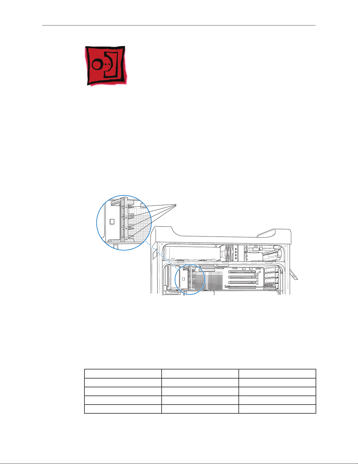
Graphics Card/PCI Express
The maximum bus width for each PCI Express slot is
marked on the card guide. Slot 4 is a 4-lane (4x) slot,
slot 3 is an 8-lane (8x) slot, slot 2 is a 4-lane (4x) slot,
and slot 1 is a 16-lane (16x) slot.
Card
Power Mac G5 (Late 2005) computers have four expansion card slots that accommodate PCI
Express cards. The computers come with a high-performance 16-lane (16x) PCI Express graphics
card installed in slot 1. The card contains the graphics processor unit (GPU) and provides the
computers’ display ports.
You can install additional PCI Express cards in slots 2–4. Install a second card in slot 3, a third in
slot 4, and a fourth in slot 2 to take advantage of the bus bandwidth of each slot. Before installing
a card, check the specications to make sure it can operate in the Power Mac G5 (Late 2005).
Note: When certain high-end video cards are installed in slot 1, they block the adjacent PCI
Express slot (slot 2). As a result, you can install PCI Express cards in slots 3 and 4 but not in slot 2.
Important: Combined maximum power consumption for all four expansion slots should not
exceed 200 W. Combined maximum video RAM for all graphics cards is 1 GB.
While all slots can accommodate PCI Express cards that have up to 16-lanes, if you install a card
that requires a greater bandwidth than the slot provides, the card will operate at the bandwidth
of the slot. For example, an 8x card installed in a 4x slot will operate as a 4x card. Refer to the
following table for details.
PCI Express Slot Bus Bandwith (x) Connector (Lane)
4 4x 16 lane
3 8x 16 lane
2 4x 16 lane
1 16x 16 lane
Power Mac G5 (Late 2005) Take Apart — Graphics Card/PCI Express Card 44
Page 45

Tools
The only tool required for this procedure is a Phillips #1 screwdriver.
Preliminary Steps
Before you begin, open the computer and lay it on its side with the access side facing up.
Part Location
Procedure for All Cards Except NVIDIA Quadro FX 4500
Install video cards in slot 1 only. Install other PCI Express cards in the slots labeled 2, 3, and 4.
Warning: When removing or installing a card, handle it only by the edges. Do not touch its
connectors or any of the components on the card. Lift the card straight out from the connector
to remove it, and insert it straight into the connector to install it. Do not rock the card from side
to side and don’t force the card into the slot. Once the replacement card is installed, pull on it
gently to check that it is properly connected.
Power Mac G5 (Late 2005) Take Apart — Graphics Card/PCI Express Card 45
Page 46

Remove the screw that mounts the card to the enclosure.
1.
If you are removing a video card, pull back the small locking clip at the front of the
2.
connector.
Holding the card by the top corners, gently pull up the card and remove it from its
3.
expansion slot.
Replacement Note: Align the card’s connector with the expansion slot and press until the
connector is inserted all the way into the slot. If you’re installing a 12-inch card, make sure the
card engages the appropriate slot in the PCI card guide.
Don’t rock the card from side to side; instead, press the card straight into the slot.
•
Don’t force the card. If you meet a lot of resistance, pull the card out. Check the connector
•
and the slot for damage or obstructions, then try inserting the card again.
Pull the card gently to see if it is properly connected. If it resists and stays in place, and if its
•
gold connectors are barely visible, the card is connected.
Power Mac G5 (Late 2005) Take Apart — Graphics Card/PCI Express Card 46
Page 47

Procedure for NVIDIA Quadro FX 4500 Card and Cable
To remove the Quadro FX 4500 card, do the following:
Remove the two screws that mount the card to the enclosure.
1.
Disconnect the Quadro FX 4500 cable from the card.
2.
Holding the card by the top corners, gently pull up the card and remove it from its
3.
expansion slot.
Replacement Note: When replacing the Quadro FX 4500 card, position the card over the slot
by carefully aligning the end of the card in the rst slot in the PCI card guide and the two screw
holes in the card fence with the rst two PCI card screw holes in the enclosure. Then press down.
Power Mac G5 (Late 2005) Take Apart — Graphics Card/PCI Express Card 47
Page 48

To remove the Quadro FX 4500 cable, do the following:
Remove the Quadro FX 4500 card from the enclosure (refer to preceding steps).
1.
Locate the PCI card guide.
2.
Remove the two screws that mount the PCI card guide to the logic board.
3.
Slide the card guide up to release the two latches from the PCI divider, and remove the card
4.
guide from the enclosure.
Power Mac G5 (Late 2005) Take Apart — Graphics Card/PCI Express Card 48
Page 49

Disconnect the Quadro FX 4500 cable from the logic board and remove the cable from the
5.
enclosure.
Power Mac G5 (Late 2005) Take Apart — Graphics Card/PCI Express Card 49
Page 50

Battery
Tools
No tools are required for this procedure. You may, however, nd a at-blade screwdriver useful in
removing the battery from its holder.
Preliminary Steps
Before you begin, open the computer, lay it on its side with the access side facing up, and
remove the front inlet fan assembly. If a memory DIMM is installed in the slot next to the
battery, remove the DIMM.
Part Location
Power Mac G5 (Late 2005) Take Apart — Battery 50
Page 51

Procedure
If necessary, carefully spread the two tabs holding the battery.
1.
Remove the battery from its holder.
2.
Replacement Note: Insert the new battery in the holder, making sure the battery’s negative
symbol (–) faces up.
Warning: Installing the battery incorrectly may cause an explosion. Be sure the battery’s positive
and negative sides are correctly oriented in the holder. Use only the same type of battery or an
equivalent recommended by the manufacturer of the original.
Important: Batteries contain chemicals, some of which may be harmful to the environment.
Please dispose of used batteries according to your local environmental laws and guidelines.
Power Mac G5 (Late 2005) Take Apart — Battery 51
Page 52

AirPort Extreme/Bluetooth Combo Card and Runway Card
Note: The combo card is connected to an adapter card called the runway card. This procedure
includes steps for removing both the combo and runway cards. However, if you are replacing just
the combo card, it is not necessary to remove the runway card from the enclosure.
Tools
The only tools required for this procedure are a jeweler’s Phillips #0 screwdriver and Xacto knife.
Preliminary Steps
Before you begin, open the computer, lay it on its side with the access side facing up, and
remove the front inlet fan assembly. If a memory DIMM is installed in the slot next to the
combo card, remove the DIMM.
Part Location
Power Mac G5 (Late 2005) Take Apart — AirPort Extreme/Bluetooth Combo Card 52
Page 53

Procedure
Using a jeweler’s Phillips screwdriver, remove the two combo card mounting screws.
1.
Disconnect the combo card antennas from the clip on the side of the PCI divider.
2.
Disconnect the combo card from the runway card and lift up a short distance.
3.
Disconnect the two antenna cables from the card and remove the card from the enclosure.
4.
Replacement Note: The cables can attach to either connector on the card.
Power Mac G5 (Late 2005) Take Apart — AirPort Extreme/Bluetooth Combo Card 53
Page 54

To remove the runway card (after removing the combo card), do the following:
Note: The runway card is attached to the PCI divider by two black rivets. You must remove the
rivets before disconnecting the card from the logic board.
Using a Xacto knife, pry up and remove the center plug of the rst black rivet. Then pry up
1.
and remove the outer casing for the rivet.
Repeat for the second rivet.
2.
Holding the runway card by its top edge, pull straight up to disconnect the card from the
3.
logic board.
Power Mac G5 (Late 2005) Take Apart — AirPort Extreme/Bluetooth Combo Card 54
Page 55

PCI Card Guide
Tools
The only tool required for this procedure is a Phillips #1 screwdriver.
Preliminary Steps
Before you begin, open the computer, lay it on its side with the access side facing up, and
remove any 12-inch graphics or PCI Express cards.
Part Location
Power Mac G5 (Late 2005) Take Apart — PCI Card Guide 55
Page 56

Procedure
Remove the two screws that mount the PCI card guide to the logic board.
1.
Slide the card guide up to release the two latches from the PCI divider, and remove the card
2.
guide from the enclosure.
Power Mac G5 (Late 2005) Take Apart — PCI Card Guide 56
Page 57

Speaker/Fan Assembly
Tools
No tools are required for this procedure.
Preliminary Steps
Before you begin, open the computer, lay it on its side with the access side facing up, and remove
the following:
Any 12-inch graphics or PCI Express cards
•
PCI card guide.
•
Part Location
Power Mac G5 (Late 2005) Take Apart — Speaker/Fan Assembly 57
Page 58

Procedure
Disconnect the speaker and fan cables from the logic board.
1.
Lift the speaker/fan assembly straight up and remove it from the enclosure.
2.
Important: Be careful that the fan and speaker cables do not catch on the PCI divider as you
lift the assembly.
Replacement Note: When reinstalling the speaker/fan bracket in the enclosure, make sure the
large tab on the side of bracket engages with the channel in the PCI divider.
Power Mac G5 (Late 2005) Take Apart — Speaker/Fan Assembly 58
Page 59

Ambient Board
Tools
No tools are required for this procedure.
Preliminary Steps
Before you begin, open the computer, lay it on its side with the access side facing up, and remove
the following:
Any 12-inch graphics or PCI Express cards
•
PCI card guide
•
Speaker/fan assembly
•
Part Location
Power Mac G5 (Late 2005) Take Apart — Ambient Board 59
Page 60

Procedure
Locate the ambient board connected to the logic board.
1.
Position your ngers on both sides of the board. Gently rock the board from side-to-side,
2.
pulling it straight up and out of the connector.
Power Mac G5 (Late 2005) Take Apart — Ambient Board 60
Page 61

Heatsink Cover
Warning: If you are not certied to service this product, removing the heatsink cover will void
the computer’s warranty.
Tools
The only tool required for this procedure is a Xacto knife.
Preliminary Steps
Before you begin, open the computer, lay it on its side with the access side facing up, and
remove the front inlet fan assembly.
Part Location
Power Mac G5 (Late 2005) Take Apart — Heatsink Cover 61
Page 62

Procedure
Locate the locking rivet that secures the processor heatsink cover to the PCI divider.
1.
Using a Xacto knife, pry up and remove the plug at the center of the locking rivet.
2.
Pry up and remove the outer casing for the rivet.
3.
Replacement Note: For Power Mac G5 (Late 2005 Dual) computers, you do not need to
replace the rivet after you have replaced the heatsink cover. For Power Mac G5 (Late 2005
Quad), you must replace the rivet. Extra rivets are available as part number 922-6503.
Power Mac G5 (Late 2005) Take Apart — Heatsink Cover 62
Page 63

Slide the cover to the left to unlatch the four metal latches under the cover. Then lift the
4.
cover up and o the heatsink.
Replacement Note: Place the notches in the underside of the cover directly over the four
mounting pegs. Slide the cover toward the back of the computer and then press down rmly
until you feel the cover lock into place.
Power Mac G5 (Late 2005) Take Apart — Heatsink Cover 63
Page 64

Rear Exhaust Fan Assembly
Tools
The only tools required for this procedure are a Phillips #1 screwdriver and a atblade
screwdriver. If you are replacing the rear exhaust fans with new fans, you will also need
needlenose pliers.
Preliminary Steps
Before you begin, open the computer, lay it on its side with the access side facing up, and remove
the following:
Front inlet fan assembly
•
All graphics and PCI Express cards
•
Heatsink cover
•
Part Location
Power Mac G5 (Late 2005) Take Apart — Rear Exhaust Fan Assembly 64
Page 65

Procedure
Disconnect the fan cable from the logic board.
1.
Note: Press the cable connector up toward the media shelf when disconnecting the cable.
Press down on the two tabs on the top of the fan bracket to release the two latches.
2.
Lift the fan bracket and fans out of the enclosure.
3.
If you are replacing the fans on a Power Mac G5 (Late 2005 Quad) computer, use needlenose
4.
pliers to pull each fan o the four grommets that mount it to the bracket, and remove the
fans and cable from the bracket. Then install the replacement fans in the bracket, using the
grommets included with the fans.
Power Mac G5 (Late 2005) Take Apart — Rear Exhaust Fan Assembly 65
Page 66

Replacement Note: When reinstalling the fan bracket in the enclosure, make sure the two tabs
on the bottom of the bracket engage with the slots in the enclosure’s fan guide.
Then rotate the fan back ush with the rear panel, making sure the two latches on the top of the
bracket engage with the two slots on the top of the fan guide.
Power Mac G5 (Late 2005) Take Apart — Rear Exhaust Fan Assembly 66
Page 67

Replacement Note: Using a atblade screwdriver, tuck the fan cable under the edge of the logic
board.
Power Mac G5 (Late 2005) Take Apart — Rear Exhaust Fan Assembly 67
Page 68

PCI Divider
Tools
The only tools required for this procedure are a Phillips #1 screwdriver and Xacto knife.
Preliminary Steps
Before you begin, open the computer, lay it on its side with the access side facing up, and remove
the following:
Front inlet fan assembly
•
All graphics and PCI Express cards
•
PCI card guide
•
Speaker/fan assembly
•
Heatsink cover
•
Part Location
Power Mac G5 (Late 2005) Take Apart — PCI Divider 68
Page 69

Procedure
Note: The combo card’s runway card is attached to the PCI divider by two black rivets. Before you
can remove the card from the PCI divider, you must remove both rivets and disconnect the card
from the logic board. You do not, however, have to remove the runway card or combo card from
the enclosure.
Using a Xacto knife, pry up and remove the center of the rst black rivet that mounts the
1.
runway card to the PCI divider.
Pry up and remove the outer casing for the rivet.
2.
Repeat steps 1 and 2 for the second rivet.
3.
Power Mac G5 (Late 2005) Take Apart — PCI Divider 69
Page 70

Remove the combo card antenna cables from the clip on the side of the PCI divider.
4.
Holding the runway card by its top edge, pull straight up to disconnect the card from the
5.
logic board.
Set the runway card (with combo card attached) to the side. (There is no need to remove the
6.
runway card from the enclosure.)
Power Mac G5 (Late 2005) Take Apart — PCI Divider 70
Page 71

Remove the processor heatsink cable from the clip on the PCI divider.
7.
Remove the three black PCI divider mounting screws.
8.
Lift the PCI divider out of the enclosure.
9.
Replacement Note: Align the PCI divider on the logic board by placing it over the runway card
connector. Be sure to replace the processor heatsink cable in the clip on the PCI divider.
Power Mac G5 (Late 2005) Take Apart — PCI Divider 71
Page 72

Media Bay Fan
Tools
The only tool required for this procedure is a short-handled or right-angle Phillips #2 screwdriver.
Preliminary Steps
Before you begin, open the computer, lay it on its side with the access side facing up, and remove
the following:
Front inlet fan assembly
•
All graphics and PCI Express cards
•
PCI card guide
•
Speaker/fan assembly
•
Heatsink cover
•
PCI divider
•
Part Location
Power Mac G5 (Late 2005) Take Apart — Media Bay Fan 72
Page 73

Procedure
Disconnect the media bay fan cable from the logic board.
1.
Remove the two media bay fan mounting screws.
2.
Rotate the fan counterclockwise.
3.
Route the fan cable out through the opening in the media bay shelf and remove the fan
4.
from the media bay.
Power Mac G5 (Late 2005) Take Apart — Media Bay Fan 73
Page 74

Replacement Note: After placing the fan in the media bay, make sure the tabs on the bottom
of the fan engage with the slots in the media bay shelf. Then rotate the fan clockwise back into
position.
Power Mac G5 (Late 2005) Take Apart — Media Bay Fan 74
Page 75

Processor Inlet Frame (Dual 2.0/2.3 GHz)
Tools
No tools are required for this procedure.
Preliminary Steps
Before you begin, open the computer, lay it on its side with the access side facing up, and remove
the following:
•
Front inlet fan assembly
•
Heatsink cover
Part Location
Power Mac G5 (Late 2005) Take Apart — Processor Inlet Frame (Dual 2.0/2.3 GHz) 75
Page 76

Procedure
Lift the processor inlet frame o the processor.
1.
Remove the frame from the enclosure.
2.
Replacement Note: If you are replacing the processor inlet frame with a new inlet frame on the
Power Mac G5 (Late 2005 Dual 2.0 GHz/Dual 2.3 GHz) computer, check the replacement parts box
for an enclosed label. Before installing the frame, apply the label to the frame as illustrated below.
Power Mac G5 (Late 2005) Take Apart — Processor Inlet Frame (Dual 2.0/2.3 GHz) 76
Page 77

Processor (Dual 2.0/2.3 GHz)
Tools
The only tools required for this procedure are a long-handled 3 mm athead hex driver and a
long-handled 4 mm ballhead hex driver.
Preliminary Steps
Before you begin, open the computer, lay it on its side with the access side facing up, and remove
the following:
Front inlet fan assembly
•
All graphics and PCI Express cards
•
Rear exhaust fan assembly
•
Heatsink cover
•
Processor inlet frame (Dual 2.0/2.3 GHz)
•
Part Location
Power Mac G5 (Late 2005) Take Apart — Processor (Dual 2.0/2.3 GHz) 77
Page 78

Procedure
Using a long-handled 3 mm athead hex driver, remove the six processor mounting screws.
1.
(Four long screws mount the upper platform and two short screws mount the power supply
terminal on the level below.)
Insert a long-handled 4 mm ballhead hex driver into the two holes on the top of the
2.
heatsink and loosen (but do not remove) the two captive screws.
Power Mac G5 (Late 2005) Take Apart — Processor (Dual 2.0/2.3 GHz) 78
Page 79

Holding the processor/heatsink by the bottom metal platform, lift the assembly straight up
3.
out of the enclosure.
Warning: The heatsink and processor are one unit. Do not attempt to separate the heatsink from
the processor.
Power Mac G5 (Late 2005) Take Apart — Processor (Dual 2.0/2.3 GHz) 79
Page 80

Replacement Procedure
If you are replacing the processor with a new processor, do the following:
1.
• When removing the new processor from its packaging, be careful to lift the processor
straight up out of the box. Tilting the processor could damage the heatsink seal.
• Before installing the processor, remove the cap over the processor connector.
Lower the processor over the processor standos, and press down on the metal platform to
2.
make sure the processor is connected to the logic board. Gently rock the heatsink until it
feels seated.
Warning: Don’t press on the top of the heatsink or you’ll damage the processor.
Power Mac G5 (Late 2005) Take Apart — Processor (Dual 2.0/2.3 GHz) 80
Page 81

Note: For steps 3–6, remove or loosen the screws in the order indicated in the illustrations.
Insert a long-handled 4 mm ballhead hex driver into the two holes on the top of the
3.
heatsink and tighten the two captive screws.
Using a long-handled 3 mm athead hex driver, replace the two short screws that mount the
4.
power supply terminal.
Power Mac G5 (Late 2005) Take Apart — Processor (Dual 2.0/2.3 GHz) 81
Page 82

Using a long-handled 3 mm athead hex driver, replace the four long processor mounting
5.
screws.
Replace the processor inlet frame on the front of the heatsink.
6.
Replace the heatsink cover.
7.
Replace the rear exhaust fan assembly.
8.
Replace all graphics and PCI Express cards.
9.
Replace the front inlet fan assembly.
10.
Important: Whenever you replace a processor with a new processor, you must run Apple Service
Diagnostic (once the computer is reassembled). Apple Service Diagnostic for Power Mac G5
(Late 2005) is available as a download from the Disc Images section of the Apple Service Source
website. For more information, see “Thermal Calibration” in the Troubleshooting chapter.
Power Mac G5 (Late 2005) Take Apart — Processor (Dual 2.0/2.3 GHz) 82
Page 83

Processor Inlet Frame (Quad)
Tools
No tools are required for this procedure.
Preliminary Steps
Before you begin, open the computer, lay it on its side with the access side facing up, and remove
the following:
Front inlet fan assembly
•
Heatsink cover
•
Part Location
Power Mac G5 (Late 2005) Take Apart — Processor Inlet Frame (Quad) 83
Page 84

Procedure
Lift the processor inlet frame o the processor.
1.
Remove the frame from the enclosure.
2.
Power Mac G5 (Late 2005) Take Apart — Processor Inlet Frame (Quad) 84
Page 85

Processor (Quad)
Note: There are two versions of the Quad processor. While your processor may look dierent from
the one in the photos, the take-apart steps for both versions are similar. Any dierences are called
out in the procedure that follows.
Tools
The only tools required for this procedure are a long-handled 3 mm athead hex driver and a
long-handled 4 mm ballhead hex driver.
Preliminary Steps
Before you begin, open the computer, lay it on its side with the access side facing up, and remove
the following:
•
Front inlet fan assembly
•
Heatsink cover
•
Processor inlet frame (Quad)
Part Location
Power Mac G5 (Late 2005) Take Apart — Processor (Quad) 85
Page 86

Procedure
Remove the processor support bar cable from the clip on the PCI divider.
1.
Disconnect the processor support bar cable from the processor cable.
2.
Power Mac G5 (Late 2005) Take Apart — Processor (Quad) 86
Page 87

Version 1 Processor
Note: For steps 3–6, remove or loosen the screws in the order indicated in the illustrations.
For Version 2 of the processor, see steps 8-12.
Using a 3 mm athead hex driver, loosen the four captive oat plate screws. (Do not remove
3.
the captive screws from their standos.)
Using a 3 mm athead hex driver, remove the six long processor mounting screws.
4.
Power Mac G5 (Late 2005) Take Apart — Processor (Quad) 87
Page 88

Using a 3 mm athead hex driver, remove the four short screws that mount the two
5.
processor terminal assemblies.
Using a 4 mm ballhead hex driver, loosen the four captive screws near the middle of the
6.
processor.
Power Mac G5 (Late 2005) Take Apart — Processor (Quad) 88
Page 89

Hold the heatsink by the middle and lift the processor/heatsink straight up out of the
7.
computer.
Warning: The heatsink and processor are one unit. Do not attempt to separate the heatsink
from the processor.
Power Mac G5 (Late 2005) Take Apart — Processor (Quad) 89
Page 90

Version 2 Processor
Note: For steps 8-11, remove or loosen the screws in the order indicated in the illustrations.
For Version 1 of the processor, see steps 3-7.
Using a 3 mm athead hex driver, loosen the four captive oat plate screws. (Do not remove
8.
the captive screws from their standos.)
Using a 3 mm athead hex driver, remove the six long processor mounting screws.
9.
Power Mac G5 (Late 2005) Take Apart — Processor (Quad) 90
Page 91

Using a 3 mm athead hex driver, remove the four short screws that mount the two
10.
processor terminal assemblies.
Using a 4 mm ballhead hex driver, loosen the four captive screws near the middle of the
11.
processor.
Power Mac G5 (Late 2005) Take Apart — Processor (Quad) 91
Page 92

Hold the heatsink by the middle and lift the processor/heatsink straight up out of the
12.
computer.
Warning: The heatsink and processor are one unit. Do not attempt to separate the heatsink
from the processor.
Power Mac G5 (Late 2005) Take Apart — Processor (Quad) 92
Page 93

Replacement Procedure
Version 1 Processor
Note: For replacement procedures for Version 2 of the processor, see steps 13-24.
If you are replacing the processor with a new processor, do the following:
1.
• When removing the new processor from its packaging, be careful to lift the processor
straight up out of the box. Tilting the processor could damage the heatsink seal.
• Before installing the processor, remove the caps over the processor connectors.
• Loosen the screws in the order marked below.
Power Mac G5 (Late 2005) Take Apart — Processor (Quad) 93
Page 94

• Check to make sure the top edges of both processors align.
Lower the processor over the processor standos.
2.
Press down on the middle (bridge) of the heatsink to make sure the processor is connected
3.
to the logic board. Gently rock the heatsink until it feels seated.
Warning: Don’t press on the end of the heatsink or you’ll damage the processor.
Power Mac G5 (Late 2005) Take Apart — Processor (Quad) 94
Page 95

Note: For steps 4–7, replace or tighten the screws in the order indicated in the illustrations.
Using a 4 mm ballhead hex driver, tighten the four captive screws near the middle of the
4.
processor.
Using a 3 mm athead hex driver, replace the four short screws that mount the two
5.
processor terminal assemblies.
Power Mac G5 (Late 2005) Take Apart — Processor (Quad) 95
Page 96

Using a 3 mm athead hex driver, replace the six long processor mounting screws.
6.
Using a 3 mm athead hex driver, tighten the four captive oat plate screws.
7.
Power Mac G5 (Late 2005) Take Apart — Processor (Quad) 96
Page 97

8.
Reconnect the processor support bar cable with the processor cable.
9.
Replace the processor support bar cable in the clip on the PCI divider.
10.
Replace the processor inlet frame assembly on the front of the heatsink.
Important: If you are replacing the processor with a new processor, be sure to use the inlet
frame included with the replacement processor.
11.
Replace the heatsink cover.
12.
Replace the front inlet fan assembly.
Important: Whenever you replace a processor with a new processor, you must run Apple
Service Diagnostic (once the computer is reassembled). Apple Service Diagnostic for
Power Mac G5 (Late 2005) is available as a download from the Disc Images section of
the Apple Service Source website. For more information, see “Thermal Calibration” in the
Troubleshooting chapter.
Power Mac G5 (Late 2005) Take Apart — Processor (Quad) 97
Page 98

Version 2 Processor
Note: For replacement procedures for Version 1 of the processor, see steps 1-12
If you are replacing the processor with a new processor, do the following:
13.
• When removing the new processor from its packaging, be careful to lift the processor
straight up out of the box. Tilting the processor could damage the heatsink seal.
• Before installing the processor, remove the caps over the processor connectors.
• Loosen the screws in the order marked below.
Power Mac G5 (Late 2005) Take Apart — Processor (Quad) 98
Page 99

• Check to make sure the top edges of both processors align.
Lower the processor over the processor standos.
14.
Press down on the middle (bridge) of the heatsink to make sure the processor is connected
15.
to the logic board. Gently rock the heatsink until it feels seated.
Warning: Don’t press on the end of the heatsink or you’ll damage the processor.
Power Mac G5 (Late 2005) Take Apart — Processor (Quad) 99
Page 100

Note: For steps 16–19, replace or tighten the screws in the order indicated in the illustrations.
Using a 4 mm ballhead hex driver, tighten the four captive screws near the middle of the
16.
processor.
Using a 3 mm athead hex driver, replace the four short screws that mount the two
17.
processor terminal assemblies.
Power Mac G5 (Late 2005) Take Apart — Processor (Quad) 100
 Loading...