

Page 1

Service Source
Power Mac G5
Power Mac G5, Power Mac G5 (June 2004), Power Mac G5 (Early 2005)
Updated: 20 June 2006
© 2005 Apple Computer, Inc. All rights reserved.
Page 2

Power Mac G5
Contents
Basics
Overview 11
Serial Number Location 1
Features 1
Overview 14
DDR Memory 15
Video 16
Fan Controller 17
Optical Audio 17
Wireless 17
Ports 18
4
Take Apart
General Information 21
Orientation 21
Tools 21
3
Parts Requiring Enclosure Replacement 21
Take Apart Procedures 22
Opening the Computer 23
Serial ATA Hard Drive 2
7
Serial ATA Hard Drive Data Cable 3
Optical Drive 3
Front Inlet Fan(s) 4
5
0
0
Page 3

Memory (DIMMs) 44
AGP/PCI Card 4
AirPort Extreme Card 5
Battery 5
PCI Card Guide 5
Speaker/Fan Assembly 5
Modem: Power Mac G5, Power Mac G5 (June 2004 Dual 1.8 GHz) 6
Soft Modem: Power Mac G5 (June 2004 Dual 2.0/2.5 GHz), Power Mac G5
(Early 2005) 62
Bluetooth Card 6
Heatsink Cover: Power Mac G5 6
Heatsink Cover: Power Mac G5 (June 2004/Early 2005) 6
3
7
1
5
7
0
4
6
8
Processor: Power Mac G5, Power Mac G5 (June 2004 Dual 1.8/2.0 GHz), Power
Mac G5 (Early 2005 Dual 2.0/2.3 GHz) 72
Processor: Power Mac G5 (June 2004 Dual 2.5GHz), Power Mac G5 (Early 2005
Dual 2.7GHz) 79
Heatsink Cable: Power Mac G5 (June 2004 Dual 2.5 GHz and Early 2005 2.7
GHz) 86
Rear Exhaust Fans 8
Modem Filter Board and Cables: Power Mac G5 9
Antenna Board and Cables: Power Mac G5 9
Front Panel Board Cable 9
Power Supply: Power Mac G5, Power Mac G5 (June 2004 Dual 1.8/2.0 GHz),
Power Mac G5 (Early 2005 Dual 2.0/2.3 GHz) 101
8
2
6
9
Page 4

Power Supply: Power Mac G5 (June 2004 Dual 2.5 GHz and Early 2005 Dual 2.7
GHz) 105
Media Bay Sensor Board 10
Air Deector Sensor Board 11
Air Deector Sensor Label 11
Logic Board: Power Mac G5 11
Logic Board: Power Mac G5 (June 2004/Early 2005) 12
Modem Filter Board and Cables: Power Mac G5 (June 2004/Early 2005) 13
Antenna Board and Cables: Power Mac G5 (June 2004/Early 2005) 14
PCI Divider: Power Mac G5 14
PCI Divider: Power Mac G5 (June 2004/Early 2005) 14
Thermistor Cable: Power Mac G5, Power Mac G5 (June 2004 Dual 1.8
GHz) 152
9
2
4
6
6
0
3
7
5
Ambient Board: Power Mac G5 (June 2004 Dual 2.0/2.5 GHz), Power Mac G5
(Early 2005 Dual 2.3/2.7 GHz) 154
Front Inlet Fan Cable 15
Front Panel Board 16
Power Button 16
5
8
0
Page 5

Troubleshooting
General Information 171
Liquid Cooling System (LCS) 171
DDR Memory 172
PCI and AGP Cards 173
Block Diagram 175
Thermal Calibration 176
Resetting the PMU on the Logic Board 176
Power-On Self Test: RAM and Processor Verication 177
Front Panel Board Troubleshooting 177
Power Supply Verication 178
Pinouts 179
Symptom Charts 183
How to Use the Symptom Charts 183
Startup Failures 183
Startup Failures for Power Mac G5 (June 2004 Dual 2.5 GHz/Early 2005 Dual 2.7 GHz) 188
Fans 190
Other Failures 191
Upgrades
Modem Upgrade Kit 195
Bluetooth Upgrade Kit 199
Page 6

Views
Exploded Views, Power Mac G5 203
Exploded View 1 203
Exploded View #2 204
Exploded Views, Power Mac G5 (June 2004 Dual 1.8/2.0 GHz) 205
Exploded View 1 205
Exploded View #2 206
Exploded Views, Power Mac G5 (June 2004 Dual 2.5 GHz) 207
Exploded View 1 207
Exploded View #2 208
Exploded Views, Power Mac G5 (Early 2005 Dual 2.0/2.3 GHz) 209
Exploded View 1 209
Exploded View #2 210
Exploded Views, Power Mac G5 (Early 2005 Dual 2.7 GHz) 211
Exploded View 1 211
Exploded View #2 212
Screw Matrix 213
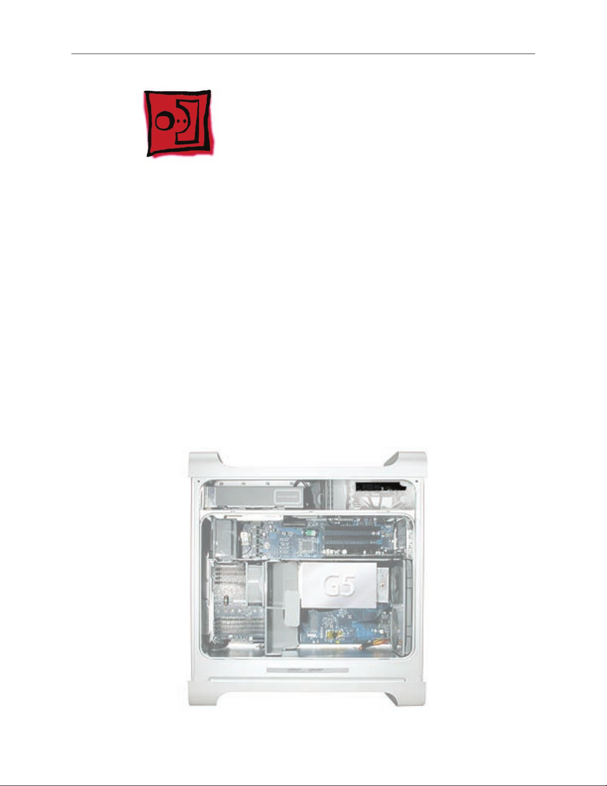
Internal Views, Power Mac G5 21
Overview 214
Logic Board, Power Mac G5 215
4
External Views 216
Front View 216
Rear View 217
Page 7
Service Source
Basics
Power Mac G5
© 2005 Apple Computer, Inc. All rights reserved.
Page 8

Overview
Power Mac G5 is a 64-bit desktop computer powered by the PowerPC G5 processor in uni- or
dual-processor congurations. It offers memory expansion up to 8 GB, front-side bus up to 1.25
GHz, and advanced 64-bit computation, while running existing 32-bit applications natively. The
computer also includes serial ATA hard drives, high-end graphics capabilities, and computercontrolled cooling based on four independent zones.
This manual covers the following Power Mac G5 models: original Power Mac G5, Power Mac G5
(June 2004), and Power Mac G5 (Early 2005). The tables on the next page illustrate the main
differences between these computers. For complete technical specications, refer to
http://www.info.apple.com/support/applespec.html
Power Mac G5 Basics 11
Page 9
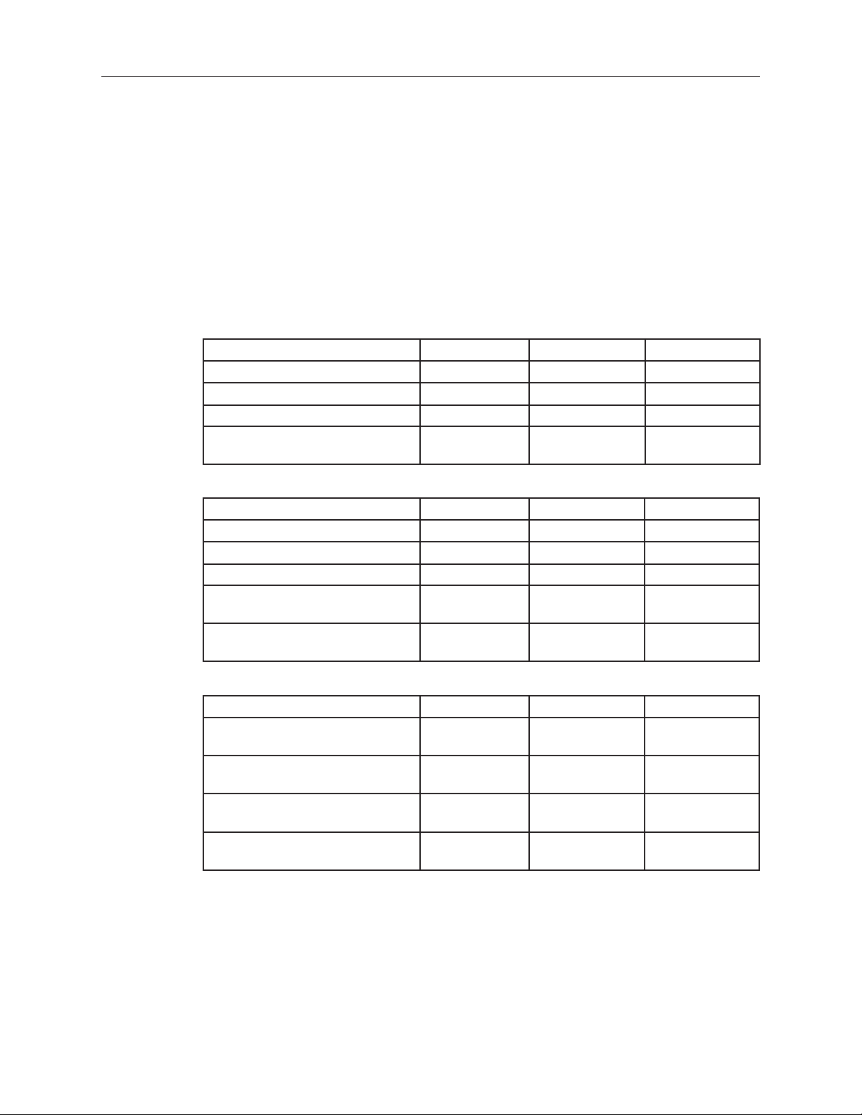
Original Power Mac G5
Original Uni 1.6 GHz Original Uni 1.8 GHz Original Dual 1.8GHz Original Dual 2.0GHz
800 MHz front bus 900 MHz front bus 900 MHz front bus 1 GHz front bus
256 MB DDR333
SDRAM, expandable
to 4 GB
80 GB Serial ATA drive 160 GB Serial ATA
SuperDrive SuperDrive SuperDrive SuperDrive
Three PCI slots Three PCI-X slots Three PCI-X slots Three PCI-X slots
NVIDIA GeForce FX
5200 Ultra video
450 W power supply 450 W power supply 600 W power supply 600 W power supply
56K modem 56K modem 56K modem 56K modem
512 MB DDR400
SDRAM, expandable
to 8 GB
drive
NVIDIA GeForce FX
5200 Ultra video
512 MB DDR400
SDRAM, expandable
to 8 GB
160 GB Serial ATA
drive
NVIDIA GeForce FX
5200 Ultra video
512 MB DDR400
SDRAM, expandable
to 8 GB
160 GB Serial ATA
drive
ATI Radeon 9600 Pro
video
Power Mac G5 (June 2004)
June 2004 Dual 1.8 GHz June 2004 Dual 2.0 GHz June 2004 Dual 2.5 GHz
(with LCS Heasink)
900 MHz front bus 1 GHz front bus 1.25 GHz front bus
256 MB DDR400 SDRAM,
expandable to 4 GB
80 GB Serial ATA drive 160 GB Serial ATA drive 160 GB Serial ATA drive
SuperDrive SuperDrive SuperDrive
Three PCI slots Three PCI-X slots Three PCI-X slots
NVIDIA GeForce FX 5200 Ultra
video
450 W power supply 600 W power supply 600 W power supply
56K modem 56K soft modem 56K soft modem
512 MB DDR400 SDRAM,
expandable to 8 GB
NVIDIA GeForce FX 5200 Ultra
video
512 MB DDR400 SDRAM,
expandable to 8 GB
ATI Radeon 9600 XT video
Power Mac G5 (Early 2005)
Early 2005 Dual 2.0 GHz Early 2005 Dual 2.3 GHz Early 2005 Dual 2.7 GHz
900 MHz front bus 1 GHz front bus 1.25 GHz front bus
512 MB DDR400 SDRAM,
expandable to 8 GB
160 GB Serial ATA drive 250 GB Serial ATA drive 250 GB Serial ATA drive
SuperDrive SuperDrive SuperDrive
Three PCI slots Three PCI-X slots Three PCI-X slots
ATI Radeon 9600 video ATI Radeon 9600 video ATI Radeon 9650 video
450 W power supply 450 W power supply 600 W power supply
12 Power Mac G5 Basics
512 MB DDR400 SDRAM,
expandable to 8 GB
(with LCS Heasink)
512 MB DDR400 SDRAM,
expandable to 8 GB
Page 10
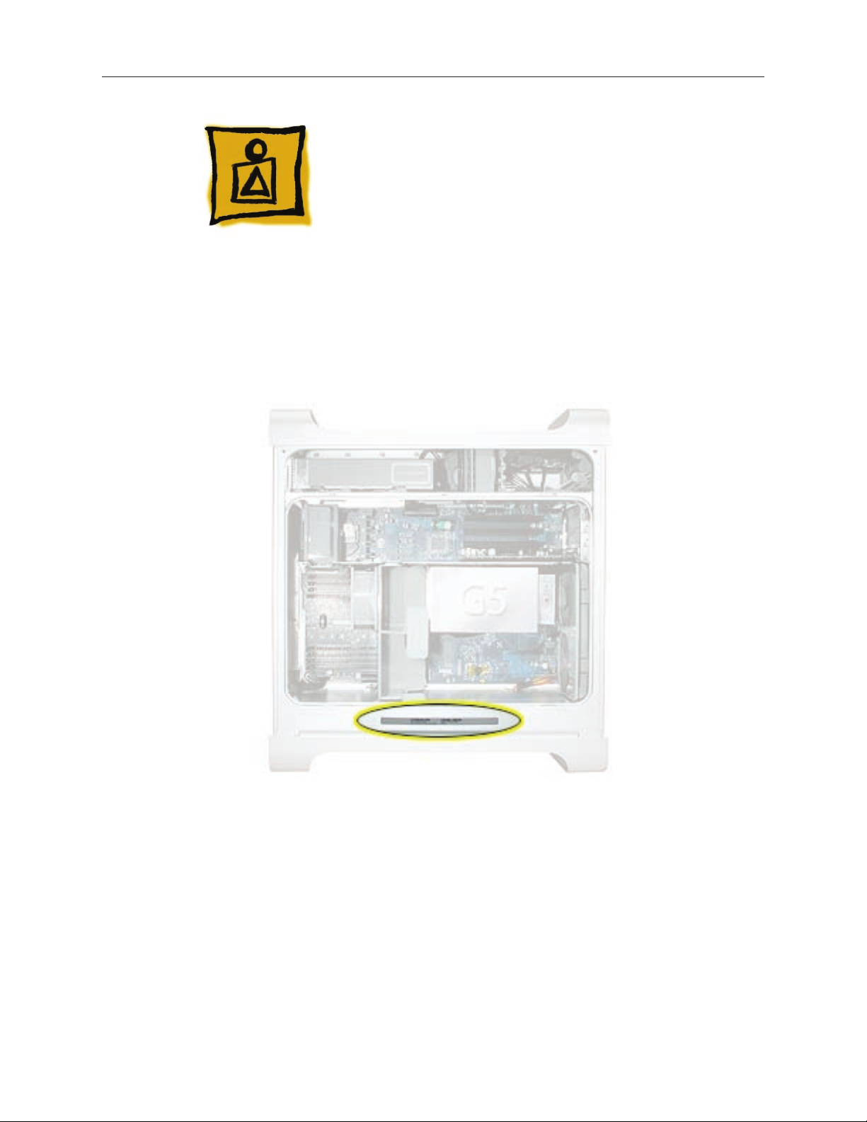
Serial Number Location
To identify a particular model of Power Mac G5, check the computer’s serial number, which lists
the model’s conguration. The serial number is located directly below the air deector inside the
side access panel.
Power Mac G5 Basics 13
Page 11

Features
Overview
PowerPC G5 — The Power Mac G5 computer incudes the new 64-bit PowerPC G5 processor
running at 1.6, 1.8, 2.0, 2.3, 2.5, or 2.7 GHz, well beyond the speeds of G4 processors.
Serial ATA hard drives — Unlike older parallel drives, the new serial ATA drives in the Power Mac
G5 offer up to 150 MB/s data throughput. The 7200 rpm drives come in 80, 160, 250, or 400 GB
capacity.
PCI-X slots — Higher-bandwidth PCI slots allow for greater amounts of data when using
expansion cards that demand high performance. Both 100 and 133 MHz PCI-X slots are included
in higher-end Power Mac G5 computers. For more information, see the “AGP/PCI Card” topic in
the Take Apart chapter.
8x AGP bus — This bus provides a higher amount of data transfer to and from the graphics card.
Both NVIDIA and ATI graphics cards are offered for the Power Mac G5.
USB 2.0 — All USB ports on the Power Mac G5 support the USB 2.0 standard, which
accommodates more high speed peripherals.
Digital audio in and out — The Power Mac G5 introduces two new optical audio (S/PDIF) ports,
allowing for optical audio input and output. These ports are in addition to the existing analog
sound input and output ports.
Cooling zones — Nine case fans and blowers are logically grouped into four separate cooling
zones in the Power Mac G5. Each zone is software-controlled by the system to only cool when
necessary, making for a more efcient (and quieter) cooling solution.
ATA/100 bus for optical drives— This technology allows optical storage to read/write data faster.
Double-layer SuperDrives — Power Mac G5 (Early 2005) 16x SuperDrives support double-layer
(DVD+R DL) discs. Double-layer discs have two layers of data, allowing the SuperDrive to read
and write on either layer, almost doubling the storage to 8.5GB.
Interleaved DDR RAM —The Power Mac G5 requires pairs of DIMMs, which improves
performance. Different models require either DDR 333 or DDR 400 RAM. DIMMs must be installed
in pairs of equal size and kind. For more information, see the “Memory (DIMMs)” topic in the Take
Apart chapter.
Liquid Cooling System — The Power Mac G5 (June 2004 Dual 2.5 GHz and Early 2005 Dual 2.7
14 Power Mac G5 Basics
Page 12
GHz) models feature a liquid cooling system that is more efcient than a traditional heat sink.
This system provides a continuous ow of thermally conductive uid that transfers heat from the
processors. The heated uid then ows through a radiant grille, where air passing over cooling
ns returns the uid to its original temperature.
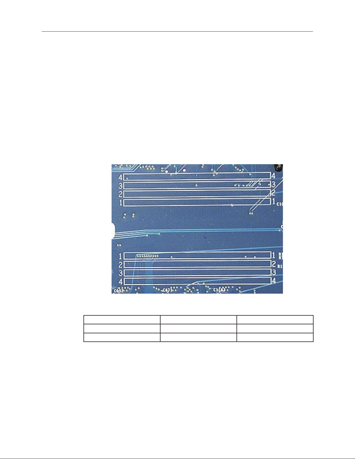
DDR Memory
Depending on the model, Power Mac G5 computers have either four or eight Dual Inline Memory
Module (DIMM) slots for Double-Data-Rate (DDR) Synchronous Dynamic Random-Access Memory
(SDRAM) devices. The computers ship with a minimum of 256 MB of RAM, installed as a pair of
128 MB DIMMs in two of the DIMM slots. You can install additional DIMMs, provided they are
installed in pairs of equal size. A diagram marked on the logic board near the slots illustrates how
the pairs must be installed.
To determine the types of DIMMs to install, refer to the table below:
DIMM Slots DIMM Speed Maximum Amount
4 (two banks of 2 slots) 333 MHz, PC 2700 up to 4 GB
8 (two banks of 4 slots) 400 MHz, PC 3200 up to 8 GB
In addition, DIMMs must t these specications:
2.5 volt
•
184-pin module
•
Maximum number of memory devices on DDR SDRAM:16
•
Nonparity
•
Non-error-correcting (NECC)*
•
*Note: Although they do not take advantage of error-correcting (ECC) RAM features, Power Mac
G5 computers can also use ECC memory.
Power Mac G5 Basics 15
Page 13
Video
The Power Mac G5 computer comes with a graphics card installed in the AGP slot. All graphics
cards support dual displays in either extended desktop or video mirroring mode.
The display memory on the AGP card is separate from the main memory. The display memory
consists of 64, 128, or 256 MB of DDR video SDRAM. The display memory cannot be expanded by
the user.
The following table lists the standard and CTO graphics cards used in Power Mac G5 computers.
(Port 1 indicates the connector that is next to the logic board when the card is installed.)
Original G5 Graphics Cards Video SDRAM Port 2 Port 1
NVIDIA GeForce FX 5200 Ultra 64 MB DDR DVI ADC
ATI Radeon 9600 Pro 64 MB DDR DVI ADC
ATI Radeon 9800 Pro 128 MB DDR DVI ADC
NVIDIA GeForce 6800 Ultra DDL* 256 MB DDR dual-link DVI
TV out
June 2004 G5 Graphics Cards Video SDRAM Port 2 Port 1
NVIDIA GeForce FX 5200 Ultra 64 MB DDR DVI ADC
ATI Radeon 9600 XT 128 MB DDR DVI ADC
ATI Radeon 9800 XT* 256 MB DDR DVI ADC
NVIDIA GeForce 6800 GT DDL* 256 MB DDR dual-link DVI
TV out
NVIDIA GeForce 6800 Ultra DDL* 256 MB DDR dual-link DVI
TV out
dual-link DVI
TV out
dual-link DVI
TV out
dual-link DVI
TV out
Early 2005 G5 Graphics Cards Video SDRAM Port 2 Port 1
ATI Radeon 9600 128 MB DDR single-link DVI single-link DVI
ATI Radeon 9650 256 MB DDR dual-link DVI single-link DVI
NVIDIA GeForce 6800 Ultra DDL* 256 MB DDR dual-link DVI
ATI Radeon X850 XT 256 MB DDR dual-link DVI
* Due to its large size, this card occupies both the AGP slot and the adjacent PCI slot. For this
reason, the number of available PCI slots is reduced from three to two.
16 Power Mac G5 Basics
TV out
TV out
TV out
TV out
dual-link DVI
TV out
ADC
Page 14

Fan Controller
The Power Mac G5 system employs advanced thermal management to keep acoustic noise to
a minimum. The system is divided into discrete zones, each with independently controlled fans
bringing in cool air from the front of the enclosure, directing it through ducts and exhausting it
out the rear. Temperature and power consumption are monitored by the operating system, which
communicates with the Fan Control Unit, which in turn controls and monitors fan operation. Note
that if Mac OS X is not booted, thermal management will not work correctly.
Important: To ensure proper fan and temperature control, you must run Apple Service
Diagnostic whenever you replace a processor or logic board with a new processor or logic board.
You must also run the diagnostic if you re-install the same processor but in a different connector
from the one in which it was originally installed. For more information, see “Thermal Calibration”
in the Troubleshooting chapter.
Optical Audio
Digital data is transmitted to and from the optical audio I/O using special optical cables. The 7.5
mm digital optical connectors on the cables, commonly referred to as TOSLink, are for both input
and output and conform to the IEC60874-17 connector standard.
The TOSLink friction-lock type F-05 connectors are available from pro-audio, musician’s supply, hi-
, and other retailers.
Analog audio signals are converted to digital data internally. All audio is handled digitally inside
the computer, including audio data from the CD or DVD drive and from devices connected to the
USB and FireWire ports. Audio data is converted to analog form for output to the internal speaker,
the headphones, or the analog output port.
Wireless
The Power Mac G5 supports wireless networking with an AirPort Extreme Card and AirPort
Extreme Base Station or AirPort Express. AirPort Extreme uses the 802.11g wireless standard to
deliver data rates up to 54 Mbps.
The Power Mac G5 also supports an optional internal Apple Bluetooth module. Bluetooth
technology enables short-range wireless connections between desktop and laptop computers
and other peripheral devices such as cell phones, PDAs, and printers. Support for Bluetooth is
built into Mac OS X and compliant with Bluetooth specication v1.1. It operates on a globally
available 2.4 GHz frequency band (ISM band) for worldwide compatibility and has a maximum
throughput of 1 Mbps.
Important: For proper range and operation, the external Bluetooth antenna and external AirPort
antenna must be attached to the Bluetooth and AirPort ports on the back of the Power Mac G5.
Power Mac G5 Basics 17
Page 15

Ports
The following ports are included on the front and back panels of the Power Mac G5. For
illustrations of the port locations, see the “External Views” topic in the Views chapter.
Front
Power button
•
Headphone port
•
USB 2.0 port
•
FireWire 400 port
•
Rear
AirPort antenna port
•
Bluetooth antenna port
•
Optical audio-out port
•
Optical audio-in port
•
Audio line-out port
•
Audio line-in port
•
USB 2.0 ports (two ports)
•
FireWire 400 port
•
FireWire 800 port
•
10/100/1000Base-T Ethernet port
•
Modem port
•
18 Power Mac G5 Basics
Page 16

Service Source
Take Apart
Power Mac G5
© 2005 Apple Computer, Inc. All rights reserved.
Page 17

General Information
Orientation
For most take-apart procedures, it is recommended that you lay the computer on its side before
removing or installing the part. For proper operation, however, Apple recommends that the
unit be run in the upright position. The computer should never be operated on its side with the
access panel facing down.
Tools
The following tools are required to service the computer:
Long-handled magnetic Phillips screwdriver (10-inch shaft)
•
Short-handled magnetic Phillips screwdriver
•
Flatblade screwdriver
•
Jeweler’s atblade screwdriver
•
Nylon probe tool (black stick 922-5065)
•
Needlenose pliers
•
Small wire cutter
•
Long-handled 2.5 mm hex wrench
•
Mat knife and cup hook (to remove locking rivet)
•
Tape (for temporarily holding cables out of the way)
•
Small mirror (for seeing small boards inside the enclosure)
•
Soft cloth (for protect removed parts from scratches)
•
Parts Requiring Enclosure Replacement
The following are not separate, orderable parts. To replace them, you must replace the enclosure.
Media blower
•
Media fan
•
Hard drive locking latches
•
Hard drive bay
•
Optical drive levers
•
Media shelf
•
Power harness cable, including hard drive power cables
•
Media bay sensor and air deector sensor cable
•
Rear panel latch
•
Power Mac G5 Take Apart 21
Page 18

Take Apart Procedures
This manual covers several different Power Mac G5 models. Some models may look slightly
different from the one shown in the illustrations; however, except where indicated, the following
procedures apply to all models.
22 Power Mac G5 Take Apart
Page 19

Opening the Computer
Tools
No tools are required for this procedure.
Preliminary Steps
Shut down the computer.
1.
Warning: Always shut down the computer before opening it to avoid damaging its internal
components or the components you are installing. Do not open the computer or attempt to
install items inside it while it is on.
Wait 5 to 10 minutes to allow the computer’s internal components to cool.
2.
Warning: After you shut down the system, the internal components can be very hot. You
must let the computer cool down before continuing.
Unplug all external cables from the computer except the power cord.
3.
Touch the metal PCI access covers on the back of the computer to discharge any static
4.
electricity from your body.
Important: Always discharge static before you touch any parts or install any components
inside the computer. To avoid generating static electricity, do not walk around the room until
you have nished working and closed the computer.
Unplug the power cord.
5.
Warning: To avoid damaging its internal components or the components you want to
install, always unplug the computer before attempting any take-apart procedure.
Put on an ESD wrist strap.
6.
Power Mac G5 Take Apart 23
Page 20
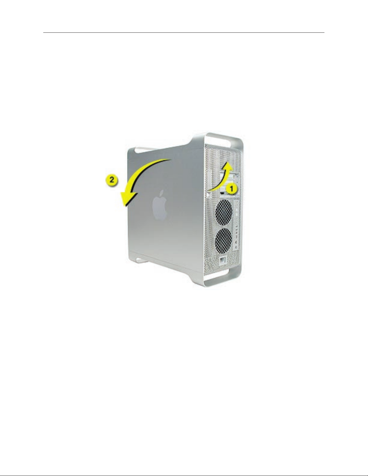
Procedure
Hold the side access panel and lift the latch on the back of the computer.
1.
Warning: The edges of the access panel and the enclosure can be sharp. Be very careful
when handling them.
Remove the access panel and place it on a at surface covered by a soft, clean cloth.
2.
Replacement Note: Make sure the latch is in the up position before replacing the access
panel. If the latch is down, the access panel will not seat correctly in the enclosure.
24 Power Mac G5 Take Apart
Page 21
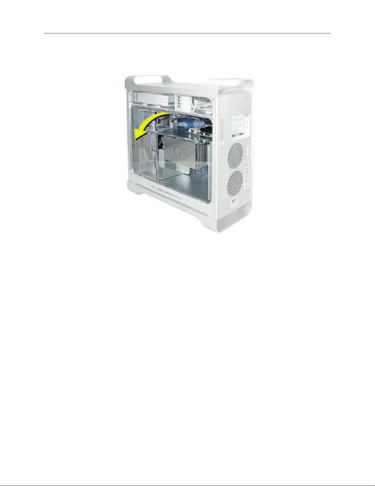
Remove the air deector and place it on a soft, clean cloth.
3.
Replacement Note: To replace the air deector, insert the three tabs on the bottom edge of the
deector into the three slots in the bottom frame of the enclosure. Then swing the deector up
ush against the top frame of the enclosure.
Important: Make sure you re-install the air deector before replacing the access panel. If the air
deector is not installed, the computer will not function properly.
Power Mac G5 Take Apart 25
Page 22
Serial ATA Hard Drive
The Power Mac G5 computer can accommodate two serial ATA hard drives in its internal hard
drive bay. In most congurations, a single hard drive occupies the top portion of the bay. You can
install one additional serial ATA hard drive to the empty slot in the bay.
Important: Use the original Apple cables that came with the Power Mac G5 when installing ATA
hard drives.
Tools
The only tool required for this procedure is a Phillips screwdriver.
Preliminary Steps
Before you begin, open the computer.
Part Location
Power Mac G5 Take Apart 27
Page 23
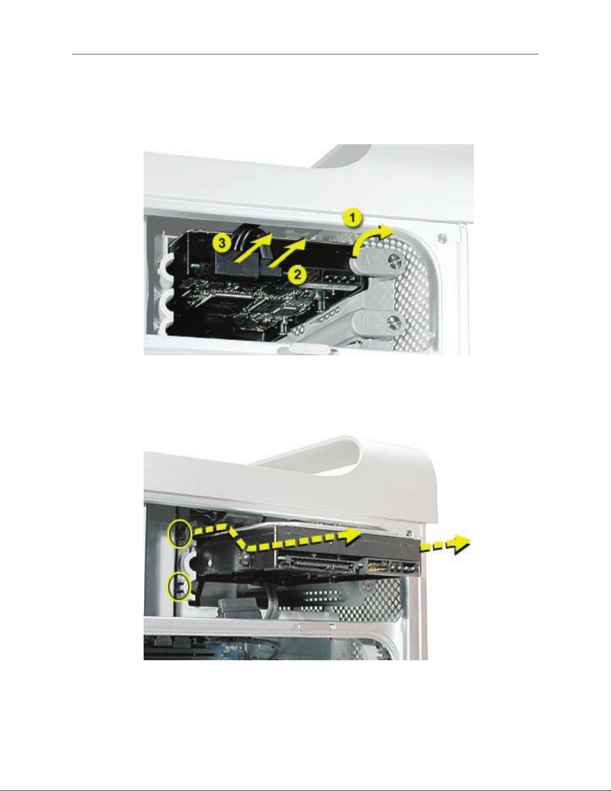
Procedure
Release the drive locking latch by rotating it up.
1.
Disconnect the drive data cable and power cable from the hard drive.
2.
Pull the drive out of the drive bay, being careful not to touch the bottom of the drive.
3.
Note: If you encounter resistance, use a atblade screwdriver to release the latches on the
drive bay rails as you pull the drive out of the bay. (See circled areas on the illustration
below.) If two drives are installed, remove the bottom drive rst.
Important: If the printed circuit board (PCB) is exposed on the bottom of the hard drive,
hold the drive by its sides. To avoid damaging the replacement drive, take care not to touch
the PCB during installation.
28 Power Mac G5 Take Apart
Page 24
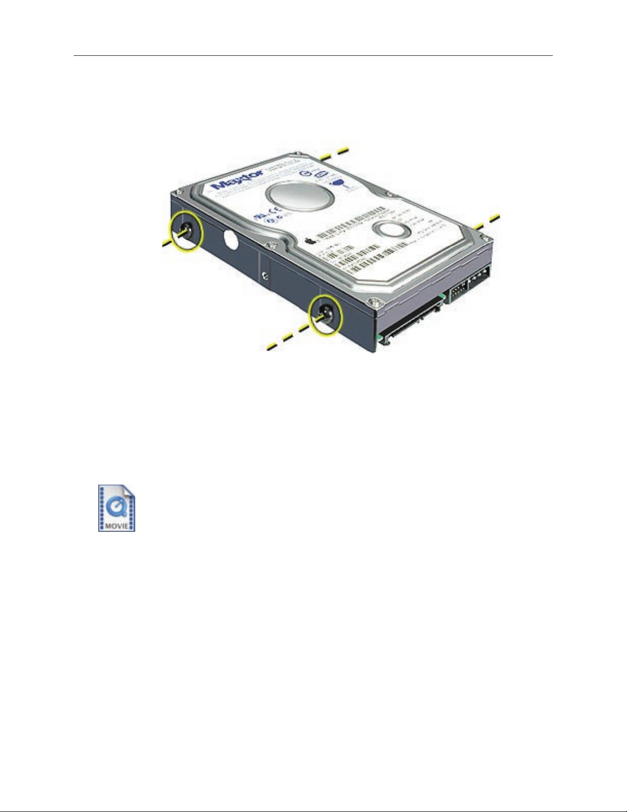
Replacement Note: If you are replacing a hard drive with a new drive, transfer the four guide
screws from the sides of the original drive to the new drive. If you are installing an additional
drive, transfer the guide screws from the side of the hard drive bay to the drive
Replacement Note: When replacing the top drive, make sure the guide screws align with the
middle slot of the drive bay, and then gently push the drive into the bay until it snaps into place.
When installing a bottom drive, align the guide screws with the bottom slot of the drive bay and
slide the drive in until it snaps into place.
Power Mac G5 Take Apart 29
Page 25
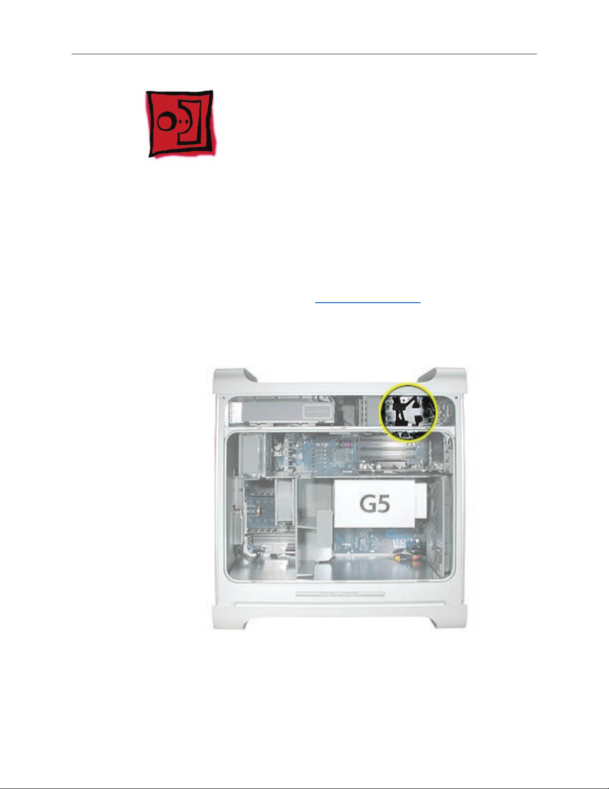
Serial ATA Hard Drive Data Cable
Tools
The only tool required for this procedure is a small wire cutter.
Preliminary Steps
Before you begin, open the computer and remove the hard drive(s).
Part Location
30 Power Mac G5 Take Apart
Page 26
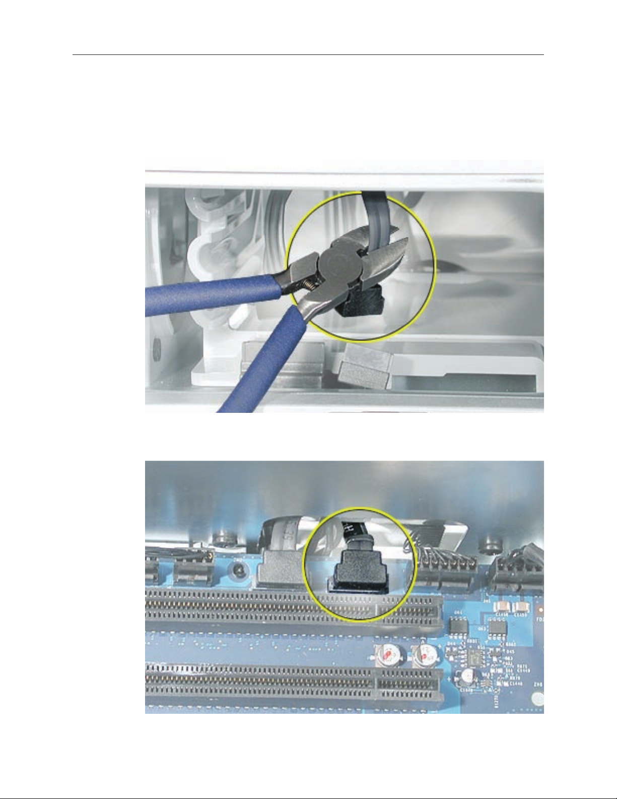
Procedure
Upper Hard Drive Cable
Clip off the connector from the hard drive end of the upper hard drive data cable.
1.
Disconnect the cable from the logic board, pull the cable out of the hard drive bay, and
2.
remove the cable from the enclosure.
Power Mac G5 Take Apart 31
Page 27
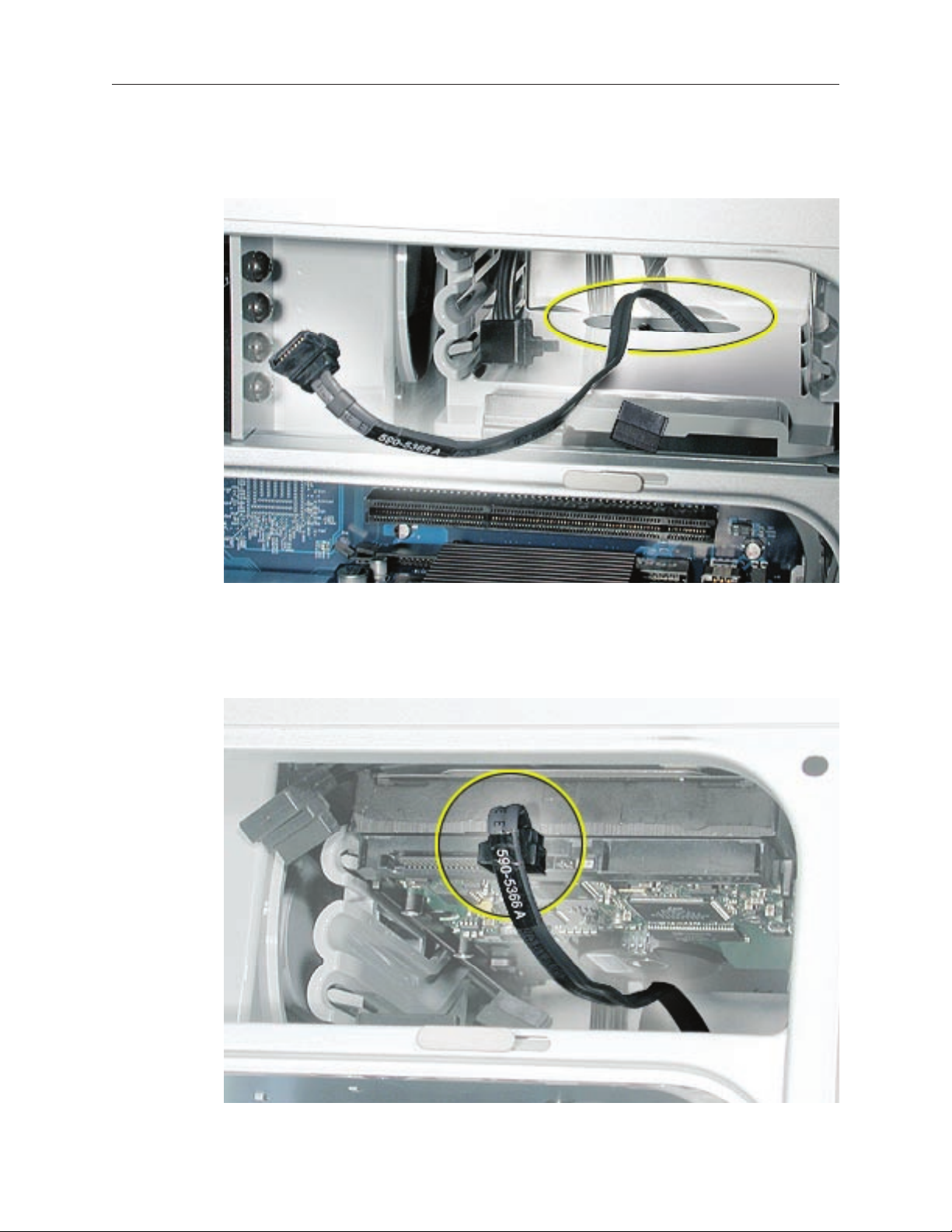
Replacement Note: When installing the replacement upper hard drive cable, rst route the cable
through the opening in the hard drive bay.
Then install the upper hard drive with the cable routed below the drive, and connect the cable to
the drive as illustrated.
32 Power Mac G5 Take Apart
Page 28
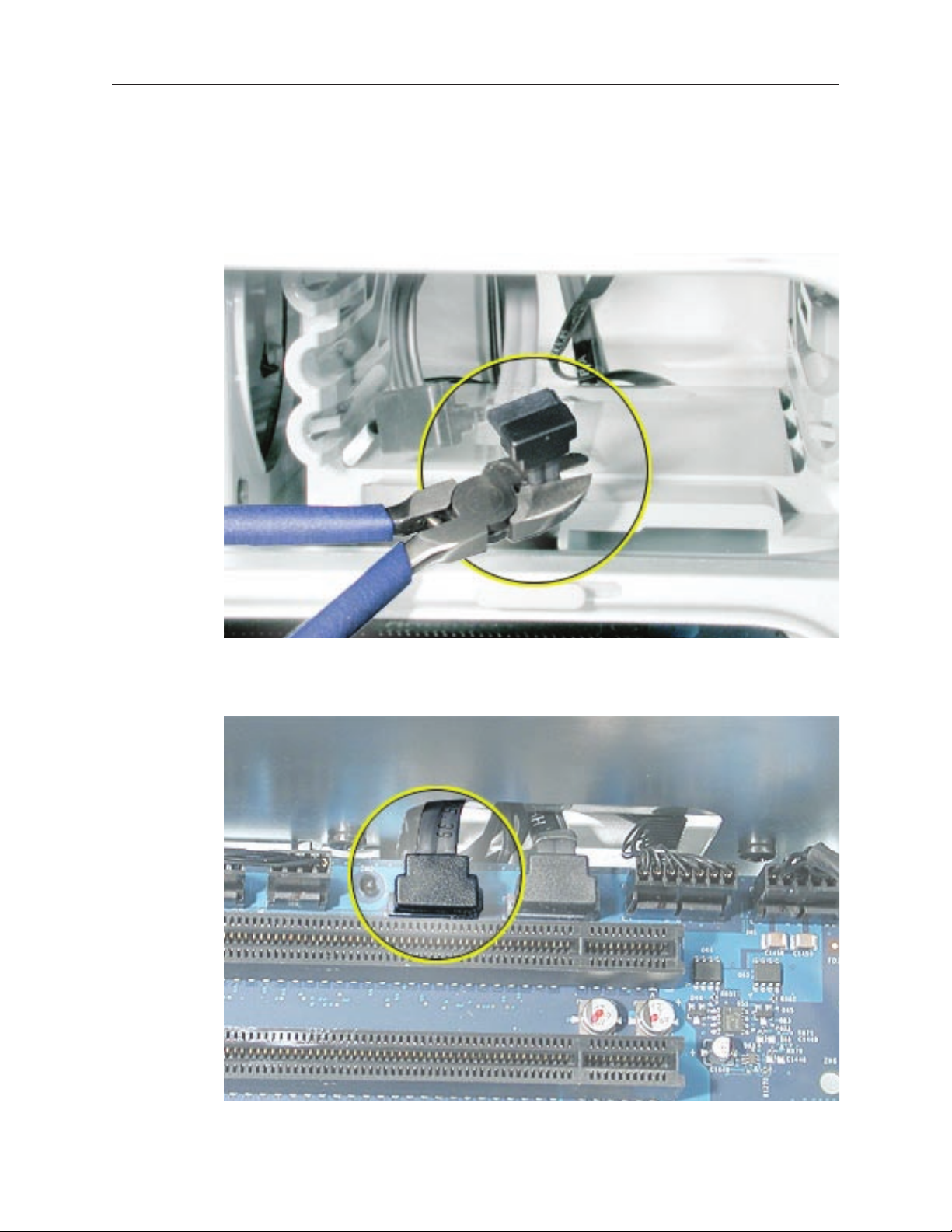
Lower Hard Drive Cable
Clip off the connector from the hard drive end of the lower hard drive cable.
1.
Disconnect the cable from the logic board, pull the cable out of the hard drive bay, and
2.
remove the cable from the enclosure.
Power Mac G5 Take Apart 33
Page 29
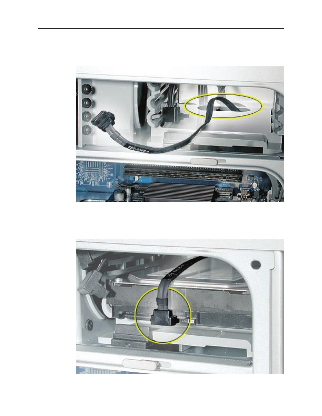
Replacement Note: When installing the replacement lower hard drive cable, rst route the cable
through the opening in the hard drive bay.
Then install the lower hard drive with the cable routed above the drive, and connect the cable to
the drive as illustrated.
34 Power Mac G5 Take Apart
Page 30
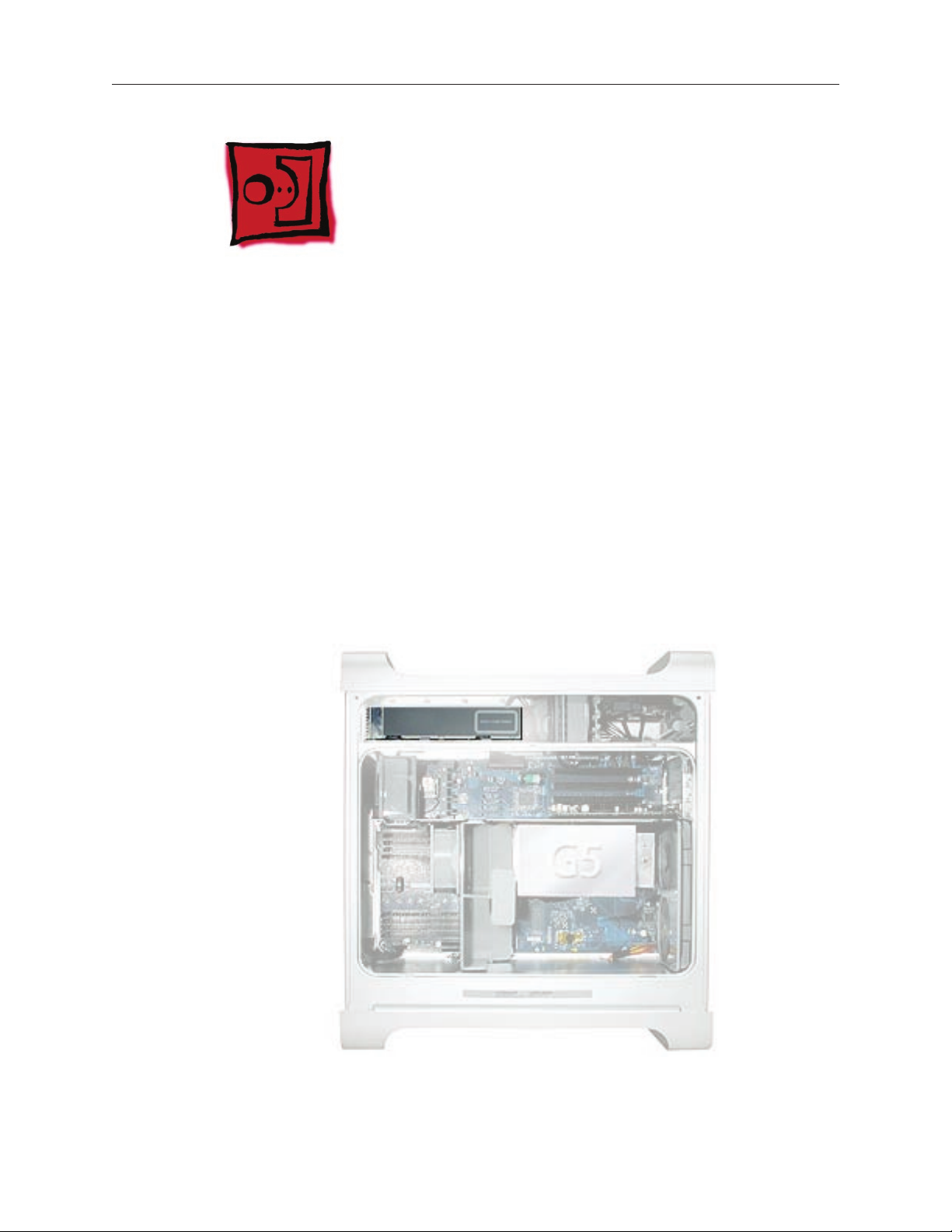
Optical Drive
Important: When installing a replacement optical drive, use the original Apple cables that came
with the Power Mac G5.
Tools
No tools are required for this procedure.
Preliminary Steps
Before you begin, open the computer.
Part Location
Power Mac G5 Take Apart 35
Page 31

Procedure
Disconnect the optical drive ribbon cable from the logic board. (The cable connector is
1.
located under the media shelf that holds the optical drive.)
Push the optical drive levers out to release the drive.
2.
36 Power Mac G5 Take Apart
Page 32

Place the ngers on one hand inside the opening for the optical drive cable and push the
3.
edge of the drive forward. The drive will move part way out of the media shelf.
Disconnect the power cable from the drive.
4.
Route the drive ribbon cable out through the opening in the media shelf and remove the
5.
drive and ribbon cable from the computer.
Power Mac G5 Take Apart 37
Page 33

If you are replacing the drive with a new drive, install the standoffs on the bottom of the
6.
new drive.
Note for SuperDrives: Two bags of standoffs are included with each drive. Use the standoffs
with a Phillips head on Sony drives; use the standoffs with a hex head on Toshiba and
Pioneer drives.
Note for Combo Drives: Use only the standoffs that are included with the new drive. Do not
transfer the standoffs from the original drive to the replacement drive.
38 Power Mac G5 Take Apart
Page 34

Disconnect the ribbon cable from the back of the drive, and then carefully pry the cable
7.
from the top of the drive. Transfer the cable to the top of the replacement drive, and connect
the cable to the drive.
Note: Reusable adhesive tape on the underside of the cable attaches the cable to the drive.
When removing the cable from the original drive, be careful to keep the tape with the cable.
Carefully remove the EMI shield from the front of the original drive and transfer it to the
8.
front of the replacement drive.
Replacement Note: Insert the optical drive part way into the optical drive bay, and connect the
power cable to the drive. Then bend down the free end of the ribbon cable, route it through the
opening at the back of the media shelf, and connect the cable to the logic board.
Power Mac G5 Take Apart 39
Page 35

Front Inlet Fan(s)
The front inlet fan assembly consists of one or two fans in a plastic bracket. If the computer is a
uniprocessor, the assembly contains a single fan; if the computer is a dual processor, the assembly
contains two fans connected by a single cable.
You must remove the front inlet fan assembly to access many other parts within the computer.
For this access, remove the bracket with the fans attached. You will have to remove the fans from
the bracket only if you are replacing the fans themselves.
Tools
The only tool required for this procedure is needlenose pliers.
Preliminary Steps
Before you begin, open the computer and lay it on its side with the access side facing up.
Part Location
40 Power Mac G5 Take Apart
Page 36

Procedure
Hold the front inlet fan assembly by the front handle and rmly pull it out of the computer.1.
Power Mac G5 Take Apart 41
Page 37

If you are replacing the fan(s) in the bracket, do the following:
2.
• Remove the fan cable from the cable guide.
• Using needlenose pliers, pull the fan(s) off the grommet fasteners, and remove the fan(s)
and cable from the bracket.
Important: If you are replacing two fans, be careful that you do not separate the fans from
each other. They are connected by a common cable.
42 Power Mac G5 Take Apart
Page 38

Replacement Note: To replace the front inlet fan bracket in the enclosure, align the large rail on
the bracket with the cutout in the PCI divider and press rmly.
Important: Make sure the connector on the fan fully engages the fan connector on the logic
board, or the computer will not operate properly. Gently pull the fan assembly to test whether it
is connected.
Power Mac G5 Take Apart 43
Page 39

Memory (DIMMs)
Depending on the model, Power Mac G5 computers have either four or eight Dual Inline
Memory Module (DIMM) slots arranged in two banks. The slots accept Double-Data-Rate (DDR)
Synchronous Dynamic Random-Access Memory (SDRAM) devices.
The computers ship with a minimum of 256 MB of RAM, provided by a pair of 128 MB DIMMs
installed in slot 1 of each DIMM bank. You can add DIMMs, provided they are installed in pairs of
equal size, one per bank, from the center outward. A diagram marked on the logic board near the
DIMM slots illustrates how the pairs must be installed.
To determine the types of DIMMs to install, refer to the table below:
DIMM Slots DIMM speed Maximum amount
4 333 MHz, PC 2700 up to 4 GB
8 400 MHz, PC 3200 up to 8 GB
44 Power Mac G5 Take Apart
Page 40

In addition, DIMMs must t these specications:
2.5 volt
•
184-pin module
•
Maximum number of memory devices on DDR SDRAM:16.
•
Nonparity
•
No error correcting codes (ECC)
•
Unbuffered (registered or buffered DDR SDRAM cannot be used)
•
Important: Always install DIMMs in pairs of equal size. Memory from older computers is not
compatible with the Power Mac G5. Do not use older memory, even if it ts into the DIMM slots.
Note: The Power Mac G5 (June 2004/Early 2005) models support only 184-pin, 2.5 volt,
DDR400-compliant (PC3200) DRAM DIMMs with a maximum of 4 GB or 8 GB depending on the
conguration.
Tools
No tools are required for this procedure.
Preliminary Steps
Before you begin, open the computer, lay it on its side with the access side facing up, and
remove the front inlet fan assembly.
Part Location
Power Mac G5 Take Apart 45
Page 41

Procedure
1. Locate the DIMM slots on the logic board.
1.
2.
2. Open the ejectors on the DIMM slot by pushing them out to the sides.
3.
3. Holding the DIMM by both top corners, lift it straight up out of the computer.
Replacement Note: Align the DIMM in the slot and push both ends of the DIMM down until the
tabs are vertical and the ejectors snap into place.
Important: Do not touch the DIMM connectors. Handle the DIMM only by the edges.
46 Power Mac G5 Take Apart
Page 42

AGP/PCI Card
AGP Slot 1
PCI Slot 2
PCI Slot 3
PCI Slot 4
The Power Mac G5 computer has four expansion card slots, three of which accommodate
Peripheral Component Interconnect (PCI) cards and one that accepts an advanced graphics port
(AGP) video card. AGP cards and PCI cards have different connectors, so you cannot insert a PCI
card into the AGP slot.
Note: Maximum power consumption for all four expansion slots (the three PCI expansion cards
and the AGP card) should not exceed 90 watts (W).
AGP Cards
The AGP video card, installed in slot 1, contains the graphics processor unit (GPU) and provides
the computer’s display ports. Slot 1 is designed specically to accept AGP cards.
Note: If certain high-end video cards are installed in the AGP slot, the cards block the adjacent
PCI/PCI-X slot (slot 2). As a result, you can install PCI/PCI-X cards in slots 3 and 4 but not in slot 2.
For specic card information, see the video card table in the “Video” topic in the Basics chapter.
The Power Mac G5 (June 2004/Early 2005) models have the accelerated graphics port (AGP 8x
Pro) bus. It’s an enhanced PCI bus with extra functionality that is up to 8 times faster than a 66
MHz PCI port. The computer comes with a graphics card installed in the AGP 8x Pro slot and has
ADC and DVI-I connectors or dual DVI-I connectors. The AGP bus is 1.5 V only and is not backward
compatible. Older AGP cards will not work in these models.
Power Mac G5 Take Apart 47
Page 43

PCI Cards
The remaining three expansion slots, labeled 2, 3, and 4, accommodate PCI cards up to 12 inches
long. Depending on the Power Mac G5 model, you can install either PCI or PCI-X cards.
Note: To determine if a Power Mac G5 computer can accommodate PCI-X cards, check the
number of DIMM slots on the logic board. Computers with four DIMM slots have 33 MHz PCI slots
and cannot use PCI-X cards; computers with eight DIMM slots can accommodate 100 and 133
MHz PCI-X cards. See the chart below.
Card type PCI slot Card speed
PCI* slots 2, 3, and 4 64-bit, 33 MHz
PCI-X slots 2 and 3 64-bit, 100 MHz
PCI-X slot 4 64-bit, 133 MHz
*The PCI slots can accommodate mixed-voltage (5.0 V, 12 V, or 3.3 V) cards but only at 3.3 V
signaling, with 32-bit or 64-bit data widths and a 33 MHz frequency. You can add a 66 MHz card
to a 33 MHz PCI slot if the card can operate at the lower 33 MHz rate.
Warning: Do not use PCI cards that function only at 66 MHz in the PCI slots. Damage to the
equipment could result. If you are installing an additional 66 MHz PCI card, rather than replacing
an existing PCI card like-for-like, check with the card’s manufacturer to see if the new 66 MHz
card also works at 33 MHz.
48 Power Mac G5 Take Apart
Page 44

Tools
The only tool required for this procedure is a Phillips screwdriver.
Preliminary Steps
Before you begin, open the computer and lay it on its side with the access side facing up.
Part Location
Procedure
Install an AGP video card in slot 1 only. Install either PCI or PCI-X cards in the slots labeled 2, 3,
and 4.
Warning: When removing or installing a PCI or AGP card, handle it only by the edges. Do not
touch its connectors or any of the components on the card. Lift the card straight out from the
connector to remove it, and insert it straight into the connector to install it. Do not rock the card
from side to side and don’t force the card into the slot. Once the replacement card is installed,
pull on it gently to check that it is properly connected.
Power Mac G5 Take Apart 49
Page 45

Remove the screw that mounts the card to the enclosure.
1.
If you are removing an AGP card, pull back the small locking clip at the front of the AGP
2.
connector.
Holding the card by the top corners, gently pull up the card and remove it from its
3.
expansion slot.
Replacement Note: Align the card’s connector with the expansion slot and press until the
connector is inserted all the way into the slot. If you’re installing a 12-inch card, make sure the
card engages the appropriate slot in the PCI card guide.
Don’t rock the card from side to side; instead, press the card straight into the slot.
•
Don’t force the card. If you meet a lot of resistance, pull the card out. Check the connector
•
and the slot for damage or obstructions, then try inserting the card again.
Pull the card gently to see if it is properly connected. If it resists and stays in place, and if its
•
gold connectors are barely visible, the card is connected.
50 Power Mac G5 Take Apart
Page 46

AirPort Extreme Card
Only the AirPort Extreme Card may be installed in the Power Mac G5. Older AirPort Cards do not
work in this computer.
Tools
No tools are required for this procedure.
Preliminary Steps
Before you begin, open the computer and lay it on its side with the access side facing up.
Part Location
Power Mac G5 Take Apart 51
Page 47

Procedure
Carefully disconnect the antenna cable from the end of the AirPort Extreme Card.
1.
Pull the card straight back out of the enclosure.
2.
Replacement Note: Position the AirPort Extreme Card with the ID numbers and barcode facing
the bottom case and insert the card into the AirPort Extreme Card connector.
Important: Be sure to reconnect the antenna cable to the card.
52 Power Mac G5 Take Apart
Page 48

Battery
Tools
No tools are required for this procedure. You may, however, nd a at-blade screwdriver useful in
removing the battery from its holder.
Preliminary Steps
Before you begin, open the computer and lay it on its side with the access side facing up. If a PCI
card is installed in the slot next to the battery, remove the card.
Part Location
Power Mac G5 Take Apart 53
Page 49

Procedure
1.
If necessary, carefully spread the tabs holding the battery.
2.
Remove the battery from its holder, noting the orientation of the battery’s positive end. (A
plus sign is marked on or near the battery holder.)
Replacement Note: Insert the new battery in the holder, making sure the battery’s positive
symbol aligns with the positive symbol on or near the holder.
Warning: Installing the battery incorrectly may cause an explosion. Be sure the battery’s positive
and negative poles are correctly oriented in the holder. Use only the same type of battery or an
equivalent recommended by the manufacturer of the original.
Important: Batteries contain chemicals, some of which may be harmful to the environment.
Please dispose of used batteries according to your local environmental laws and guidelines.
54 Power Mac G5 Take Apart
Page 50

PCI Card Guide
Tools
The only tool required for this procedure is a Phillips screwdriver.
Preliminary Steps
Before you begin, open the computer and lay it on its side with the access side facing up.
Part Location
Power Mac G5 Take Apart 55
Page 51

Procedure
1.
Remove the two screws that mount the PCI card guide to the logic board.
2.
Slide the card guide up to release the two latches from the PCI divider, and remove the card
guide from the enclosure.
56 Power Mac G5 Take Apart
Page 52

Speaker/Fan Assembly
Tools
The only tools required for this procedure are a Phillips screwdriver and needlenose pliers.
Preliminary Steps
Before you begin, open the computer, lay it on its side with the access side facing up, and
remove the PCI card guide.
Part Location
Power Mac G5 Take Apart 57
Page 53

Procedure
1.
Disconnect the speaker and fan cables from the logic board.
2.
Lift the speaker/fan assembly straight up and remove it from the enclosure.
Important: Be careful that the fan and speaker cables do not catch on the PCI divider as you
lift the assembly.
3.
If you are replacing the speaker, remove the two screws and remove the speaker from the
speaker/fan bracket.
58 Power Mac G5 Take Apart
Page 54

If you are replacing the fan, use needlenose pliers to pull the fan off the four grommet
4.
fasteners. Then remove the fan from the bracket.
Replacement Note: When reinstalling the speaker/fan bracket in the enclosure, make sure the
large tab on the side of bracket engages with the channel in the PCI divider.
Power Mac G5 Take Apart 59
Page 55

Modem: Power Mac G5, Power Mac G5 (June 2004 Dual 1.8 GHz)
Tools
The only tool required for this procedure is a Phillips screwdriver.
Preliminary Steps
Before you begin, open the computer, lay it on its side with the access side facing up, and
remove the speaker/fan assembly.
Part Location
60 Power Mac G5 Take Apart
Page 56

Procedure
Remove the two screws that secure the modem board.
1.
Lift the board slightly and disconnect the modem lter cable from the modem board.
2.
Remove the modem from the enclosure.
3.
Important: Be sure to reconnect the modem lter cable before reinstalling the modem.
Power Mac G5 Take Apart 61
Page 57

Soft Modem: Power Mac G5 (June 2004 Dual 2.0/2.5 GHz), Power Mac G5 (Early 2005)
Tools
The only tool required for this procedure is a Phillips screwdriver.
Preliminary Steps
Before you begin, open the computer, lay it on its side with the access side facing up, and
remove the speaker/fan assembly.
Part Location
62 Power Mac G5 Take Apart
Page 58

Procedure
Remove the two screws that secure the modem board.
1.
Disconnect the board from the connector on the logic board. Disconnect the modem lter
2.
cable from the modem board.
Power Mac G5 Take Apart 63
Page 59

Bluetooth Card
Tools
The only tool required for this procedure is a Phillips screwdriver.
Preliminary Steps
Before you begin, open the computer, lay it on its side with the access side facing up, and
remove the speaker/fan assembly.
Part Location
64 Power Mac G5 Take Apart
Page 60

Procedure
Remove the two Bluetooth mounting screws.
1.
Lift the Bluetooth card straight up a short distance to disconnect it from the logic board.
2.
Then turn the card over, and disconnect the Bluetooth antenna cable from the underside of
the card.
Replacement Note: Be very careful connecting the antenna cable to the Bluetooth card. The
connector is fragile and can easily be bent.
Power Mac G5 Take Apart 65
Page 61

Heatsink Cover: Power Mac G5
Tools
No tools are required for this procedure.
Preliminary Steps
Before you begin, open the computer, lay it on its side with the access side facing up, and
remove the front inlet fan assembly.
Part Location
66 Power Mac G5 Take Apart
Page 62

Procedure
Note: The heatsink cover is held in place by two sets of small plastic latches on the underside of
the cover.
Place both index ngers under the edge of the heatsink cover near the “G” and press in on
1.
the rst set of latches.
Release the second set of latches under the opposite edge of the cap and lift the cover off
2.
the heatsink.
Power Mac G5 Take Apart 67
Page 63

Heatsink Cover: Power Mac G5 (June 2004/Early 2005)
Tools
This procedure requires the following tools:
Mat knife or Xacto knife (to remove locking rivet)
•
Cup hook (to remove locking rivet)
•
Preliminary Steps
Before you begin, open the computer, lay it on its side with the access side facing up, and
remove the front inlet fan assembly.
Part Location
68 Power Mac G5 Take Apart
Page 64

Procedure
Locate the locking rivet that secures the processor heatsink cover to the PCI divider.
1.
Using a mat knife or Xacto knife, pry up and remove the plug at the center of the locking
2.
rivet. Warning: If you are not certied to service this product, removing the rivet will void the
computer’s warranty.
Replacement Note: For Power Mac G5 (June 2004 Dual 1.8/2.0 GHz and Early 2005 Dual
2.0/2.3 GHz) computers, you do not need to replace the rivet after you have replaced the
heatsink cover. For Power Mac G5 (June 2004 Dual 2.5 GHz and Early 2005 Dual 2.7 GHz)
computers, you must replace the rivet. Extra rivets are available as part number 922-6503.
Power Mac G5 Take Apart 69
Page 65

Screw a cup hook into the center of the remaining rivet and holding onto the hook, rock the
3.
rivet back and forth until you work it out of the heatsink cover. Note: You may nd it useful to
insert a wooden stick into the hook to help pull out the rivet.
Slide the cover to the left to unlatch the four metal latches under the cover. Lift the cover up
4.
and off the heatsink.
70 Power Mac G5 Take Apart
Page 66

Replacement Note: Place the notches in the underside of the cover directly over the four
mounting pegs. Slide the cover toward the back of the computer and then press down rmly
until you feel the cover lock into place.
Power Mac G5 Take Apart 71
Page 67

Processor: Power Mac G5,
Power Mac G5 (June 2004 Dual
1.8/2.0 GHz), Power Mac G5
(Early 2005 Dual 2.0/2.3 GHz)
Tools
This procedure requires either a long-handled Phillips screwdriver or a long-handled 2.5 mm hex
wrench.
Preliminary Steps
Before you begin, open the computer, lay it on its side with the access side facing up, and remove
the following:
Front inlet fan assembly
•
Heatsink cover for Power Mac G5 or
•
Heatsink cover for Power Mac G5 (June 2004/Early 2005)
•
Part Location
72 Power Mac G5 Take Apart
Page 68

Procedure
Note: If you have an original Power Mac G5, skip step 1 and go directly to step 2.
Tilt the processor inlet frame to the left and then up to unlatch the plastic piece from the
1.
heatsink.
Power Mac G5 Take Apart 73
Page 69

Note: The processor in this procedure is secured by four screws requiring either a longhandled Phillips screwdriver or a long-handled 2.5 mm hex wrench, depending on the
model. To determine which tool to use, check the head of the screw in the unit you are
repairing.
If the processor mounting screws have a Phillips head, remove the four screws.
2.
If the processor mounting screws have a hex head, loosen the four screws but do not
3.
remove them from their standoffs.
Lift the heatsink and processor straight up out of the computer.
4.
Warning: The heatsink and processor are a unit. Never separate the heatsink from the
processor, or you will damage the processor and void the warranty.
Note: If you have trouble removing the original processor (processor feels stuck) or installing
the replacement processor, check for damaged split standoffs. One or more may be spread
too far open, keeping the processor from fully seating in its connector. Replace any damaged
split standoffs with the standoffs included with the processor.
Repeat steps 1–3 for the second processor, if necessary.
5.
74 Power Mac G5 Take Apart
Page 70

Replacement Procedure
If you are replacing the processor with a new processor, do the following:
1.
• When removing the new processor from its packaging, be careful to lift the processor
straight up out of the box. Tilting the processor could damage the heatsink seal.
• Before installing the processor, remove the cap over the processor connector.
Warning: Do not remove the clear plastic strip on the bottom of the processor. Removing
the plastic could cause a short in the logic board.
Power Mac G5 Take Apart 75
Page 71

Do the following if: a) you are replacing the processor with a new processor and b) the
2.
holes for the mounting screws in the original processor are smaller than the holes for the
mounting screws in the new processor. Otherwise, go to step 3.
• Remove the four processor standoffs (marked by circles in the illustration below). Do not
remove the processor locator pin (marked by the square).
• Install the four processor standoff assemblies that came with the replacement processor.
Note: Be sure the standoff assemblies are well secured. Use pliers to tighten them.
76 Power Mac G5 Take Apart
Page 72

Do the following if: a) you are replacing the processor with a new processor and b) the holes
3.
for the mounting screws in the original processor are larger than the holes for the mounting
screws in the new processor. Otherwise, go to step 4.
• Remove the four processor standoff assemblies (marked by circles in the illustration
below). Do not remove the processor locator pin (marked by the square).
• Install the four processor standoffs that came with the replacement processor.
Note: Be sure the standoffs are well secured. Use pliers to tighten them.
Power Mac G5 Take Apart 77
Page 73

Lower the processor over the four standoffs.
4.
Press down on the base of the heatsink to make sure the processor is connected to the logic
5.
board.
Firmly tighten the screws in the four standoffs.
6.
Note: If you installed standoff assemblies in step 2, the screws are part of the assemblies and
require a long-handled hex wrench. If you stalled standoffs in step 3, the screws are separate
Phillips screws included with the replacement processor and require a long-handled Phillips
screwdriver.
Repeat steps 1–6 for the second processor, if necessary.
7.
Replace the front inlet fan assembly.
8.
Important: Whenever you replace a processor with a new processor, you must run Apple Service
Diagnostic (once the computer is reassembled). You must also run the diagnostic if you re-install
the same processor but in a different connector from the one in which it was originally installed.
Apple Service Diagnostic for Power Mac G5 is available as a download from the Disc Images
section of the Apple Service Source website. For more information, see “Thermal Calibration” in
the Troubleshooting chapter.
78 Power Mac G5 Take Apart
Page 74

Processor: Power Mac G5 (June 2004 Dual 2.5GHz), Power Mac G5 (Early 2005 Dual 2.7GHz)
Note: The illustrations in this procedure show the Delphi version of the processor. Except where
noted, the procedure for the Panasonic version is the same.
Tools
This procedure requires a long-handled 2.5 mm hex wrench.
Preliminary Steps
Before you begin, open the computer, lay it on its side with the access side facing up, and remove
the following:
Front inlet fan assembly
•
Heatsink cover for Power Mac G5 (June 2004/Early 2005)
•
Part Location
Power Mac G5 Take Apart 79
Page 75

Procedure
Tilt the processor inlet frame to the left and then up to unlatch the plastic piece from the
1.
heatsink.
Note: The processor in this procedure is secured by eight screws requiring a long-handled
2.5 mm hex wrench.
Loosen the four hex screws marked below, but do not remove them from their standoffs.
2.
80 Power Mac G5 Take Apart
Page 76

Loosen the four remaining hex screws but do not remove them from their standoffs.
3.
Hold the heatsink by the middle and lift the heatsink straight up out of the computer.
4.
Warning: The heatsink and processor are one unit. Do not attempt to open or service the liquid
cooling system. Opening the liquid cooling system may damage your equipment and such
damage may not be covered by the limited warranty on your computer.
Power Mac G5 Take Apart 81
Page 77

Replacement Procedure
1. If you are replacing the processor with a new processor, do the following:
1.
• When removing the new processor from its packaging, be careful to lift the processor
straight up out of the box. Tilting the processor could damage the heatsink seal.
• Before installing the processor, remove the caps over the processor connectors.
82 Power Mac G5 Take Apart
Page 78

Loosen the screws marked below.
2.
Delphi version
Panasonic version
Check to make sure the top edges of both processors align.
3.
Power Mac G5 Take Apart 83
Page 79

Replace the eight standoffs with the new standoffs bundled with the processor.
4.
Lower the processor over the eight standoffs and two processor connectors.
5.
Press down on the middle (bridge) of the heatsink to make sure the processor is connected
6.
to the logic board. Gently rock the heatsink until it feels seated.
Warning: Don’t press on the end of the heatsink or you’ll damage the processor.
Tighten the screws in the eight standoffs in the order indicated above.
7.
84 Power Mac G5 Take Apart
Page 80

Tighten the remaining screws from step 2.
8.
Replace the processor inlet frame on the front of the heatsink.
9.
Important: Whenever you replace a processor with a new processor, you must run Apple Service
Diagnostic (once the computer is reassembled). Apple Service Diagnostic for Power Mac G5 is
available as a download from the Disc Images section of the Apple Service Source website. For
more information, see “Thermal Calibration” in the Troubleshooting chapter.
Power Mac G5 Take Apart 85
Page 81

Heatsink Cable: Power Mac G5 (June 2004 Dual 2.5 GHz and Early 2005 2.7 GHz)
Tools
No tools are required for this procedure.
Preliminary Steps
Before you begin, open the computer, lay it on its side with the access side facing up and remove
the processor.
Part Location
86 Power Mac G5 Take Apart
Page 82

Procedure
1.
Release the cable from the PCI divider cable guides.
2.
Disconnect the cable from the logic board.
Note: This illustration shows the logic board removed from the enclosure. You do not have
to remove the logic board to change the cable.
Power Mac G5 Take Apart 87
Page 83

Rear Exhaust Fans
Tools
The following tools required for this procedure:
Phillips screwdriver
•
Needlenose pliers
•
Flatblade screwdriver
•
Preliminary Steps
Before you begin, open the computer, lay it on its side with the access side facing up, and remove
the following:
All AGP and PCI cards
•
Heatsink cover (Power Mac G5 (June 2004/Early 2005) computers only)
•
Part Location
88 Power Mac G5 Take Apart
Page 84

Procedure
Disconnect the fan cable from the logic board.
1.
Note: Press the cable connector up toward the media shelf when disconnecting the cable.
Press down on the two tabs on the top of the fan bracket to release the two latches.
2.
Lift the fan bracket and fans out of the enclosure.
3.
Power Mac G5 Take Apart 89
Page 85

If you are replacing the fans, use needlenose pliers to pull each fan off the four grommets
4.
that mount it to the bracket, and remove the fans and cable from the bracket.
Replacement Note: When reinstalling the fan bracket in the enclosure, make sure the two tabs
on the bottom of the bracket engage with the slots in the enclosure’s fan guide.
90 Power Mac G5 Take Apart
Page 86

Then rotate the fan back ush with the rear panel, making sure the two latches on the top of the
bracket engage with the two slots on the top of the fan guide.
Replacement Note: Using a atblade screwdriver, tuck the fan cable under the edge of the logic
board.
Power Mac G5 Take Apart 91
Page 87

Modem Filter Board and Cables: Power Mac G5
Tools
The only tools required for this procedure are a long-handled and a short-handled Phillips
screwdriver.
Preliminary Steps
Before you begin, open the computer, lay it on its side with the access side facing up, and remove
the following:
Front inlet fan assembly
•
Heatsink cover(s)
•
Processor(s)
•
All AGP and PCI cards
•
Rear exhaust fan assembly
•
Speaker/fan assembly
•
Modem
•
Part Location
92 Power Mac G5 Take Apart
Page 88

Procedure
Route the modem lter board cable out through the opening in the PCI divider.
1.
Disengage the cable from the cable guides on the PCI divider.
2.
Disconnect the power cable next to the modem lter board.
3.
Remove the mounting screw on the modem lter board cap.
4.
Power Mac G5 Take Apart 93
Page 89

Slide the modem lter board back to disengage it from its mounting bracket, and remove
5.
the board and cable from the logic board.
Replacement Note: When re-installing the modem lter board in its mounting bracket, be
careful to engage the slots in the board with the edges of the bracket.
94 Power Mac G5 Take Apart
Page 90

Replacement Note: Make sure the modem lter cable routes out through the opening in the
side of the modem lter cap before securing the cap to the modem lter board.
Replacement Note: Be careful when rerouting the modem lter cable that it routes under the
black connector for the front inlet fan and out through the correct opening in the PCI divider.
Make sure the cable is in place behind all cable guides.
Power Mac G5 Take Apart 95
Page 91

Antenna Board and Cables: Power Mac G5
Tools
The only tools required for this procedure are a long-handled and a short-handled Phillips
screwdriver.
Preliminary Steps
Before you begin, open the computer, lay it on its side with the access side facing up, and remove
the following:
Front inlet fan assembly
•
Upper processor heatsink cover
•
Upper processor
•
All AGP and PCI cards
•
Rear exhaust fan assembly
•
Part Location
96 Power Mac G5 Take Apart
Page 92

Procedure
Disconnect the black antenna cable from the AirPort Extreme Card (if installed).
1.
Disconnect the gray antenna cable from the Bluetooth card (if installed).
2.
Bend the antenna board shield back far enough so that you can access the two antenna
3.
board mounting screws, and remove the screws.
Power Mac G5 Take Apart 97
Page 93

Remove the Bluetooth cable (gray) and AirPort cable (black) from the cable guides and
4.
remove the antenna board and cables from the logic board.
Replacement Note: Be careful when rerouting the two antenna cables that they route under
the black connector for the front inlet fan. Make sure that the cables are in place behind all cable
guides.
98 Power Mac G5 Take Apart
Page 94

Front Panel Board Cable
Tools
No tools are required for this procedure.
Preliminary Steps
Before you begin, open the computer and lay it on its side with the access side facing up.
Part Location
Power Mac G5 Take Apart 99
Page 95

Procedure
Warning: The black plastic caps on the front panel board cable t tightly over the cable
connectors. Be very careful when removing the caps and disconnecting the cable so that you do
not damage the logic board or front panel board.
Remove the two caps that cover the front panel board cable connectors.
1.
Note: To remove each cap, spread apart the two sides of the cap, and then carefully rock the
cap forward and backward until you feel it release.
Disconnect the cable from the logic board.
2.
Disconnect the other end of the cable from the front panel board and remove the cable
3.
from the enclosure.
100 Power Mac G5 Take Apart
Page 96

Power Supply: Power Mac G5,
Power Mac G5 (June 2004 Dual
1.8/2.0 GHz), Power Mac G5
(Early 2005 Dual 2.0/2.3 GHz)
Tools
The only tools required for this procedure are a long-handled and a short-handled Phillips
screwdriver.
Preliminary Steps
Before you begin, open the computer, lay it on its side with the access side facing up, and remove
the following:
Front inlet fan assembly
•
Heatsink cover(s) for Power Mac G5 or
•
Heatsink cover(s) for Power Mac G5 (June 2004/Early 2005)
•
Processor(s)
•
All AGP and PCI cards
•
Rear exhaust fan assembly
•
Front panel board cable
•
Memory DIMM if it is in slot next to the power supply cable
•
Part Location
Power Mac G5 Take Apart 101
Page 97

Procedure
Remove the black plastic caps covering the two power supply cable connectors.
1.
Note: The caps t tightly over the connectors. To remove them, rock the caps gently forward
and backward as you lift up.
Press in on the release latch on the rst power supply cable connector and disconnect the
2.
cable from the logic board. Repeat for the other power supply cable.
Remove the two screws that secure the power supply top cover, and remove the cover from
3.
the enclosure.
Warning: Whenever the power supply cover is removed, be very careful not to drop any
screws into the power supply. Doing so could short out the unit.
102 Power Mac G5 Take Apart
Page 98

Remove the four power supply mounting screws on the bottom of the enclosure.
4.
Push in on the power receptacle, and slide the power supply toward the front of the
5.
computer.
Tilt the power supply a short distance out of the bottom of the enclosure.
6.
Power Mac G5 Take Apart 103
Page 99

Disconnect the power harness cable from the power supply.
7.
Remove the power supply from the enclosure.
8.
Replacement Note: After reconnecting the power supply to the power harness cable, slightly
lift the cable so that it does not become wedged under the power supply, and lower the power
supply into the enclosure. Rotate the power supply back ush with the enclosure bottom until it
snaps into place. Then slide the power supply toward the back of the computer, making sure the
power receptacle aligns with the opening in the back panel.
104 Power Mac G5 Take Apart
Page 100

Power Supply: Power Mac G5 (June 2004 Dual 2.5 GHz and Early 2005 Dual 2.7 GHz)
Tools
The only tools required for this procedure are a long-handled and a short-handled Phillips
screwdriver.
Preliminary Steps
Before you begin, open the computer, lay it on its side with the access side facing up, and remove
the following:
Front inlet fan assembly
•
Heatsink cover
•
Processor
•
All AGP and PCI cards
•
Rear exhaust fan assembly
•
Front panel board cable
•
Memory DIMM if it is in slot next to the power supply cable
•
Part Location
Power Mac G5 Take Apart 105
 Loading...