

Page 1

Service Source
Power Mac G5
Updated: 16 September 2003
© 2003 Apple Computer, Inc. All rights reserved.
Page 2

Power Mac G5
Power Mac G4 -
1
Page 3

Service Source
Basics
Power Mac G5
© 2003 Apple Computer, Inc. All rights reserved.
Page 4
Overview
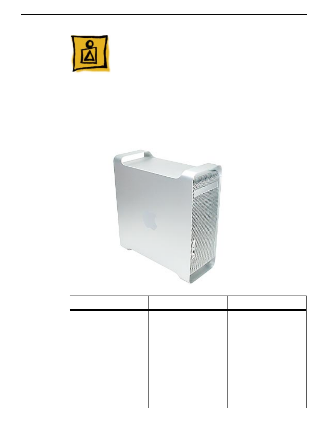
Power Mac G5 is a 64-bit desktop computer powered by the PowerPC G5 processor. It
offers memory expansion up to 8GB,1 GHz front-side bus, and advanced 64-bit
computation, while running existing 32-bit applications natively. The computer also
includes serial ATA hard drives, high-end graphics capabilities, and computer-controlled
cooling based on four independent zones. Standard configurations are listed below.
Overview
1.6 GHz Uni 1.8 GHz Uni 2 GHz Dual
800 MHz frontside bus 900 MHz frontside bus 1 GHz frontside bus
256 MB DDR333 SDRAM,
expandable to 4 GB
80 GB Serial ATA drive 160 GB Serial ATA drive 160 GB Serial ATA drive
SuperDrive SuperDrive SuperDrive
Three PCI slots Three PCI-X slots Three PCI-X slots
NVIDIA GeForce FX 5200
Ultra video card
56K internal modem 56K internal modem 56K internal modem
512 MB DDR400 SDRAM,
expandable to 8 GB
NVIDIA GeForce FX 5200
Ultra video card
512 MB DDR400 SDRAM,
expandable to 8 GB
ATI Radeon 9600 Pro
video card
Power Mac G5 Basics -
1
Page 5
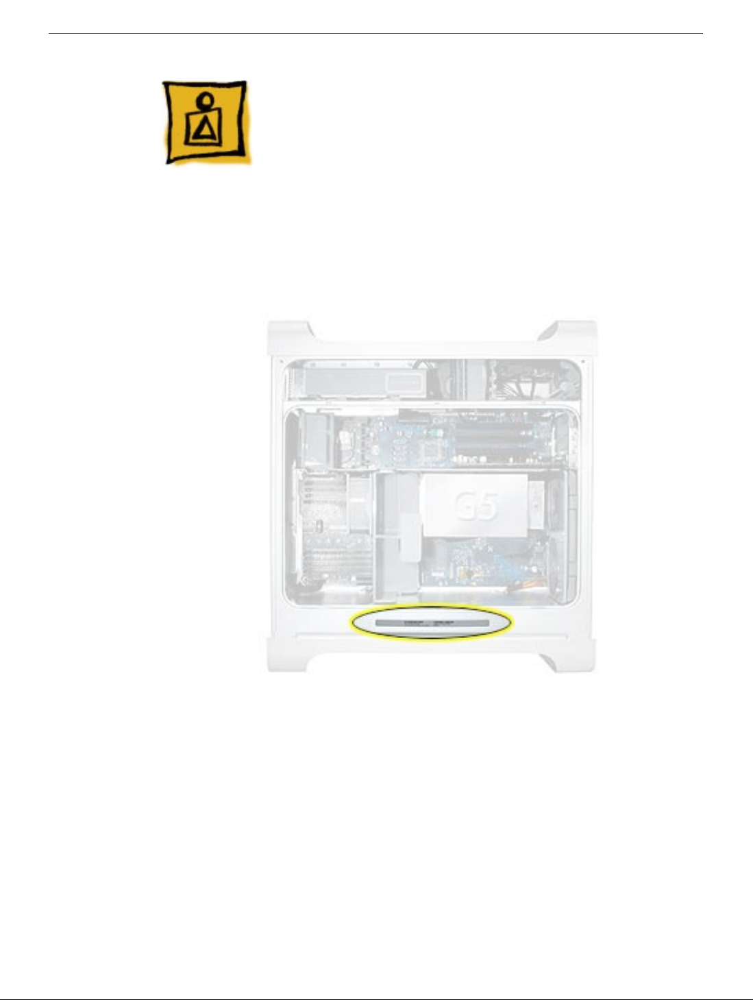
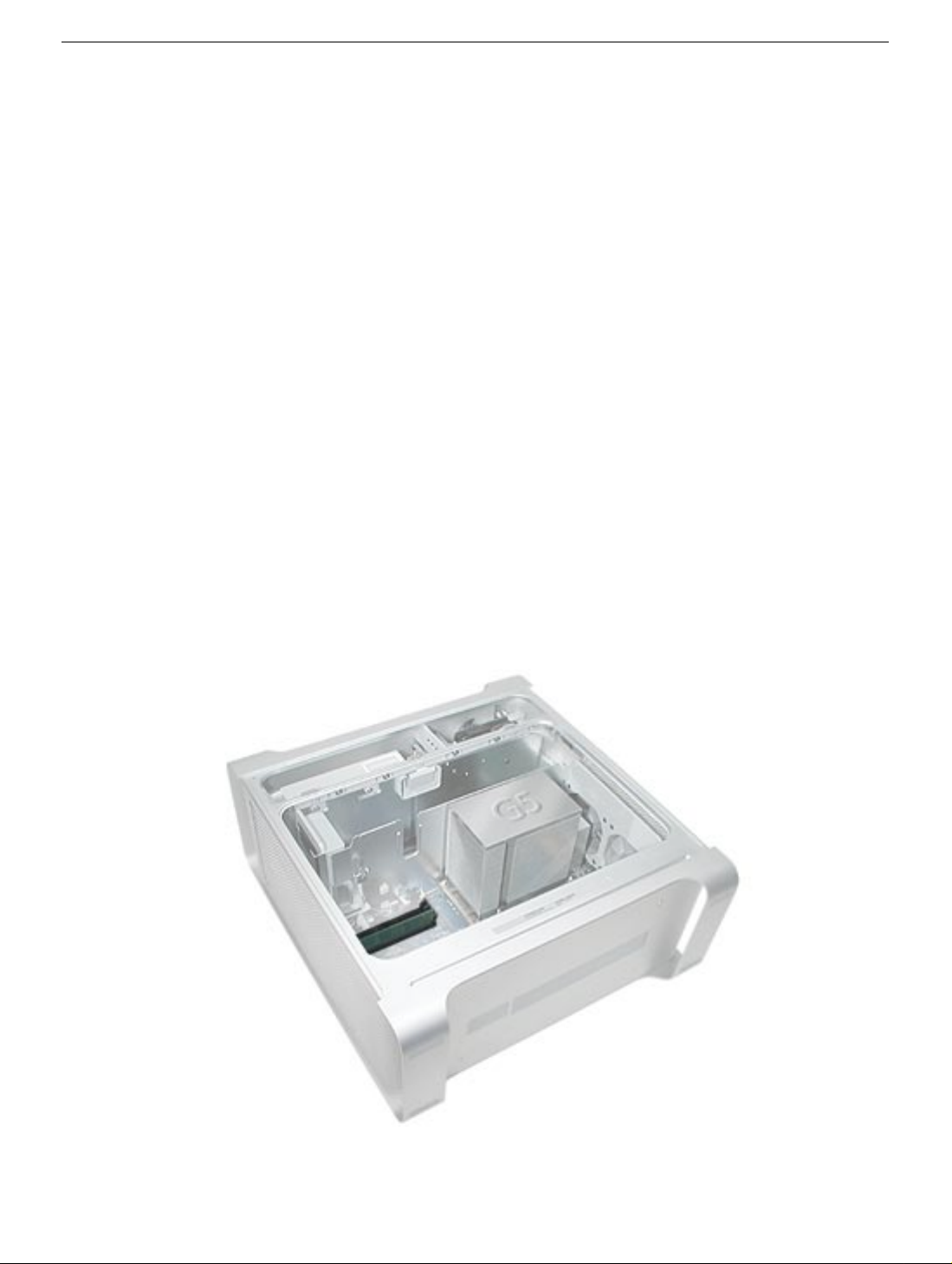
Serial Number Location
To identify a particular model of Power Mac G5, check the computer’s serial number,
which lists the model’s configuration. The serial number is located directly below the air
deflector inside the side access panel.
2 -
Power Mac G5 Basics
Serial Number Location
Page 6

What’s New
Overview
PowerPC G5
processor running at either 1.6, 1.8, or 2.0 GHz, well beyond the speeds of G4 processors.
Serial ATA hard drives
Power Mac G5 offer up to 150 MB/s data throughput. The 7200 rpm drives come in 80,
160, or 250 GB capacity.
PCI-X slots
expansion cards that demand high performance. Both 100 and 133 MHz PCI-X slots are
included in higher-end Pow er Mac G5 computers. For more inf ormation, see the “A GP/PCI
Card” topic in the Take Apart chapter.
8x AGP bus
graphics card. Both NVIDIA and ATI graphics cards are offered for the Power Mac G5.
USB 2.0
accommodates more high speed peripherals.
Digital audio in and out
ports, allowing for optical audio input and output. These ports are in addition to the existing
analog sound input and output ports.
Cooling zones
cooling zones in the Power Mac G5. Each zone is software-controlled by the system to
only cool when necessary, making for a more efficient (and quieter) cooling solution.
— The Power Mac G5 computer incudes the new 64-bit PowerPC G5
— Unlike older parallel drives, the new serial ATA drives in the
—Higher-bandwidth PCI slots allow for greater amounts of data when using
— This bus provides a higher amount of data transfer to and from the
—All USB ports on the Power Mac G5 support the USB 2.0 standard, which
—The Pow er Mac G5 introduces two ne w optical audio (S/PDIF)
— Nine case fans and blowers are logically grouped into four separate
What’s New
Controller chips
chips that use “hyper-transport” technology. This new technology allows chips to talk to
each other much faster than older Macs. The overall bandwidth of the system is also
greatly improved.
ATA/100 bus for optical drives
data much faster.
Interleaved DDR RAM
performance. Different models require either DDR 333 or DDR 400 RAM. DIMMs m ust be
installed in pairs of equal size and kind. For more information, see the “Memory (DIMMs)”
topic in the Take Apart chapter.
— The Power Mac G5 includes Northbridge and Southbridge controller
— This technology allows optical storage to read/write
—The Power Mac G5 requires pairs of DIMMs, which increases
Power Mac G5 Basics -
3
Page 7

DDR Memory
Depending on the model, Power Mac G5 computers have either four or eight Dual Inline
Memory Module (DIMM) slots for Double-Data-Rate (DDR) Synchronous Dynamic
Random-Access Memory (SDRAM) devices. The computers ship with a minimum of 256
MB of RAM, installed as a pair of 128 MB DIMMs in two of the DIMM slots. You can install
additional DIMMs, provided they are installed in pairs of equal size. A diagram marked on
the logic board near the slots illustrates how the pairs must be installed.
4 -
Power Mac G5 Basics
To determine the types of DIMMs to install, refer to the table below:
DIMM Slots DIMM speed Maximum amount
4 (two banks of 2 slots) 333 MHz, PC 2700 up to 4 GB
8 (two banks of 4 slots) 400 MHz, PC 3200 up to 8 GB
In addition, DIMMs must fit these specifications:
• 2.5 volt
• 84-pin module
• Maximum number of memory devices on DDR SDRAM:16
• Nonparity
• No error correcting codes (ECC)
• Unbuffered (registered or buffered DDR SDRAM cannot be used)
What’s New
Page 8

Video
The Power Mac G5 computer comes with a graphics card installed in the AGP 3.0compliant 8x Pro slot.
All graphics cards support dual displays in either extended desktop or video mirroring
mode, and support digital resolutions up to 1920x1200 pixels and analog resolutions up to
1600x1200 pixels.
The display memory on the AGP card is separate from the main memory. The display
memory consists of 64 or 128 MB of DDR devices configured to make a 128-bit data bus.
The display memory cannot be expanded by the user.
The supported graphics cards are shown below:
Graphics Video SDRAM Connectors
NVIDIA GeForce FX 5200 Ultra 64 MB DDR ADC and DVI-I
ATI Radeon 9600 Pro 64 MB DDR ADC and DVI-I
ATI Radeon 9800 Pro (CTO) 128 MB DDR ADC and DVI-I
Fan Controller
The Power Mac G5 system employs advanced thermal management to keep acoustic
noise to a minimum. The system is divided into discrete zones, each with independently
controlled fans bringing in cool air from the front of the enclosure, directing it through ducts
and exhausting it out the rear. Temperature and power consumption are monitored by the
operating system, which communicates with the Fan Control Unit, which in turn controls
and monitors fan operation. Note that if Mac OS X is not booted, thermal management will
not work correctly.
Important:
Diagnostic whenever y ou replace a processor or logic board with a ne w processor or logic
board. You must also run the diagnostic if you re-install the same processor but in a
different connector from the one in which it was originally installed. For more information,
see “Thermal Calibration” in the Troubleshooting chapter.
To ensure proper fan and temperature control, you must run Apple Service
Optical A udio
What’s New
Digital data is transmitted to and from the optical audio I/O using special optical cables.
The 7.5 mm digital optical connectors on the cables, commonly referred to as TOSLink,
are for both input and output and conform to the IEC60874-17 connector standard.
The TOSLink friction-lock type F-05 connectors are available from pro-audio, musician’s
supply, hi-fi, and other retailers.
Power Mac G5 Basics -
5
Page 9

Analog audio signals are converted to digital data internally. All audio is handled digitally
inside the computer, including audio data from the CD or DVD drive and from devices
connected to the USB and FireWire ports. Audio data is converted to analog form for
output to the internal speaker, the headphones, or the analog output port.
Wireless
The Power Mac G5 supports an optional internal Apple Bluetooth module that enables
short-range wireless connections between desktop and laptop computers and a host of
other peripheral devices. Bluetooth support is built into Mac OS X and compliant with
Bluetooth specification v1.1. It operates on a globally available 2.4 GHz frequency band
(ISM band) for worldwide compatibility and has a maximum throughput of 1Mbps.
The Bluetooth technology supports the following profiles:
• synchronization —enables synchronization of devices over Bluetooth
• serial —provides a wireless serial connection to other Bluetooth devices
• dial-up networking (DUN) — enables a mobile phone to act as a modem
• object push —enables the transfer of files between Bluetooth devices
Important:
attached to the Bluetooth port and the external AirPort antenna must be attached to the
AirPort port on the back panel of the Power Mac G5.
For proper range and operation, the external Bluetooth antenna must be
Ports
The following ports are included on the front and back panels of the Power Mac G5. For
illustrations of the port locations, see the “External Views” topic in the Views chapter.
Front
• Power button
• Headphone port
• USB 2.0 port
• FireWire 400 port
Rear
• AirPort antenna port
• Bluetooth antenna port
• Optical audio-out port
• Optical audio-in port
• Audio line-out port
• Audio line-in port
• USB 2.0 ports (two ports)
• FireWire 400 port
• FireWire 800 port
• 10/100/1000Base-T Ethernet port
• Modem port
6 -
Power Mac G5 Basics
What’s New
Page 10

What’s New
Power Mac G5 Basics -
7
Page 11

Service Source
Take Apart
Power Mac G5
© 2003 Apple Computer, Inc. All rights reserved.
Page 12

General Information
Orientation
For most take-apart procedures, it is recommended that you lay the computer on its side
before removing or installing the part. For proper operation, however, Apple recommends
that the unit be run in the upright position. The computer should never be operated on its
side with the access panel facing down.
Tools
The following tools are required to service the computer:
• Long-handled magnetic Phillips screwdriver (10-inch shaft)
• Short-handled magnetic Phillips screwdriver
• Flatblade screwdriver
• Jeweler’s flatblade screwdriver
• Needlenose pliers
• Long-handled hex wrench
• Tape (for temporarily holding cables out of the way)
• Small mirror (for seeing small boards inside the enclosure)
• Soft cloth (for protect removed parts from scratches)
General Information
Power Mac G5 Take Apart -
1
Page 13

Opening the Computer
Tools
No tools are required for this procedure.
Preliminary Steps
1. Shut down the computer.
Warning:
internal components or the components you are installing. Do not open the computer
or attempt to install items inside it while it is on.
2. Wait 5 to 10 minutes to allow the computer’s internal components to cool.
Warning:
You must let the computer cool down before continuing.
3. Unplug all external cables from the computer except the power cord.
4. Touch the metal PCI access covers on the back of the computer to discharge any
static electricity from your body.
Important:
components inside the computer. To avoid generating static electricity, do not walk
around the room until you have finished working and closed the computer.
5. Unplug the power cord.
6. Put on an ESD wrist strap.
Always shut down the computer before opening it to avoid damaging its
After you shut down the system, the internal components can be very hot.
Always discharge static before you touch any parts or install any
2 -
Power Mac G5 Take Apart
Opening the Computer
Page 14
Procedure
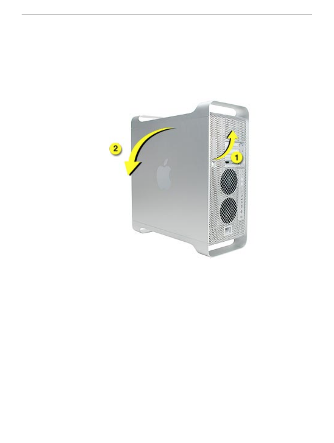
1. Hold the side access panel and lift the latch on the back of the computer.
Warning:
when handling them.
2. Remove the access panel and place it on a flat surface covered by a soft, clean cloth.
The edges of the access panel and the enclosure can be sharp. Be very careful
Replacement Note:
panel. If the latch is down, the access panel will not seat correctly in the enclosure.
Opening the Computer
Make sure the latch is in the up position before replacing the access
Power Mac G5 Take Apart -
3
Page 15
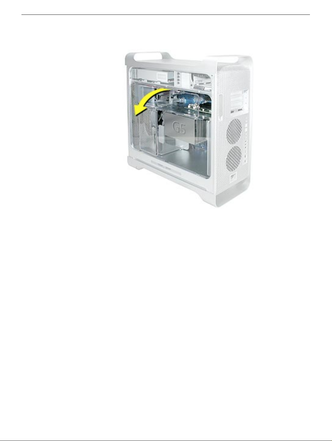
3. Remove the air deflector and place it on a soft, clean cloth.
Replacement Note:
of the deflector into the three slots in the bottom frame of the enclosure. Then swing the
deflector up flush against the top frame of the enclosure.
Important:
the air deflector is not installed, the computer will not function properly.
Make sure you re-install the air deflector before replacing the access panel. If
To replace the air deflector, insert the three tabs on the bottom edge
4 -
Power Mac G5 Take Apart
Opening the Computer
Page 16
Serial ATA Hard Drive
The Power Mac G5 computer can accommodate two serial ATA hard drives in its internal
hard drive bay. In most configurations, a single hard drive occupies the top portion of the
bay. You can install one additional serial ATA hard drive to the empty slot in the bay.
Important:
installing ATA hard drives.
Use the original Apple cables that came with the Power Mac G5 when
Tools
The only tool required for this procedure is a Phillips screwdriver.
Preliminary Steps
Before you begin, open the computer.
Part Location
Serial ATA Hard Drive
Power Mac G5 Take Apart -
5
Page 17
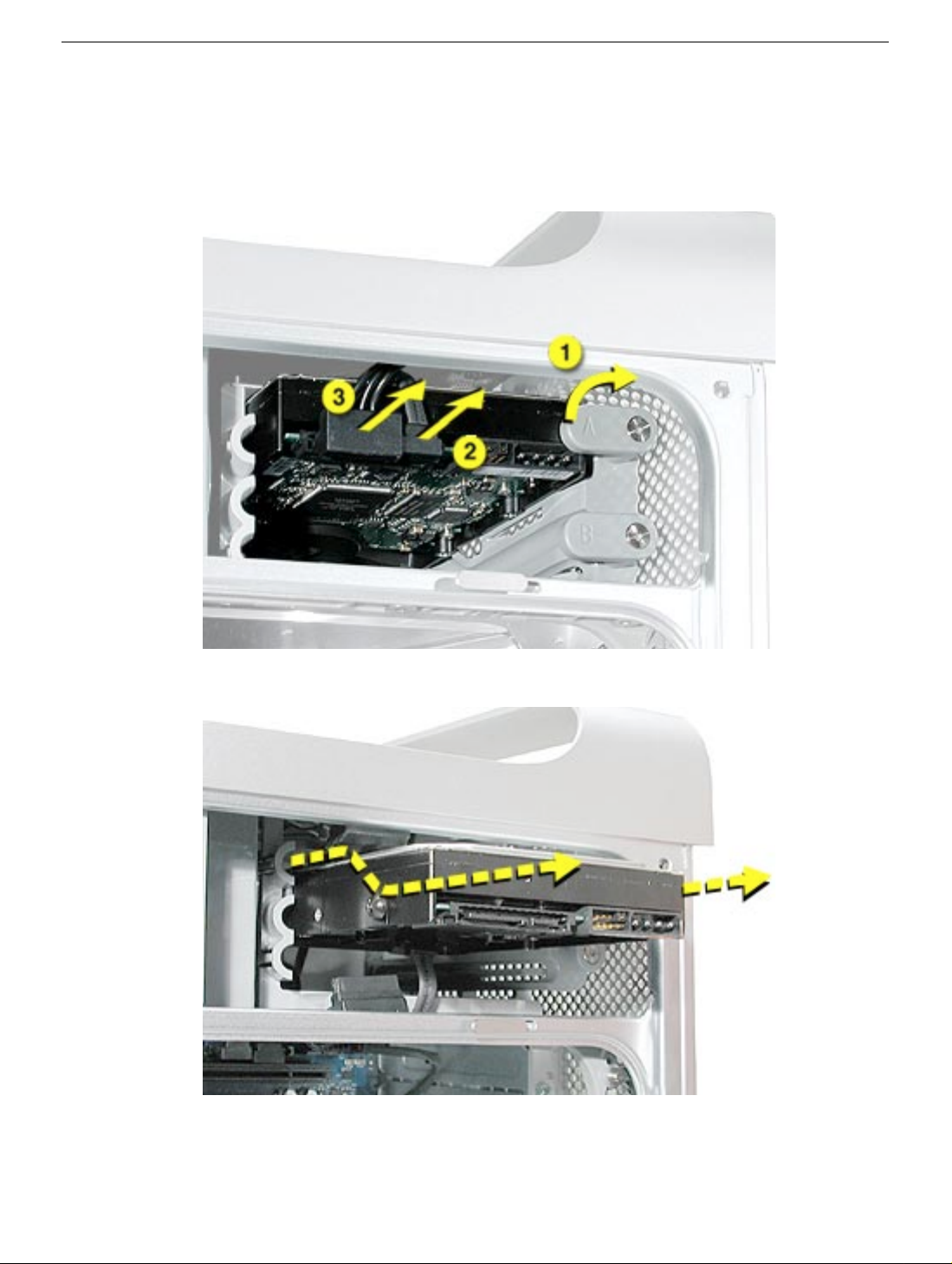
Procedure
1. Release the drive locking latch by rotating it up.
2. Disconnect the drive data cable and power cable from the hard drive.
3. Pull the drive out of the drive bay, being careful not to touch the bottom of the drive.
Important:
hold the drive by its sides. To avoid damaging the replacement drive, take care not to touch
the PCB during installation.
If the printed circuit board (PCB) is exposed on the bottom of the hard drive,
6 -
Power Mac G5 Take Apart
Serial ATA Hard Drive
Page 18
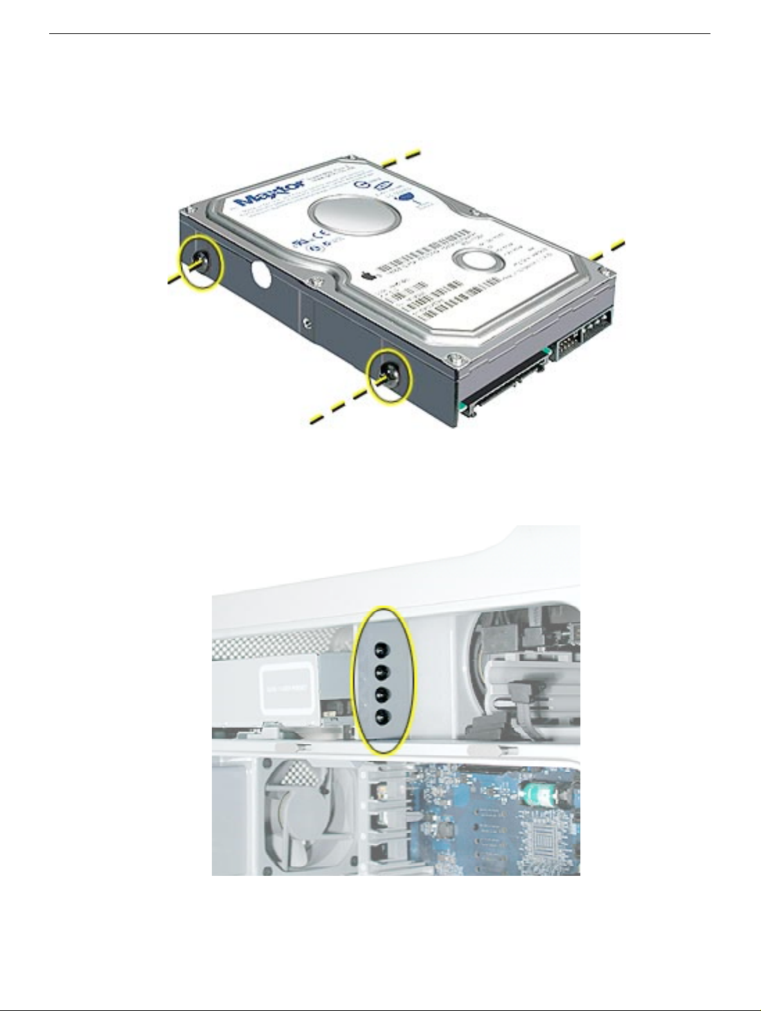
4. If you are replacing the drive with a new drive, transfer the four hard drive guide
screws from the sides of the original drive to the replacement drive.
5. If you are installing an additional drive, remov e the f our guide scre ws from the left side
of the hard drive bay and screw them into the sides of the new drive.
Serial ATA Hard Drive
Power Mac G5 Take Apart -
7
Page 19
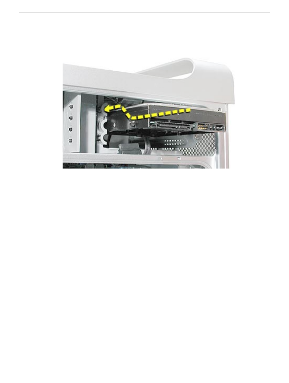
Replacement Note: When replacing the top drive, make sure the guide screws align with
the middle slot of the drive bay, and then gently push the drive into the bay until it snaps
into place in the top position.
When installing a bottom drive, align the guide screws with the bottom slot of the drive ba y
and slide the drive in until it snaps into place.
8 - Power Mac G5 Take Apart
Serial ATA Hard Drive
Page 20
Optical Drive
Important: When installing a replacement optical drive, use the original Apple cab les that
came with the Power Mac G5.
Tools
No tools are required for this procedure.
Preliminary Steps
Before you begin, open the computer.
Part Location
Optical Drive
Power Mac G5 Take Apart - 9
Page 21

Procedure
1. Disconnect the optical drive ribbon cable from the logic board. (The cab le connector is
located under the media shelf that holds the optical drive.)
2. Push the optical drive levers out to release the drive.
10 - Power Mac G5 Take Apart
Optical Drive
Page 22
3. Place the fingers on one hand inside the opening for the optical drive cable and push
the edge of the drive forward. The drive will move part way out of the media shelf.
4. Disconnect the power cable from the drive.
5. Route the drive ribbon cable out through the opening in the media shelf and remove
the drive and ribbon cable from the computer.
Optical Drive
Power Mac G5 Take Apart - 11
Page 23
6. If you are replacing the drive with a new drive , install the standoffs on the bottom of the
new drive.
Note for SuperDrives: Two bags of standoffs are included with each drive. Use the
standoffs from the bag marked with the same manufacturer’s name as printed on the
drive.
Note for Combo Drives: Transfer the standoffs from the original drive to the
replacement drive.
12 - Power Mac G5 Take Apart
Optical Drive
Page 24
7. Disconnect the ribbon cable from the back of the drive, and then carefully pry the
cable from the top of the drive. Transfer the cable to the top of the replacement drive,
and connect the cable to the drive.
Note: Reusable adhesive tape on the underside of the cable attaches the cable to
the drive. When removing the cable from the original drive, be careful to keep the
tape with the cable.
8. Carefully remove the EMI shield from the front of the original drive and transf er it to the
front of the replacement drive.
Replacement Note: Insert the optical drive part way into the optical drive bay, and
connect the power cable to the drive. Then bend down the free end of the ribbon cable,
route it through the opening at the back of the media shelf, and connect the cable to the
logic board.
Optical Drive
Power Mac G5 Take Apart - 13
Page 25
Front Inlet Fan(s)
The front inlet fan assembly consists of one or two f ans in a plastic brac k et. If the computer
is a uniprocessor, the assembly contains a single fan; if the computer is a dual processor,
the assembly contains two fans connected by a single cable.
You must remove the front inlet fan assembly to access many other parts within the
computer. For this access, remove the bracket with the fans attached. You will have to
remove the fans from the bracket only if you are replacing the fans themselves.
Tools
The only tool required for this procedure is needlenose pliers.
Preliminary Steps
Before you begin, open the computer and lay it on its side with the access side facing up.
Part Location
14 - Power Mac G5 Take Apart
Front Inlet Fan(s)
Page 26
Procedure
1. Hold the front inlet fan assembly by the front handle and firmly pull it out of the
computer.
Front Inlet Fan(s)
Power Mac G5 Take Apart - 15
Page 27
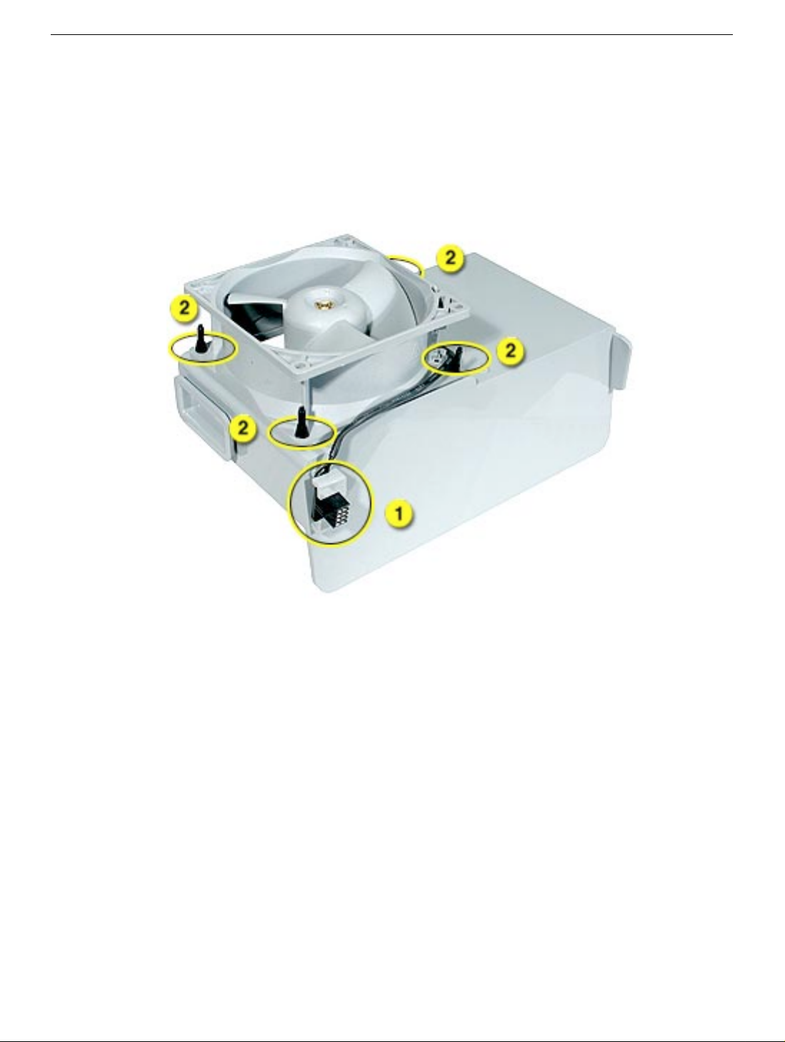
2. If you are replacing the fan(s) in the bracket, do the following:
• Remove the fan cable from the cable guide.
• Using needlenose pliers, pull the fan(s) off the grommet fasteners, and remove the
fan(s) and cable from the bracket.
Important: If you are replacing two fans, be careful that you do not separate the fans
from each other. They are connected by a common cable.
16 - Power Mac G5 Take Apart
Front Inlet Fan(s)
Page 28
Replacement Note: To replace the front inlet fan bracket in the enclosure, align the large
rail on the bracket with the cutout in the PCI divider and press firmly.
Important: Make sure the connector on the fan fully engages the fan connector on the
logic board, or the computer will not operate properly. Gently pull the fan assembly to test
whether it is connected.
Front Inlet Fan(s)
Power Mac G5 Take Apart - 17
Page 29

Memory (DIMMs)
Depending on the model, Power Mac G5 computers have either four or eight Dual Inline
Memory Module (DIMM) slots arranged in two banks. The slots accept Double-Data-Rate
(DDR) Synchronous Dynamic Random-Access Memory (SDRAM) devices.
The computers ship with a minimum of 256 MB of RAM, provided by a pair of 128 MB
DIMMs installed in slot 1 of each DIMM bank. You can add DIMMs, provided they are
installed in pairs of equal size, one per bank, from the center outward. A diagram marked
on the logic board near the DIMM slots illustrates how the pairs must be installed.
To determine the types of DIMMs to install, refer to the table below:
DIMM Slots DIMM speed Maximum amount
4 333 MHz, PC 2700 up to 4 GB
8 400 MHz, PC 3200 up to 8 GB
18 - Power Mac G5 Take Apart
Memory (DIMMs)
Page 30
In addition, DIMMs must fit these specifications:
• 2.5 volt
• 84-pin module
• Maximum number of memory devices on DDR SDRAM:16.
• Nonparity
• No error correcting codes (ECC)
• Unbuffered (registered or buffered DDR SDRAM cannot be used)
Important: Always install DIMMs in pairs of equal size. Memory from older Macintosh
computers is not compatible with the Power Mac G5. Do not use older memory, even if it
fits into the DIMM slots.
Tools
No tools are required for this procedure.
Preliminary Steps
Before you begin, open the computer, lay it on its side with the access side facing up, and
remove the front inlet fan assembly.
Part Location
Memory (DIMMs)
Power Mac G5 Take Apart - 19
Page 31

Procedure
1. Locate the DIMM slots on the logic board.
2. Open the ejectors on the DIMM slot by pushing them out to the sides.
3. Holding the DIMM by both top corners, lift it straight up out of the computer.
Replacement Note: Align the DIMM in the slot and push both ends of the DIMM down
until the tabs are vertical and the ejectors snap into place.
Important: Do not touch the DIMM connectors. Handle the DIMM only by the edges.
20 - Power Mac G5 Take Apart
Memory (DIMMs)
Page 32

AGP/PCI Card
The Pow er Mac G5 computer has four expansion card slots, three of which accommodate
Peripheral Component Interconnect (PCI) cards and one that accepts an advanced
graphics port (AGP) video card. AGP cards and PCI cards have different connectors, so
you cannot insert a PCI card into the AGP slot.
Note: Maximum power consumption for all four expansion slots (the three PCI expansion
cards and the AGP card) should not exceed 90 watts (W).
AGP Slot 1
PCI Slot 2
PCI Slot 3
PCI Slot 4
AGP/PCI Card
AGP Cards
The AGP video card, installed in slot 1, contains the graphics processor unit (GPU) and
provides the computer’s display ports. Slot 1 is designed specifically to accept AGP cards .
This 533-megahertz (MHz) slot accommodates 1.5-volt (V) AGP cards.
PCI Cards
The remaining three expansion slots, labeled 2, 3, and 4, accommodate PCI cards up to
12 inches long. Depending on the Power Mac G5 model, you can install either PCI or
PCI-X cards.
Note: To determine if a Power Mac G5 computer can accommodate PCI-X cards, check
the number of DIMM slots on the logic board. Computers with four DIMM slots have
Power Mac G5 Take Apart - 21
Page 33

33 MHz PCI slots and cannot use PCI-X cards; computers with eight DIMM slots can
accommodate 100 and 133 MHz PCI-X cards. See the chart below.
Card type PCI slot Card speed
PCI* slots 2, 3, and 4 64-bit, 33 MHz
PCI-X slots 2 and 3 64-bit, 100 MHz
slot 4 64-bit, 133 MHz
*The PCI slots can accommodate mixed-voltage (5.0 V, 12 V, or 3.3 V) cards but only at
3.3 V signaling, with 32-bit or 64-bit data widths and a 33 MHz frequency. You can add a
66 MHz card to a 33 MHz PCI slot if the card can operate at the lower 33 MHz rate.
Warning: Do not use PCI cards that function only at 66 MHz in the PCI slots. Damage to
the equipment could result. If y ou are installing an additional 66 MHz PCI card, rather than
replacing an existing PCI card like-f or-lik e , chec k with the card’s manufacturer to see if the
new 66 MHz card also works at 33 MHz.
Tools
The only tool required for this procedure is a Phillips screwdriver.
Preliminary Steps
Before you begin, open the computer and lay it on its side with the access side facing up.
Part Location
22 - Power Mac G5 Take Apart
AGP/PCI Card
Page 34

Procedure
Install an AGP video card in slot 1 only. Install either PCI or PCI-X cards in the slots
labeled 2, 3, and 4.
Warning: When removing or installing a PCI or AGP card, handle it only by the edges. Do
not touch its connectors or any of the components on the card. Lift the card straight out
from the connector to remove it, and insert it straight into the connector to install it. Do not
rock the card from side to side and don’t force the card into the slot. Once the replacement
card is installed, pull on it gently to check that it is properly connected.
1. Remove the screw that mounts the card to the enclosure.
2. If you are removing an AGP card, pull back the small locking clip at the front of the
AGP connector.
3. Holding the card by the top corners, gently pull up the card and remove it from its
expansion slot.
AGP/PCI Card
Replacement Note: Align the card’s connector with the e xpansion slot and press until the
connector is inserted all the way into the slot. If you’re installing a 12-inch card, make sure
the card engages the appropriate slot in the PCI card guide.
• Don’t rock the card from side to side; instead, press the card straight into the slot.
• Don’t force the card. If you meet a lot of resistance, pull the card out. Check the
connector and the slot for damage or obstructions, then try inserting the card again.
• Pull the card gently to see if it is properly connected. If it resists and stays in place,
and if its gold connectors are barely visible, the card is connected.
Power Mac G5 Take Apart - 23
Page 35

AirPort Extreme Card
Only the AirPort Extreme Card may be installed in the P o w er Mac G5. Older AirPort Cards
do not work in this computer.
Tools
No tools are required for this procedure.
Preliminary Steps
Before you begin, open the computer and lay it on its side with the access side facing up.
Part Location
24 - Power Mac G5 Take Apart
AirPort Extreme Card
Page 36

Procedure
1. Carefully disconnect the antenna cable from the end of the AirPort Extreme Card.
2. Pull the card straight back out of the enclosure.
Replacement Note: Position the AirPort Extreme Card with the ID numbers and barcode
facing up and insert the card into the AirPort Extreme Card connector.
Important: Be sure to reconnect the antenna cable to the card.
AirPort Extreme Card
Power Mac G5 Take Apart - 25
Page 37

Battery
Tools
No tools are required for this procedure. You may, however, find a flat-blade screwdriver
useful in removing the battery from its holder.
Preliminary Steps
Before you begin, open the computer and lay it on its side with the access side facing up.
If a PCI card is installed in the slot next to the battery, remove the card.
Part Location
26 - Power Mac G5 Take Apart
Battery
Page 38

Procedure
1. If necessary, carefully spread the tabs holding the battery.
2. Remove the battery from its holder, noting the orientation of the battery’s positive end.
(A plus sign is marked on or near the battery holder.)
Battery
Replacement Note: Insert the new battery in the holder, making sure the battery’s
positive symbol aligns with the positive symbol on or near the holder.
Warning: Installing the battery incorrectly may cause an explosion. Be sure the battery’s
positive and negative poles are correctly oriented in the holder. Use only the same type of
battery or an equivalent recommended by the manufacturer of the original.
Important: Batteries contain chemicals, some of which may be harmful to the
environment. Please dispose of used batteries according to y our local en vironmental laws
and guidelines.
Power Mac G5 Take Apart - 27
Page 39

Rear Exhaust Fan(s)
Tools
The following tools required for this procedure:
• Phillips screwdriver
• Needlenose pliers
• Flatblade screwdriver
Preliminary Steps
Before you begin, open the computer, lay it on its side with the access side facing up, and
remove all AGP and PCI cards.
Part Location
28 - Power Mac G5 Take Apart
Rear Exhaust Fan(s)
Page 40

Procedure
1. Disconnect the fan cable from the logic board.
Note: Press the cable connector up toward the media shelf when disconnecting the
cable.
2. Press down on the two tabs on the top of the fan bracket to release the two latches.
3. Lift the fan bracket and fans out of the enclosure.
Rear Exhaust Fan(s)
Power Mac G5 Take Apart - 29
Page 41

4. If you are replacing the fans, use needlenose pliers to pull each fan off the four
grommets that mount it to the bracket, and remove the fans and cable from the
bracket.
Replacement Note: When reinstalling the f an br ack et in the enclosure , make sure the tw o
tabs on the bottom of the bracket engage with the slots in the enclosure’s fan guide.
30 - Power Mac G5 Take Apart
Rear Exhaust Fan(s)
Page 42

Then rotate the fan back flush with the rear panel, making sure the two latches on the top
of the bracket engage with the two slots on the top of the fan guide.
Replacement Note: Using a flatblade screwdriver, tuck the fan cable under the edge of
the logic board.
Rear Exhaust Fan(s)
Power Mac G5 Take Apart - 31
Page 43

Speaker/Fan Assembly
Tools
The only tools required for this procedure are a Phillips screwdriver and needlenose pliers .
Preliminary Steps
Before you begin, open the computer and lay it on its side with the access side facing up.
Part Location
32 - Power Mac G5 Take Apart
Speaker/Fan Assembly
Page 44

Procedure
1. Disconnect the speaker and fan cables from the logic board.
2. Lift the speaker/fan assembly straight up and remove it from the enclosure.
Important: Be careful that the fan and speaker cables do not catch on the PCI
divider as you lift the assembly.
3. If you are replacing the speaker , remo v e the two scre ws and remo v e the speak er from
Speaker/Fan Assembly
the speaker/fan bracket.
Power Mac G5 Take Apart - 33
Page 45

4. If you are replacing the fan, use needlenose pliers to pull the fan off the four grommet
fasteners. Then remove the fan from the bracket.
Replacement Note: When reinstalling the speaker/fan bracket in the enclosure, make
sure the large tab on the side of bracket engages with the channel in the PCI divider.
34 - Power Mac G5 Take Apart
Speaker/Fan Assembly
Page 46

Modem Board
Tools
The only tool required for this procedure is a Phillips screwdriver.
Preliminary Steps
Before you begin, open the computer, lay it on its side with the access side facing up, and
remove the speaker/fan assembly.
Part Location
Modem Board
Power Mac G5 Take Apart - 35
Page 47

Procedure
1. Remove the two screws that secure the modem board.
2. Lift the board slightly and disconnect the modem filter cable from the modem board.
3. Remove the modem from the enclosure.
Important: Be sure to reconnect the modem filter cable before reinstalling the modem.
36 - Power Mac G5 Take Apart
Modem Board
Page 48

Bluetooth Card
Tools
The only tool required for this procedure is a Phillips screwdriver.
Preliminary Steps
Before you begin, open the computer, lay it on its side with the access side facing up, and
remove the speaker/fan assembly.
Part Location
Bluetooth Card
Power Mac G5 Take Apart - 37
Page 49

Procedure
1. Remove the two Bluetooth mouning screws.
2. Lift the Bluetooth card straight up a short distance to disconnect it from the logic
board. Then turn the card over, and disconnect the Bluetooth antenna cable from the
underside of the card.
Replacement Note: Be very careful connecting the antenna cable to the Bluetooth card.
The connector is fragile and can easily be bent.
38 - Power Mac G5 Take Apart
Bluetooth Card
Page 50

Processor
Tools
The only tool required for this procedure is a long-handled Phillips screwdriver.
Preliminary Steps
Before you begin, open the computer, lay it on its side with the access side facing up, and
remove the front inlet fan assembly.
Part Location
Processor
Power Mac G5 Take Apart - 39
Page 51

Procedure
1. Remove the metal G5 cap from the top of the heatsink.
Note: The cap is held in place by two sets of small plastic latches on the underside of
the cap. To release the latches, place both index fingers under the edge of the cap
near the “G” and press in on the first set of latches. Then release the second set of
latches under the opposite edge of the cap and lift the cap off the heatsink.
40 - Power Mac G5 Take Apart
Processor
Page 52

2. Using a long-handled Phillips screwdriver, remove the four processor mounting
screws.
3. Lift the heatsink and processor straight up out of the computer.
Warning: The heatsink and processor are a unit. Never separate the heatsink from
the processor, or you will damage the processor and void the warranty.
4. Repeat steps 1–3 for the second processor, if necessary.
Processor
Power Mac G5 Take Apart - 41
Page 53

Replacement Note: If you are replacing the processor with a new processor, do the
following:
• When removing the new processor from its packaging, be careful to lift the processor
straight up out of the box. Tilting the processor could damage the heatsink seal.
• Before installing the processor, remove the cap over the processor connector.
Warning: Do not remove the clear plastic strip on the bottom of the processor. Removing
the plastic could cause a short in the logic board.
Note: When installing the processor, place the first two scre ws diagonally from each other
and tighten part way. Replace the other two screws and tighten part way. Then tighten all
screws again until they are fully secured.
Important: Whenever you replace a processor with a new processor, you must run Apple
Service Diagnostic (once the computer is reassembled). You must also run the diagnostic
if you re-install the same processor but in a different connector from the one in which it
was originally installed. Apple Service Diagnostic for Power Mac G5 is available as a
download from the Disc Images section of the Apple Service Source website. For more
information, see “Thermal Calibration” in the Troubleshooting chapter.
42 - Power Mac G5 Take Apart
Processor
Page 54

Modem Filter Board and Cables
Tools
The only tool required for this procedure is a Phillips screwdriver.
Preliminary Steps
Before you begin, open the computer, lay it on its side with the access side facing up, and
remove the following:
• Front inlet fan assembly
• Processor(s)
• All AGP and PCI cards
• Rear exhaust fan assembly
• Speaker/fan assembly
• Modem
Part Location
Modem Filter Board and Cables
Power Mac G5 Take Apart - 43
Page 55

Procedure
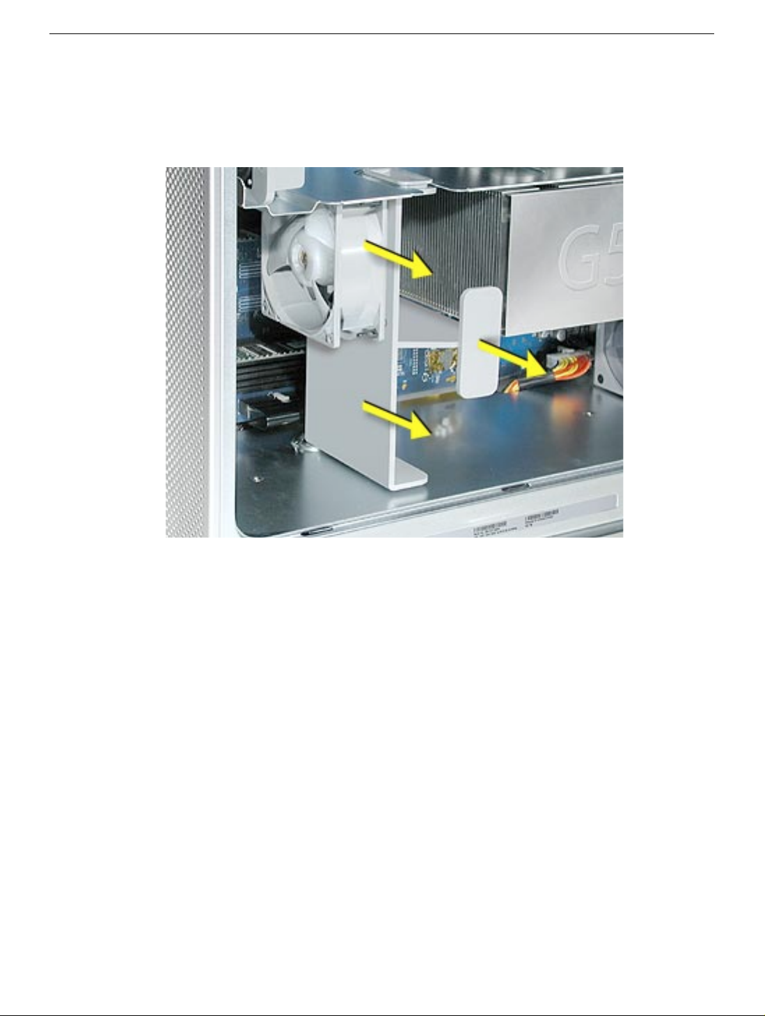
1. Route the modem filter board cable out through the opening in the PCI divider.
2. Disengage the cable from the cable guides on the PCI divider.
3. Disconnect the power cable next to the modem filter board.
4. Remove the mounting screw on the modem filter board cap.
44 - Power Mac G5 Take Apart
Modem Filter Board and Cables
Page 56

5. Slide the modem filter board back to disengage it from its mounting bracket, and
remove the board and cable from the logic board.
Replacement Note: When re-installing the modem filter board in its mounting bracket, be
careful to engage the slots in the board with the edges of the bracket.
Modem Filter Board and Cables
Power Mac G5 Take Apart - 45
Page 57

Replacement Note: Make sure the modem filter cable routes out through the opening in
the side of the modem filter cap before securing the cap to the modem filter board.
Replacement Note: Be careful when rerouting the modem filter cable that it routes under
the black connector for the front inlet fan and out through the correct opening in the PCI
divider. Make sure the cable is in place behind all cable guides.
46 - Power Mac G5 Take Apart
Modem Filter Board and Cables
Page 58

Antenna Board and Cables
Tools
The only tool required for this procedure is a Phillips screwdriver.
Preliminary Steps
Before you begin, open the computer, lay it on its side with the access side facing up, and
remove the following:
• Front inlet fan assembly
• Upper processor
• All AGP and PCI cards
• Rear exhaust fan assembly
Part Location
Antenna Board and Cables
Power Mac G5 Take Apart - 47
Page 59

Procedure
1. Disconnect the black antenna cable from the AirPort Extreme Card (if installed).
2. Disconnect the gray antenna cable from the Bluetooth card (if installed).
3. Bend the antenna board shield back far enough so that you can access the two
antenna board mounting screws, and remove the screws.
48 - Power Mac G5 Take Apart
Antenna Board and Cables
Page 60

4. Remove the Bluetooth cable (gray) and AirPort cable (black) from the cable guides
and remove the antenna board and cables from the logic board.
Replacement Note: Be careful when rerouting the two antenna cables that they route
under the black connector for the front inlet fan. Make sure that the cables are in place
behind all cable guides.
Antenna Board and Cables
Power Mac G5 Take Apart - 49
Page 61

Front Panel Board Cable
Tools
No tools are required for this procedure.
Preliminary Steps
Before you begin, open the computer and lay it on its side with the access side facing up.
Part Location
50 - Power Mac G5 Take Apart
Front Panel Board Cable
Page 62

Procedure
1. Remove the two black plastic caps that cover the front panel board cable connectors.
Note: The caps fit tightly over the connectors. To remove them, rock the caps gently
forward and backward as you lift up.
2. Disconnect the cable from the logic board.
3. Disconnect the other end of the cable from the front panel board and remove the cab le
from the enclosure.
Front Panel Board Cable
Power Mac G5 Take Apart - 51
Page 63

PCI Card Guide
Tools
The only tool required for this procedure is a Phillips screwdriver.
Preliminary Steps
Before you begin, open the computer and lay it on its side with the access side facing up.
Part Location
52 - Power Mac G5 Take Apart
PCI Card Guide
Page 64

Procedure
1. Remove the two screws that mount the PCI card guide to the logic board.
2. Slide the card guide up to release the two latches from the PCI divider, and remove
the card guide from the enclosure.
PCI Card Guide
Power Mac G5 Take Apart - 53
Page 65

Power Supply
Tools
The only tool required for this procedure is a short-handled Phillips screwdriver.
Preliminary Steps
Before you begin, open the computer, lay it on its side with the access side facing up, and
remove the following:
• Front inlet fan assembly
• Processor(s)
• All AGP and PCI cards
• Rear exhaust fan assembly
• Front panel board cable
• Memory DIMM if it is in slot next to the power supply cable
Part Location
54 - Power Mac G5 Take Apart
Power Supply
Page 66

Procedure
1. Remove the black plastic caps covering the two power supply cable connectors.
Note: The caps fit tightly over the connectors. To remove them, rock the caps gently
forward and backward as you lift up.
2. Press in on the release latch on the first power supply cable connector and disconnect
the cable from the logic board. Repeat for the other power supply cable.
3. Remove the two scre ws that secure the power supply top co v er , and remo ve the co v er
from the enclosure.
Warning: Whenever the power supply cover is removed, be very careful not to drop
any screws into the power supply. Doing so could short out the unit.
Power Supply
Power Mac G5 Take Apart - 55
Page 67

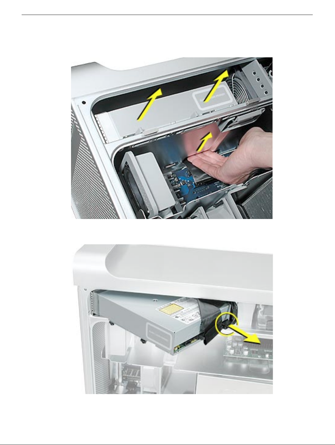
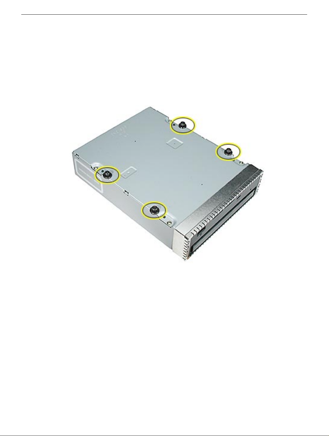
4. Remove the four power supply mounting screws on the bottom of the enclosure.
5. Push in on the power receptacle, and slide the power supply toward the front of the
computer.
6. Tilt the power supply a short distance out of the bottom of the enclosure.
56 - Power Mac G5 Take Apart
Power Supply
Page 68

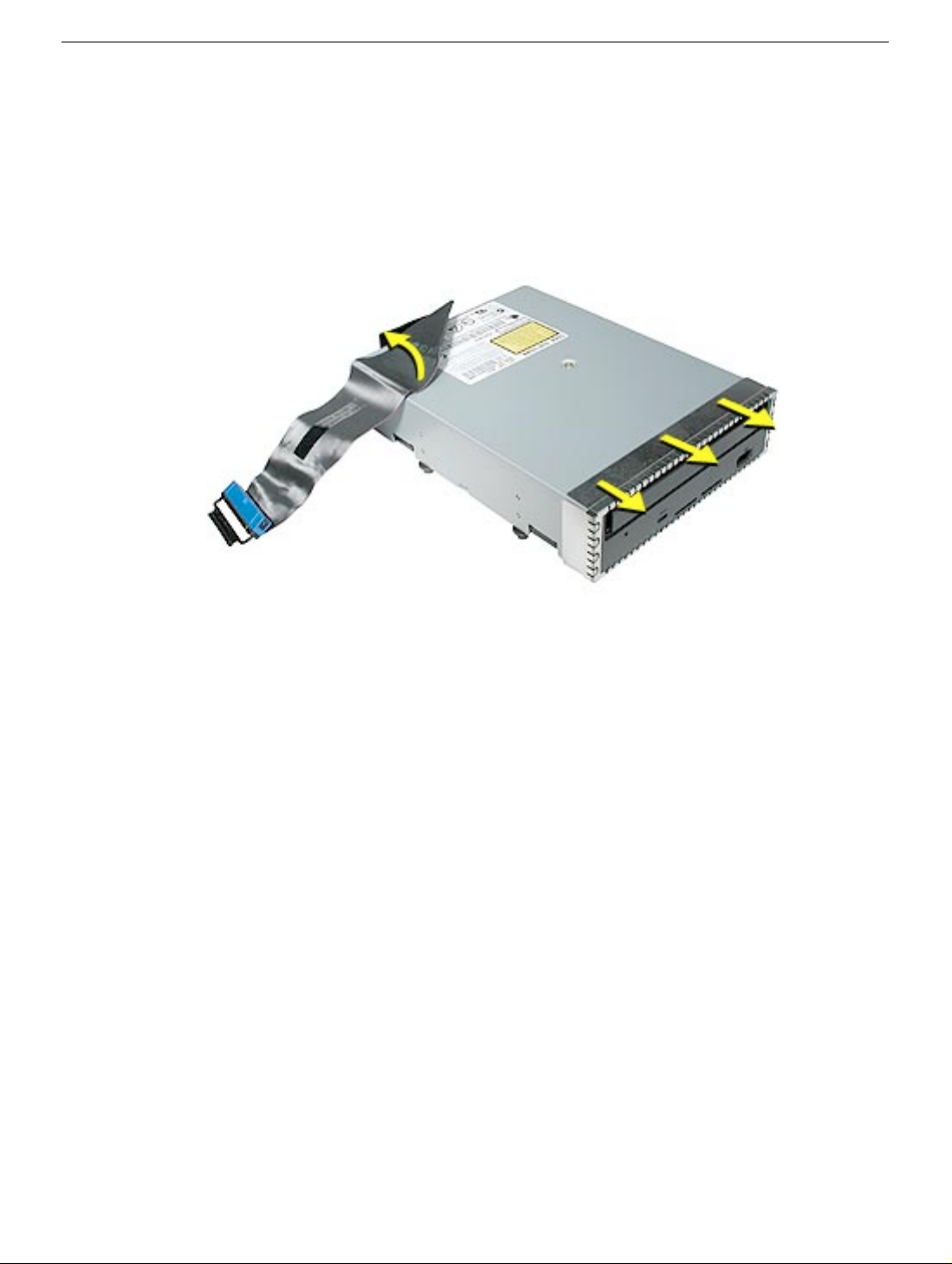
7. Disconnect the power harness cable from the power supply.
8. Remove the power supply from the enclosure.
Replacement Note: After reconnecting the power supply to the power harness cable,
slightly lift the cable so that it does not become wedged under the power supply, and lower
the power supply into the enclosure. Rotate the power supply back flush with the
enclosure bottom until it snaps into place. Then slide the power supply toward the back of
the computer, making sure the pow er receptacle aligns with the opening in the bac k panel.
Power Supply
Power Mac G5 Take Apart - 57
Page 69

Logic Board
Tools
The only tools required for this procedure are a Phillips screwdriver and a hex wrench.
Preliminary Steps
Before you begin, open the computer, lay it on its side with the access side facing up, and
remove the following:
• Front inlet fan assembly
• Processor(s)
• All AGP and PCI cards
• Rear exhaust fan assembly
• Speaker/fan assembly
• Front panel board cable
• Power supply
Part Location
58 - Power Mac G5 Take Apart
Logic Board
Page 70

Procedure
1. Remove the two screws that secure the PCI card guide.
2. Disconnect the six cables from the top of the logic board.
3. Using a hex wrench, remove the four standoffs for the upper processor. Using a
Phillips screwdriver, remove the remaining processor standoff (marked by a square in
the illustration below). Repeat the procedure for a second processor, if installed.
4. Remove the five screws that secure the logic board.
Logic Board
Power Mac G5 Take Apart - 59
Page 71

5. Carefully tilt the logic board up and maneuver it out of the enclosure, making sure the
ports clear the enclosure openings.
Note: Perform the following procedures only if you are replacing the logic board with a
new logic board.
6. Remove the following from the original logic board (see individual procedures in this
chapter for detailed steps):
• Memory DIMMs
• AirPort Extreme Card (if installed)
• Bluetooth card (if installed)
• Modem (if installed)
• Modem filter board and cables
• Antenna board and cables
7. Disconnect the thermistor from the logic board.
60 - Power Mac G5 Take Apart
Logic Board
Page 72

8. Disconnect the front inlet fan cable from the logic board.
9. Remove the three PCI divider mounting screws and remo v e the divider (with PCI card
guide and thermistor attached) from the logic board.
10. Position the PCI divider on the replacement logic board and install the three mounting
screws.
Logic Board
11. Connect the thermistor and front inlet fan cable to the logic board.
Power Mac G5 Take Apart - 61
Page 73

12. Install the modem filter board and cable on the logic board.
13. Install the antenna board and cables on the logic board.
Note: Be careful when rerouting the two antenna cables and the modem filter cable
that they route under the black connector for the front inlet fan. Make sure that the
cables are in place behind all cable guides and that the modem filter cable routes out
through the correct opening in the PCI divider.
14. Connect the modem filter cable to the modem and install the modem on the logic
board.
15. Install the AirPort Extreme Card and Bluetooth card on the logic board and connect
their cables to the cards.
16. Install the memory DIMMs on the logic board.
62 - Power Mac G5 Take Apart
Logic Board
Page 74

17. Transfer the port EMI shield from the original logic board to the replacement logic
board, making sure the shield is fully seated on the ports.
Logic Board
Power Mac G5 Take Apart - 63
Page 75

Replacement Procedure
1. Temporarily tape the top six cables to the media shelf so that they are out of the way.
2. Angle the logic board into the enclosure so that the port edge goes in first.
3. Position the logic board on the three guide pins, aligning the ports with the openings in
the enclosure.
4. Slide the board toward the rear of the computer so that the logic board locks onto the
guide pins and the ports are fully seated in the back panel openings.
64 - Power Mac G5 Take Apart
Logic Board
Page 76

5. Replace the logic board screws and standoffs.
6. Replace the two PCI card guide screws.
7. Connect the six cables at the top of the logic board to the board.
8. Replace the power supply and reconnect all power supply cables to the logic board.
9. Replace the front panel board cable.
10. Replace the speaker/fan assembly and reconnect its cables to the logic board.
11. Replace the rear exhaust fan assembly and reconnect its cable to the logic board.
12. Replace all AGP and PCI cards.
13. Replace the processor(s).
14. Replace the front inlet fan assembly.
Important: Whenever you replace a logic board with a new logic board, you must run
Apple Service Diagnostic (once the computer is reassembled). Apple Service Diagnostic
for Power Mac G5 is available as a download from the Disc Images section of the Apple
Service Source website. For more information, see “Thermal Calibration” in the
Troubleshooting chapter.
Logic Board
Power Mac G5 Take Apart - 65
Page 77

PCI Divider
Tools
The only tools required for this procedure are a Phillips screwdriver and hex wrench.
Preliminary Steps
Before you begin, open the computer, lay it on its side with the access side facing up, and
remove the following:
• Front inlet fan assembly
• Processor(s)
• All AGP and PCI cards
• Rear exhaust fan assembly
• Speaker/fan assembly
• Front panel board cable
• Power supply
• Logic board
Part Location
66 - Power Mac G5 Take Apart
PCI Divider
Page 78

Procedure
1. Disconnect the front inlet fan cable from the logic board.
2. Remove the thermistor from the cable guide on the end of the PCI divider.
PCI Divider
Power Mac G5 Take Apart - 67
Page 79

3. Remove the modem filter board cable, Bluetooth cable, and AirPort cable from the
cable guides on the PCI divider.
Replacement Note: Be careful when rerouting the two antenna cables that they route
under the black connector for the front inlet fan. Make sure that the cables are in place
behind all cable guides.
4. Turn the logic board over so that bottom of the board faces up. Remove the three
screws that secure the PCI divider, and remove the divider from the logic board.
68 - Power Mac G5 Take Apart
PCI Divider
Page 80

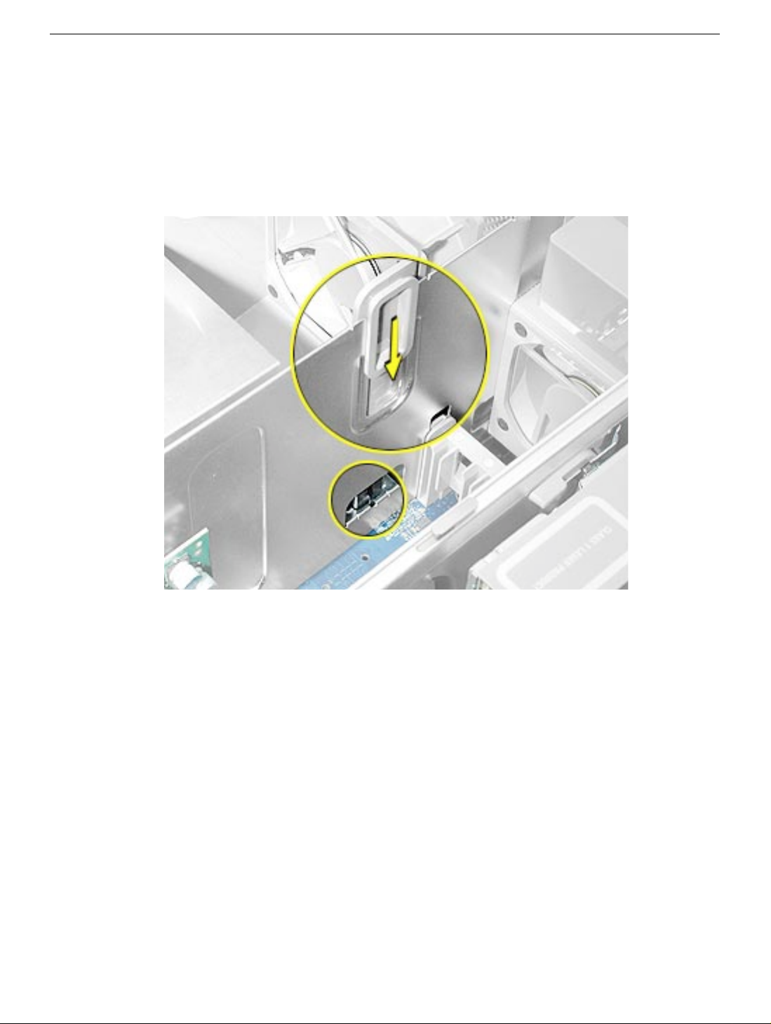
5. Compress the two latches on the sides of the front inlet fan cable connector, press the
connector down through the opening in the PCI divider, and remo ve the cab le from the
divider.
PCI Divider
Power Mac G5 Take Apart - 69
Page 81

Thermistor Cable
Tools
The only tools required for this procedure are a Phillips screwdriver and hex wrench.
Preliminary Steps
Before you begin, open the computer, lay it on its side with the access side facing up, and
remove the following:
• Front inlet fan assembly
• Processor(s)
• All AGP and PCI cards
• Rear exhaust fan assembly
• Speaker/fan assembly
• Front panel board cable
• Power supply
• Logic board
Part Location
70 - Power Mac G5 Take Apart
Thermistor Cable
Page 82

Procedure
1. Disconnect the thermistor cable from the logic board.
2. Remove the thermistor cable from the guide on the PCI divider.
Thermistor Cable
Power Mac G5 Take Apart - 71
Page 83

Front Inlet Fan Cable
Tools
The only tools required for this procedure are a Phillips screwdriver and hex wrench.
Preliminary Steps
Before you begin, open the computer, lay it on its side with the access side facing up, and
remove the following:
• Front inlet fan assembly
• Processor(s)
• All AGP and PCI cards
• Rear exhaust fan assembly
• Speaker/fan assembly
• Front panel board cable
• Power supply
• Logic board
• PCI divider
Part Location
72 - Power Mac G5 Take Apart
Front Inlet Fan Cable
Page 84

Procedure
1. Compress the two latches on the sides of the fan cable connector, and press the
connector down through the opening in the PCI divider.
2. Remove the cable from the PCI divider.
Front Inlet Fan Cable
Power Mac G5 Take Apart - 73
Page 85

Front Panel Board
Tools
The only tools required for this procedure are a jeweler’s flatblade screwdriver, Phillips
screwdriver, and hex wrench.
Preliminary Steps
Before you begin, open the computer, lay it on its side with the access side facing up, and
remove the following:
• Front inlet fan assembly
• Processor(s)
• All AGP and PCI cards
• Rear exhaust fan assembly
• Speaker/fan assembly
• Front panel board cable
• Power supply
• Logic board
Part Location
74 - Power Mac G5 Take Apart
Front Panel Board
Page 86

Procedure
1. Using a jeweler’s flatblade screwdriver, pry up the metal cap covering the front panel
board EMI shield.
2. Using a Phillips screwdriver, remove the two front panel board mounting screws.
Front Panel Board
Power Mac G5 Take Apart - 75
Page 87

3. Carefully pull the board a short distance out of its EMI shield, and disconnect the
power button cable from the board.
4. Remove the board and shield from the enclosure.
Replacement Procedure
1. If you are replacing the front panel board with a new front panel board, do the
following:
• Peel the backing off the mylar insulation for the EMI shield, and apply the mylar to
the side of the shield, as shown.
76 - Power Mac G5 Take Apart
Front Panel Board
Page 88

• Peel the backing off the EMI shield gasket and apply the gasket to the bottom of
the shield, making sure the openings in the gasket align with the shield openings.
2. Thread the power button cable through the opening in the EMI shield and connect the
cable to the front panel board.
3. Insert the front panel board into the EMI shield, making sure the ports are fully seated
in the openings in the shield.
4. Install the front panel board and EMI shield on the inside front of the enclosure and
replace the two mounting screws.
Front Panel Board
5. Install the metal cap on the EMI shield.
Power Mac G5 Take Apart - 77
Page 89

Service Source
Troubleshooting
Power Mac G5
© 2003 Apple Computer, Inc. All rights reserved.
Page 90

General Information
DDR Memory
In the Power Mac G5, DIMMs must always be installed in pairs of equal size and speed.
Use PC2700 DDR-SDRAM for 4-DIMM-slot computers and PC3200 DDR-SDRAM for
8-DIMM-slot computers. Memory from older Macintosh computers is not compatible. Do
not try to install non-DDR memory as it will not physically fit in the DIMM slots and could
damage the logic board.
Results of Mixing PC2100, PC2700, and PC3200 RAM
The table below describes what happens if you install PC2100, PC2700, or PC3200
memory in either a 4-DIMM-slot or 8-DIMM-slot Power Mac G5 computer.
Four-DIMM-Slot Systems
When only PC2100 DIMMs are
installed
When a mix of PC2100, PC2700, or
PC 3200 DIMMs is installed
When only PC3200 DIMMs are
installed in the slots
When no memory is installed The computer does not make a normal startup
Eight-DIMM-Slot Systems
When only PC2100 DIMMs are
installed
When a mix of PC2100, PC2700, or
PC 3200 DIMMs is installed
The computer makes three single tones
instead of the startup sound. The LED on the
front of the computer flashes three times, and
the computer does not startup.
The computer starts up normally, but neither
the computer nor Apple System Profiler
recognizes the PC2100 memory.
The computer starts up normally and behaves
as though PC2700 DIMMs are installed.
sound. Instead, there is a single tone, and the
computer’s front LED flashes continuously.
The computer makes three single tones
instead of the startup sound. The LED on the
front of the computer flashes three times, and
the computer does not startup.
The computer starts up normally, but neither
the computer nor Apple System Profiler
recognizes the PC2100 memory.
General Information
When no memory is installed The computer does not make a normal startup
sound. Instead, there is a single tone, and the
computer’s front LED flashes continuously.
Power Mac G5 Troubleshooting - 1
Page 91

PCI and AGP Cards
The Pow er Mac G5 computer has four expansion card slots, three of which accommodate
Peripheral Component Interconnect (PCI) cards and one that accepts an advanced
graphics port (AGP) video card. AGP cards and PCI cards have different connectors, so
you cannot insert a PCI card into the AGP slot.
AGP Slot 1
PCI Slot 2
PCI Slot 3
PCI Slot 4
Note: Maximum power consumption for all four expansion slots (the three PCI expansion
cards and the AGP card) should not exceed 90 watts (W).
AGP Cards
The AGP video card, installed in slot 1, contains the graphics processor unit (GPU) and
provides the computer’s display ports. Slot 1 is designed specifically to accept AGP cards .
This 533-megahertz (MHz) slot accommodates 1.5-volt (V) AGP cards.
PCI Cards
The remaining three expansion slots, labeled 2, 3, and 4, accommodate PCI cards up to
12 inches long. Depending on the Power Mac G5 model, you can install either PCI or
PCI-X cards.
Note: To determine if a Power Mac G5 computer can accommodate PCI-X cards, check
the number of DIMM slots on the logic board. Computers with four DIMM slots have
33 MHz PCI slots and cannot use PCI-X cards; computers with eight DIMM slots can
accommodate 100 and 133 MHz PCI-X cards. See the chart below.
Card type PCI slot Card speed
PCI* slots 2, 3, and 4 64-bit, 33 MHz
PCI-X slots 2 and 3 64-bit, 100 MHz
slot 4 64-bit, 133 MHz
2 - Power Mac G5 Troubleshooting
General Information
Page 92

*The PCI slots can accommodate mixed-voltage (5.0 V, 12 V, or 3.3 V) cards but only at
3.3 V signaling, with 32-bit or 64-bit data widths and a 33 MHz frequency. You can add a
66 MHz card to a 33 MHz PCI slot if the card can operate at the lower 33 MHz rate.
Warning: Installing PCI cards that function only at 66 MHz could damage the computer.
However, cards that run at both 66 MHz and 33 MHz may be installed. Check with the
card’s manufacturer to see if a 66 MHz card also works at 33 MHz.
Thermal Calibration
To ensure proper fan and temperature control in the Power Mac G5, you must run Apple
Service Diagnostic whenever you replace a processor or logic board with a new processor
or logic board. You must also run the diagnostic if you re-install the same processor but in
a different connector from the one in which it was originally installed. Apple Service
Diagnostic for Power Mac G5 is available as a download from the Disc Images section of
the Apple Service Source website.
Note: The calibration process of Apple Service Diagnostic requires a controlled
environment to ensure accurate ambient temperature readings. Computers under test
must have the transparent air deflector installed and the door sensor switch must be
operable. Units under test should also be located away from heating and air conditioning
ventilation systems and the fan exhaust of other machines. Ambient temperature should
not go above 77 degrees Fahrenheit or 25 degrees Centigrade.
General Information
Power Mac G5 Troubleshooting - 3
Page 93

Block Diagram
The architecture of the Power Mac G5 computer is based on the PowerPC G5
microprocessor and two custom ICs: the U3 memory controller/bus bridge and the K2 I/O
controller.
roc or od l
bi er G5
i r pr ess r
Main logic board
1
1
1
sl s
e sl
er al pi al
rie er
er al ar ri e
ers
roc or od l
bi er G5
i r pr ess r
bi u bi i bi i bi u
1
buses
sl s
1 bi
per
bi
per
er
r ller
a
bus bri e
bri e
S
r ller
bus
Air r re e
ar sl
1 bps
S
er
bus
. Gps
Tra sp r
1. G ps
Tra sp r
1 bps S
IS
ATA1 bus
1.5 Gbps
Serial ATA bus
1.5 Gbps
Serial ATA bus
ei e
a is
r ller
p er
r ller
ire ire
AG r sl
.1 G ps
lue
Au i
ir uir
er al
spea er
S . p r rear
bps
S . p r rear
bps
S . p r r
bps
Air r a e a p r
lue a e a p r
A al li ei
A al li e u
eape a
pial au i i S
pial aui u S
1 1 1
er e p r
ire ire pr r
ire ire pr rear
ire ire pr rear
4 - Power Mac G5 Troubleshooting
General Information
Page 94

Resetting the PMU on the Logic Board
The PMU (Power Management Unit) is a microcontroller chip that controls all power
functions for this computer. The PMU is a computer within a computer. Its function is to:
• tell the computer to turn on, turn off, sleep, wake, idle, etc.
• manage system resets from various commands.
• maintain parameter RAM (PRAM).
• manage the real-time clock.
Important: Be very careful when handling the logic board. The PMU is very sensitive and
touching the circuitry on the logic board can cause the PMU to crash. If the PMU crashes
and is not reset, the battery life goes from about five years to about two days.
Note: For the location of the PMU reset button, see “Logic Board Diagram” in the Views
chapter.
Many system problems can be resolved by resetting the PMU chip. When you have a
computer that fails to power up, follow this procedure before replacing any modules:
1. Disconnect the power cord and check the battery in the battery holder. The battery
should read 3.3 to 3.7 volts. If the battery is bad, replace it, wait ten seconds, and then
proceed to step 2. If the battery is good, go directly to step 2.
2. Press the PMU reset button once and then proceed to step 3. Do not press the PMU
reset button a second time because it could crash the PMU chip.
3. Wait ten seconds before connecting the power cord and powering on the computer. If
the computer does not power on, there is something else wrong with it; refer to the
“System” section of “Symptom Charts” in this chapter.
Note: The above procedure resets the computer’s PRAM. After resetting the PMU, be
sure to reset the time, date, and other system parameter settings.
RAM and Processor Verification: Power-On Self Test
A power-on self test in the computer’s ROM automatically runs whenever the computer is
started up after being fully shut down (the test does not run if the computer is only
restarted). If the test detects a problem, the status LED located abov e the po wer b utton on
the front of the computer will flash in the following ways:
• 2 Flashes: No RAM is installed or detected.
• 3 Flashes: Incompatible RAM types are installed.
• 4 Flashes: No RAM banks passed memory testing.
• 5 Flashes: No good boot images are detected in the boot ROM (and/or there is a bad
sys config block).
• 6 Flashes: The processor is not usable.
General Information
Power Mac G5 Troubleshooting - 5
Page 95

Pinouts
Power Supply P1 Connector
Pin # Signal Color Pin# Signal Color
1 +5Vstb Purple 13 GND Black
2 GND Black 14 Power ON Green
3 FANtach White/Yellow 15 GND Black
4 GND Black 16 Reserved
5 Reserved 17 GND Black
6 GND Black 18 RTNaud(GND) Black
7 +12Vaud (12V2) Yellow 19 GND Black
8 GND Black 20 +5V sense Red
9 +3.3V sense Orange 21 GND Black
10 GND Black 22 -12V Blue
11 GND Black 23 GND Black
12 Reserved 24 Reserved
6 - Power Mac G5 Troubleshooting
General Information
Page 96

Power Supply P2 Connector
Pin# Signal Color Pin# Signal Color
1 +3.3V Orange 9 +5V Red
2 +3.3V Orange 10 +5V Red
3 +3.3V Orange 11 +5V Red
4 +3.3V Orange 12 +12V3 Yellow
5 Reserve 13 +12V3 Yellow
6 +12Vfan Yellow 14 +12V1 Yellow
7 +12Vfan(12V2) Yellow 15 +12V1 Yellow
8 +25V White 16 RTNfan(GND) Black
Power Supply P3 Connector
Pin# Signal Color Pin# Signal Color
1 +5V Red 5 +5V Red
2 GND Black 6 GND Black
3 GND Black 7 GND Black
4 12V2 Yellow 8 +12V2 Yellow
General Information
Power Mac G5 Troubleshooting - 7
Page 97

Front Inlet Fan Connector
Pin# Signal
1 FAN CPU Cpu AF MOTOR
2 FAN CPU AF TACH
3 FAN GND
4 FAN 12V
5 FAN CPU BF MOTOR
6 FAN CPU BF TACK
7 TEMP SENSE D8 TEMP SENSE D+
8 - Power Mac G5 Troubleshooting
General Information
Page 98

Front Panel Board Connector
Pin# Signal Type
1 25V
2 V-GND
3 FW TPA Twisted Pair Shield 110 Ohm
4 FW TPA + Twisted Pair Shield 110 Ohm
5 CHASSIS GND FW
6 CHASSIS GND USB
7 FW TPB Twisted Pair Shield 100 Ohm
8 FW TPB+ Twisted Pair Shield 100 Ohm
9 USB PWR
10 USB GND
11 USB Twisted Pair Shield 60 Ohm
12 USB+ Twisted Pair Shield 60 Ohm
13 LED
14 PWR BTN
15 AUDIO SENSE
16 AUDIO COM Twisted TRI
17 AUDIO RIGHT Twisted TRI
18 AUDIO LEFT Twisted TRI
General Information
Power Mac G5 Troubleshooting - 9
Page 99

Optical and Serial ATA Hard Drive Cable Connectors
Power Optical SP1 (HD1) SP2 (HD2)
Pin# Color Pin# Color Pin# Color Pin# Color
1 BLK 4 BLK
2 BLK 3 BLK
3 BLK 1 BLK
4 BLK 2 BLK 2 BLK
5 BLK 3 BLK 3 BLK
6 BLK 1 BLK 1 BLK
7 BLK 4 BLK 4 BLK
Media Bay Temperature Sensor Cable
7 Pin Signal 5 Pin 4 Pin
Connector Connector Connector
1 3.3V 1 1
2 [ ]G B CLK 2
3 ] [G B DAT 2
4 GND 4 2
5 O VER TEMP 5
6 DOOR AJAR 1 3
7 3.3V SLEEP 4
10 - Power Mac G5 Troubleshooting
General Information
Page 100

Symptom Charts
How to Use the Symptom Charts
The Symptom Charts included in this chapter will help you diagnose specific symptoms
related to the product. Because cures are listed on the charts in the order of most likely
solution, try the cures in the order presented. Verify whether or not the product continues
to exhibit the symptom. If the symptom persists, try the next cure.
Note: If a cure instructs you to replace a module, reinstall the original module before you
proceed to the next cure.
Important: The only way to shut off power completely to the computer and display is to
disconnect their power plugs from the power source. Make sure the power cords to the
computer and display are within easy reach.
Failures
No power (no LED, no fans, no boot tone, no video)
1. Verify power outlet is good
2. Replace power cord
3. Check power supply cables
4. Check power rails for correct voltage
5. Replace power supply
6. Check front panel board cable
7. Replace front panel board cable
8. Replace front panel board
9. Replace power button
10. Replace logic board
No LED (fans on, boot tone, video)
1. Replace front panel board
2. Replace power button
Symptom Charts
Power Mac G5 Troubleshooting - 11
 Loading...