

Page 1
Service Source
MacBook Pro
(15-inch 2.4/2.2GHz)
5 June 2007
© 2007 Apple Inc. All rights reserved.
Page 2

MacBook Pro (15-inch 2.4/2.2GHz)
Contents
Basics
General Information 6
Adjustments
Latch Adjustment 13
Take Apart
Foot 17
Battery 20
Memory 22
Replacement Procedure 25
Top Case 27
Keyboard 40
Replacement Procedure 47
AirPort Extreme Card 52
Bluetooth Card 55
Bluetooth Antenna 58
Infrared Board 61
Replacement Procedure 63
Hard Drive 64
Replacement Procedure 69
Optical Drive 72
Handling Slot-Load Optical Drives 75
Replacement Procedure 78
Removing a Stuck Disc from an Optical Drive 79
Backup Battery 81
ii
Page 3

Left Ambient Light Sensor 85
Right ALS Dust Cover 88
Fans 90
To remove the left fan: 91
To remove the right fan: 93
Logic Board 96
Battery Cable Assembly 105
Heatsink 108
Thermal Sensors 110
Speakers 113
To remove the left speaker: 114
To remove the right speaker: 115
Left I/O Board 118
ExpressCard Cage 124
Bottom Case 125
Display Assembly 127
Replacement Procedure 131
Display Rear Housing 132
Replacement Procedure 135
Display Hooks 136
Sleep Magnet 138
LED Display Driver Board 140
Troubleshooting
General Information 143
Wire and Flex Cables 143
Microphone and Camera wires 144
Hardware Diagnostics 144
Troubleshooting Aids and Tips 145
MacBook Pro Firmware Updates 146
Software Troubleshooting Tips and Tools 147
Application compatibility 149
Universal binary 149
Rosetta 149
iii
Page 4

Hardware Symptoms 150
How to Use the Symptom Charts 150
Startup 150
AirPort Extreme 156
Battery 157
Bluetooth 160
Display 161
ExpressCard/34 162
Hard Drive 163
Apple Remote 164
Infrared Board 165
Built-in iSight Camera 165
Keyboard 166
Microphone 167
Modem (External) 168
Optical Drive 169
Ports 171
MagSafe Power Adapter 172
Sound 173
Trackpad 174
Video 175
Miscellaneous Symptoms 177
Views
Exploded View 181
Screw Chart 182-184
Architecture 185
iv
Page 5
Service Source
Basics
MacBook Pro (15-inch 2.4/2.2GHz)
© 2007 Apple Inc. All rights reserved.
Page 6
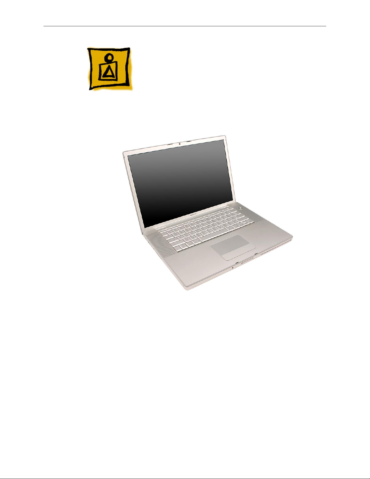
Product View
General Information
Overview
The MacBook Pro (15-inch 2.4/2.2GHz) is the third generation in Apple’s line of Intel-based
professional notebook computers. Based on a newer and more robust Intel Core 2 Duo chip, the
architecture supports faster clock speeds and increases bus speeds to 800 MHz. Speed aside,
the new system now addresses up to a full 4 GB of DDR2 memory and sports a new on-board
graphics chip: the NVIDIA GeForce 8600M GT.
The MacBook Pro (15-inch 2.4/2.2GHz) also introduces a new LED-driven, power-ecient display
backlight (the industry’s rst 15-inch) rather than using uorescent tube backlighting, eliminating
mercury from the display. Apple recently announced this technology publicly as part a new
corporate directive toward a “Greener Apple.”
From the exterior, the MacBook Pro (15-inch 2.4/2.2GHz) is identical in appearance to the previous
MacBook Pro (Core 2 Duo).
MacBook Pro (15-inch 2.4/2.2GHz) Basics— General Information 6
Page 7
Main service and feature differences from previous models:
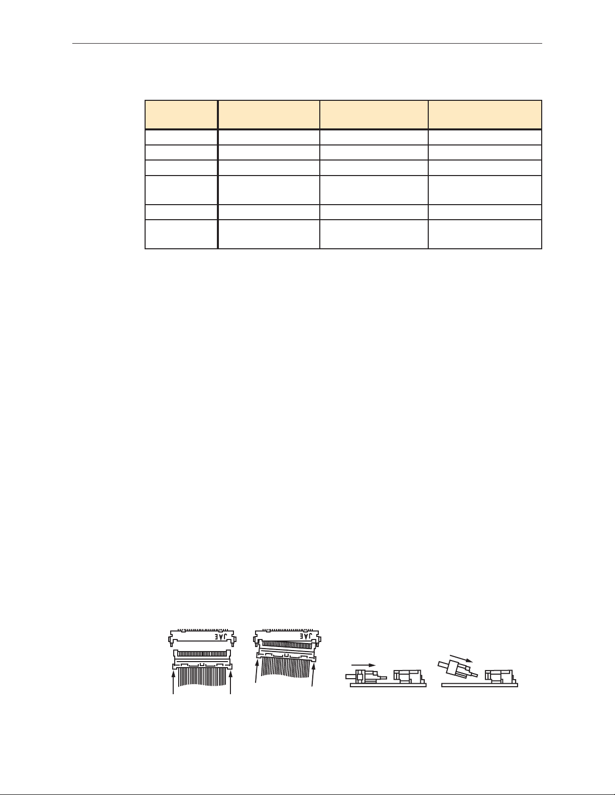
Correct Insertion Incorrect InsertionCorrect Insertion Incorrect Insertion
MacBook Pro (15-inch
2.4/2.2GHz)
Microprocessor 2.4/2.2GHz Core 2 Duo 2.33/2.16GHz Core 2 Duo 2.16/2.0/1.83GHz Core Duo
Bus Speed 800 MHz 667 MHz 667 MHz
Max RAM 4 GB 3 GB 2 GB
Graphics Chip NVIDIA GeForce
8600M GT
Display LED Backlight CCFL Backlight CCFL Backlight
Optical Drive 8x DVD Dual Layer
Superdrive
MacBook Pro (15-inch
Core 2 Duo)
ATI x1600 ATI x1600
6x DVD Dual Layer
Superdrive
MacBook Pro (15-inch)/
(15-inch Glossy)
4x DVD Superdrive
New Parts and Procedures
Main Logic Board
The main logic board of the MacBook Pro (15-inch 2.4/2.2GHz) now has a third thermal sensor
connector near the left fan. This thermal sensor is attached to the bottom case.
Memory
The maximum supported amount of memory is now 4 GB rather than 3 GB.
LED Backlight LCD Panel
The new LED backlit LCD panel can be easily identied in a couple ways. The display driver board
is now at the bottom of the panel instead of the top. The LVDS cable no longer travels up the
back of the display. In addition, the LED power is integrated into this cable.
This technology allows for a continuous backlight from the moment power is applied. Previously,
the uorescent tube required a warm-up period to reach operating brightness. Not only does
LED technology eliminate all mercury from the display, but also LEDs weigh less and provide
more brightness for the equivalent amount of power.
It is very important that the video ex connection to the LCD panel be properly inserted, aligned
and seated in its connector on the panel. Misalignment can cause multiple video issues. During
insertion, the connector should be perfectly straight, not at an angle, and the connector should
slide into its mate in a at position, parallel to the LCD panel, not obliquely. See illustration below.
MacBook Pro (15-inch 2.4/2.2GHz) Basics— General Information 7
Page 8

Keyboard
The side tabs on the upper right and left of the keyboard have been removed. The keyboard
drops right into the keyboard well rather than having to bend the corners to t in each side tab.
To compensate for the removal of the corner tabs, two screws have been added to the bottom.
ExpressCard Cage
The ExpressCard cage enclosure has been modied with multiple perforations in the metal to
cut down on weight and materials. In addition, “pocket screws” now secure the cage to the left
I/O board. These larger headed screws make contact with EMI gaskets on the bottom case for
improved noise isolation.
Temperature Concerns
The customer may perceive this system to run hotter than previous models. However, the normal
operating temperature is well within national and international safety standards. Still, customers
may be concerned about the heat generated by their machine. To prevent an unnecessary repair,
you can compare a customer’s computer to a running model, if available, at your repair site.
For more information on temperature concerns and customer perception, refer to Knowledge
Base article 30612: Apple Notebooks: Operating Temperature.
Display Takeapart
With the MacBook Pro (15-inch 2.4/2.2GHz), we are still utilizing the whole display clamshell as a
service part. However, some parts are accessible by the removal of the display rear housing.
Specically, a Service Provider can replace:
Display hooks•
Display housing•
Sleep magnet•
Camera board•
All other parts including the LVDS cable are serviced with the whole clamshell module.
MacBook Pro (15-inch 2.4/2.2GHz) Basics— General Information 8
Page 9
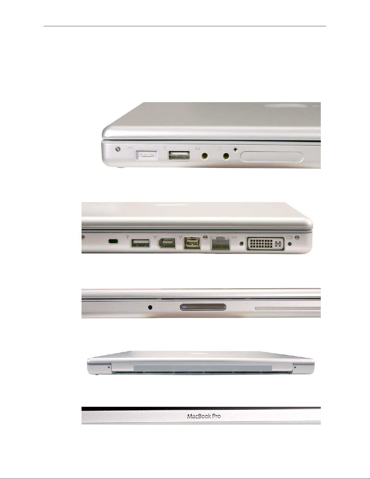
Identifying the MacBook Pro (15-inch 2.4/2.2GHz)
Below are external views of the MacBook Pro (15-inch 2.4/2.2GHz) which has no external features
that dierentiate it from its predecessor, the MacBook Pro (Core 2 Duo).
Left side: MagSafe™ power connector; USB, microphone, headphone ports; ExpressCard34 slot
Right side: Security lock slot; USB, FireWire 400, FireWire 800, Ethernet and DVI video ports
Front: Infrared sensor window
Rear: Same wider rear venting as the previous MacBook Pro (Core 2 Duo).
Display bezel: MacBook Pro
MacBook Pro (15-inch 2.4/2.2GHz) Basics— General Information 9
Page 10
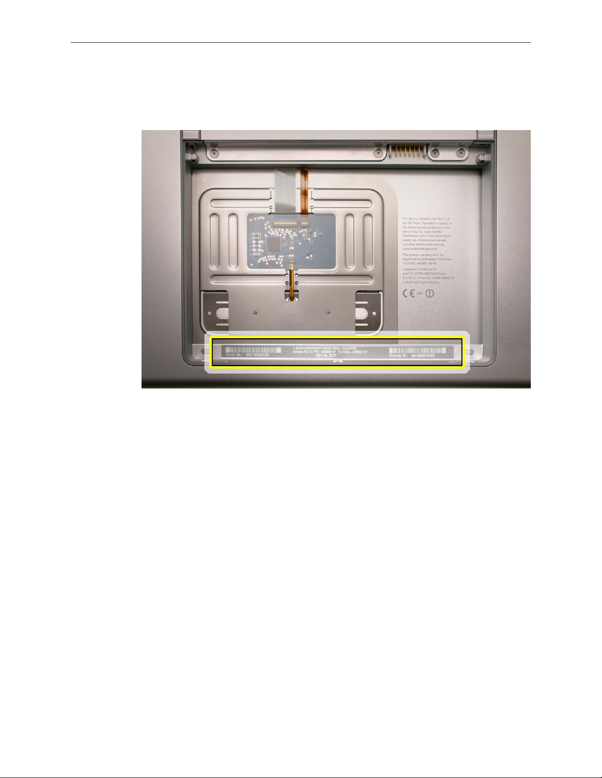
Serial Number and Ethernet ID
The Serial Number and Ethernet ID are located in the battery bay.
Tools
The takeapart procedure for the MacBook Pro (15-inch 2.4/2.2GHz) requires the following tools:
Clean non-marring work surface•
ESD wrist strap and mat•
Multi-compartment screw tray (such as a plastic ice cube tray)•
#0 Phillips screwdriver (magnetized)•
#1 Phillips screwdriver (magnetized)•
Torx T6 screwdriver (magnetized)•
4 mm socket wrench•
Black stick (nylon probe 922-5065) or other non-conductive nylon or plastic at-blade tool•
Razor knife•
Needle-point metal probe•
Needlenose pliers•
Tweezers•
Kapton tape (922-1731) (0.5-inch x 12-yard roll)•
Thermal grease (922-7144)•
Gasket kit (076-1261)•
Alcohol pads•
Fine-point felt-tip permanent marker•
Apple Pro keyboard and mouse (for troubleshooting)•
MacBook Pro (15-inch 2.4/2.2GHz) Basics— General Information 10
Page 11

Electrostatic Discharge (ESD)
Use a properly grounded ESD wrist strap and mat when working on the inside of the computer.
Service Manual Note
In this manual, graphics or photos are intended to help illustrate procedures or information only,
and may show dierent levels of disassembly, board colors, congurations, or computer models,
than your computer.
Kapton® Tape Note
Kapton tape is used to secure cables and connectors where necessary.
During disassembly, note any Kapton tape use and locations—reapply in the same manner. Do
not over apply or build up tape on top of old tape; space tolerances are tight and build up or
extraneous use of tape may cause pressure on other components.
Cable Routing Note
The MacBook Pro matches the same one-inch enclosure height established with the PowerBook
G4 17-inch series of systems. More so than ever, the placement of parts and wiring is critical.
During disassembly, note cable routing. Reassemble in the same manner. Verify that cables do
not route over components when they should route into lower positions or channels. Verify that
the cables are not strained or applying pressure onto other components.
Screw Measurement Note
All screw measurements given are the specied full length. Actual measured lengths may vary.
MacBook Pro (15-inch 2.4/2.2GHz) Basics— General Information 11
Page 12
Service Source
Adjustments
MacBook Pro (15-inch 2.4/2.2GHz)
© 2007 Apple Inc. All rights reserved.
Page 13

Latch Adjustment
Overview
If the display latches do not secure the display to the top case, or if they release before the
latch release button is pushed, an adjustment to the latch hooks can be made to correct this.
Alternately, the computer can be sent to the Apple Repair Center for service.
The display latches consists of a latch mechanism under the top case (it’s actually attached to
the bottom case frame) and two pivoting latch hooks within the display assembly. The hooks are
pulled down into the latch mechanism by a magnet as they approach the top case, and they are
secured under an overhang on the latch mechanism.
Tools
This procedure requires the following tools:
Black stick (or other non-marring nylon or plastic pointed tool)•
Magnet•
Preliminary Steps
Warning: While performing the following procedures, notice the hooks as they are drawn out
of the display housing and into the slots in the top case. If adjustments to either latch hook are
performed later, they must be adjusted only very slightly, to stay within the slot on the top case.
Before performing the latch adjustment, test the current operation of the latches:
Push the display down to about two inches from the top case. Then push the display very 1.
slowly until it just touches the top case, and immediately release.
If working properly, the latches should secure the display to the top case throughout the
following tests:
Pounding rmly on the table top, to the left and right of the computer.•
Pulling up on the sides of the display.•
Repeat the above procedures multiple times to verify proper operation of the latches.
Whether or not the latches functioned properly, use the following procedures to achieve or 2.
to verify proper latching function.
MacBook Pro (15-inch 2.4/2.2GHz) Adjustments — Display Latch 13
Page 14
Procedure
Note: The latch mechanism under the top case of the computer has a small amount of right and
left play (less than 1 mm), and can shift during normal operation.
The following procedures will test the latching function with the latch mechanism at its optimum
right and left positions, and the latch hooks will be very slightly adjusted, as necessary.
Important: The latch hook metal can become brittle and break if it is bent too much, especially
if it is over-bent and bent back. Work carefully and with due restraint to avoid over-bending the
latch hooks. If a latch hook breaks, new latch hooks will need to be ordered and replaced.
Open the display and note the edges of the latch mechanism underneath the top case, 1.
shown below, just to the right and left of the latch release button. This mechanism catches
both left and right latch hooks on the display assembly.
Use a black stick to push the latch mechanism, at the location shown below, by pushing from 2.
the right to move it to left as needed (less than 1 mm), or conversely, from the corresponding
location on the left side of the latch release button to move it right (less than 1 mm).
MacBook Pro (15-inch 2.4/2.2GHz) Adjustments — Display Latch 14
Page 15
Perform the testing procedures in step 1 of the Preliminary Steps, above.3.
If the latch functions properly, skip to step 6; otherwise, if either or both latch hooks require 4.
an adjustment, refer to the following steps below.
If the latch mechanism does not function properly, adjust the latch hook(s) as follows:5.
Open the display to a 90-degree angle and use a magnet to draw the latch hook out. Tightly
grasp it between your thumb and forenger as close to the display as possible, as shown.
Carefully exert a very slight controlled downward pressure on the latch hook.
Important: Do not push only with your thumb. Hold the latch hook tightly between your
thumb and forenger to support the latch hook and prevent too much bending force.
Release the latch hook, adjust the other latch hook as needed, and perform the latch tests as
before. Continue the above procedure until both latches function properly.
Again, if needed, use a black stick to push on the latch mechanism, as shown below, to move 6.
it to the left or right (about 1 mm) to re-center the mechanism over the latch release button.
Repeat the previous latch closing tests, and latch hook adjustment if needed, until the latch 7.
works properly in this position.
MacBook Pro (15-inch 2.4/2.2GHz) Adjustments — Display Latch 15
Page 16

Service Source
Take Apart
MacBook Pro (15-inch 2.4/2.2GHz)
© 2007 Apple Inc. All rights reserved.
Page 17
Foot
Tools
This procedure requires the following tools:
Foot kit•
Tweezers or needlenose pliers•
Soft cloth•
Preliminary Step
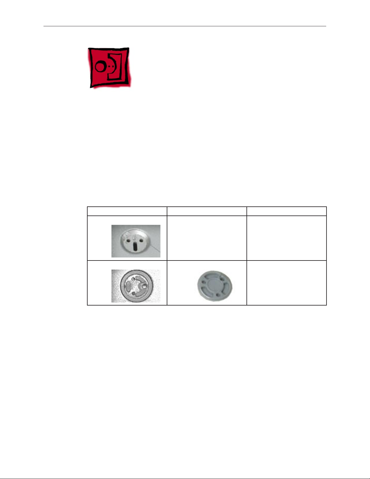
Before you begin, check the foot location that needs replacement and verify that the case plug is
attached. Also verify that the case plug, and the case foot in the kit, match the pictures below.
Plug Area on Bottom Case Matching Foot Action
Missing case plug Not available for replacement Replace the bottom case, or
send to Apple Repair Center.
Case plug Case foot Continue with the procedure,
matching the foot to the plug
on the bottom case.
MacBook Pro (15-inch 2.4/2.2GHz) Take Apart — Foot 17
Page 18
Procedure
Warning: The glue used in this procedure can bond instantly to skin. Do not touch the glue.
In the event of contact, review the safety instructions at the end of this document. For
additional information, refer to the glue manufacturer:
Elmer’s Products, Inc.
Columbus, OH. 43215-3799
www.krazyglue.com
Place the computer upside down on a clean, lint-free cloth or other nonabrasive surface.1.
Select a foot from the kit. Verify that the case plug and case foot match (refer to the images 2.
shown in the table). Do not use a foot that does not match.
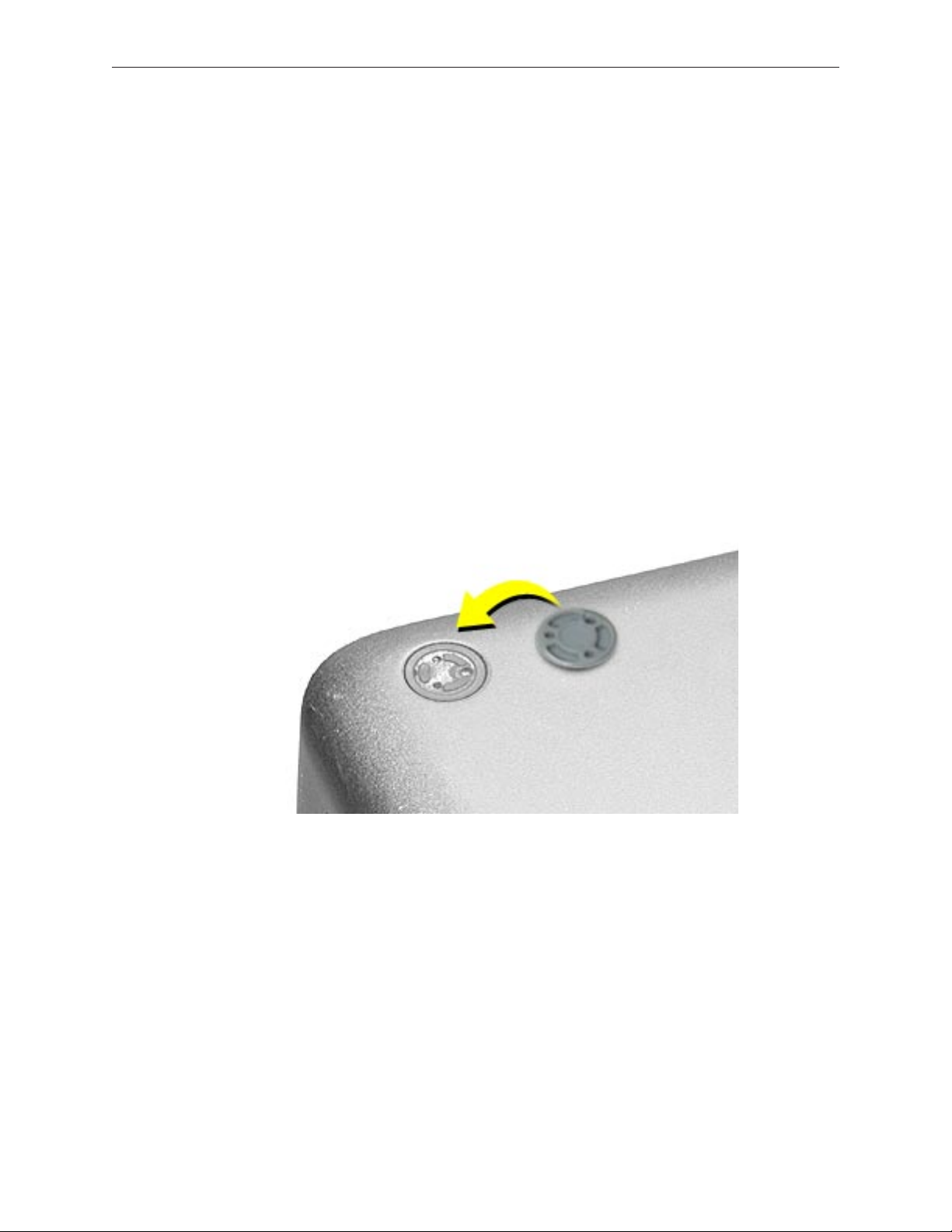
Make sure the plug area on the bottom case is clean. If any portion of the soft rubber foot 3.
remains, remove it so that only the hard plastic plug is visible.
Important: When positioning the foot, make sure the indents and bumps of the rubber foot
match up and t into the corresponding indents and bumps in the plug. This ensures a
balanced and level tting. (Note: The picture below may be a dierent foot than on the
computer, and is for illustration only.)
MacBook Pro (15-inch 2.4/2.2GHz) Take Apart — Foot 18
Page 19
4. Warning: GLUE IS AN EYE AND SKIN IRRITANT. BONDS SKIN INSTANTLY. Do not touch the
glue at any time. Before opening the glue, review the safety instructions at the end of
this document.
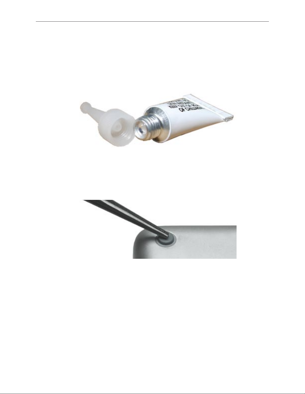
Important: The glue tube included in the kit is sealed until rst use. Do not break the seal
until you are ready to use the glue. To break the seal, hold the tube upright and away from
you. Place the hollow nozzle cap on the tube and tighten it all the way down. The tube is
then ready to dispense the glue through the nozzle cap.
Apply one drop of glue to the plug on the bottom case. Do not spread the glue.5.
Using tweezers or needlenose pliers, carefully position the new foot so its textured surface 6.
ts into the inner ring of the plug.
Using the end of the tweezers or pliers—not your nger—lightly press and hold the foot in 7.
place for 30 seconds.
Before turning over the computer, allow the glue to set for at least 15 minutes.8.
Discard the tube of glue.9.
SAFETY INSTRUCTIONS: GLUE IS AN EYE AND SKIN IRRITANT. BONDS SKIN
INSTANTLY. Contains ethyl cyanoacrylate. Avoid contact with skin and eyes. If eye or mouth
contact occurs, hold eyelid or mouth open and rinse thoroughly but gently with water only for 15
minutes and GET MEDICAL ATTENTION. Liquid glue will sting eye temporarily. Solidied glue
may irritate eye like a grain of sand and should be treated by an eye doctor. If skin bonding occurs,
soak in acetone-based nail polish remover or warm soapy water and carefully peel or roll skin
apart (do not pull). Contact through clothing may cause skin burn. If spilled on clothing, ush with
cold water. Avoid prolonged breathing of vapors. Use with adequate ventilation. KEEP OUT OF
REACH OF CHILDREN.
MacBook Pro (15-inch 2.4/2.2GHz) Take Apart — Foot 19
Page 20
Battery
Tools
This procedure requires the following tools:
Clean non-marring work surface•
Preliminary Steps
Warning: Always shut down the computer before opening it to avoid damaging its internal
components or causing injury. After you shut down the computer, the internal components
can be very hot. Let the computer cool down before continuing.
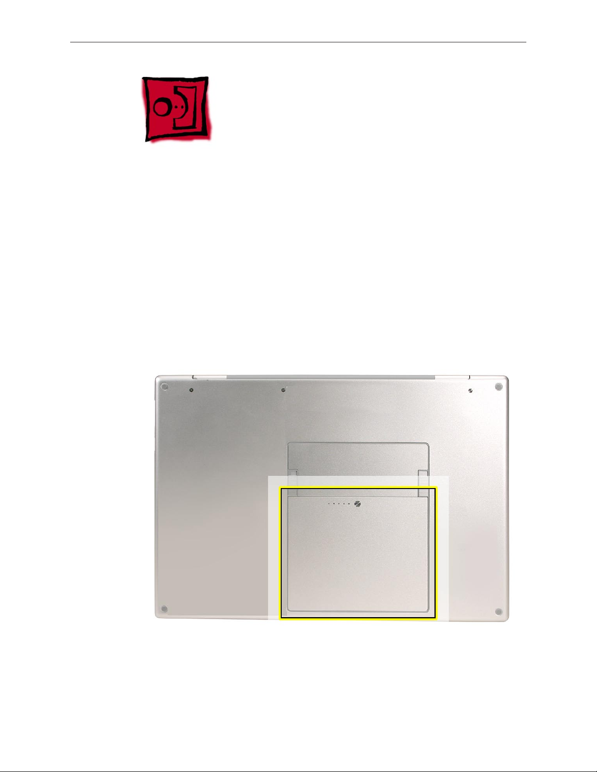
Part Location
MacBook Pro (15-inch 2.4/2.2GHz) Take Apart — Battery 20
Page 21
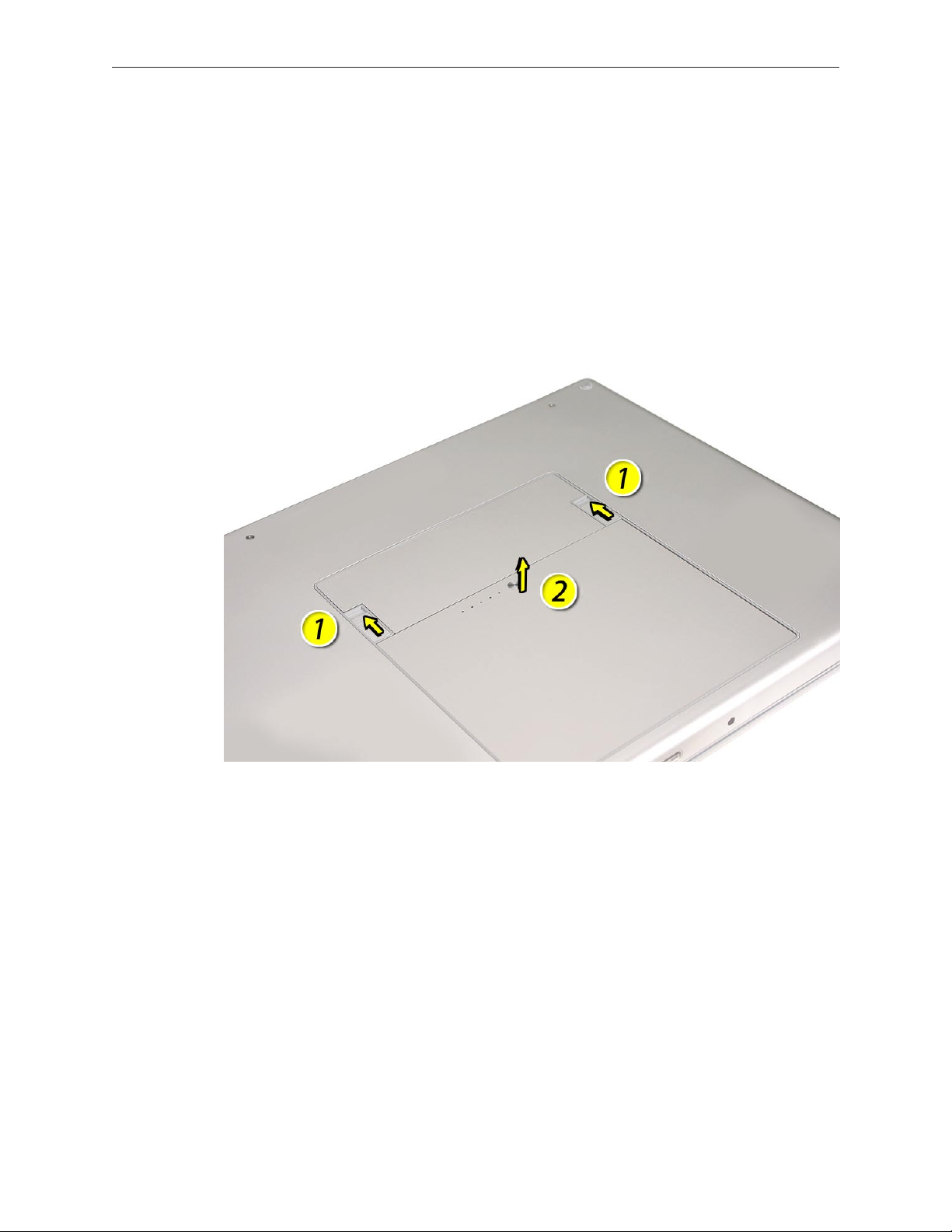
Procedure
Warning: If the computer has been recently operating, allow it to cool down before
performing this procedure.
Shut down the computer.1.
Disconnect the power cord and any other cables connected to the computer.2.
Place the computer face down.3.
Slide both battery latches away and lift the battery out of the battery bay.4.
MacBook Pro (15-inch 2.4/2.2GHz) Take Apart — Battery 21
Page 22
Memory
Tools
This procedure requires the following tools:
#0 Phillips screwdriver (magnetized)•
Clean non-marring work surface•
ESD wrist strap and mat•
Preliminary Steps
Before you begin, remove the following:
Batter• y
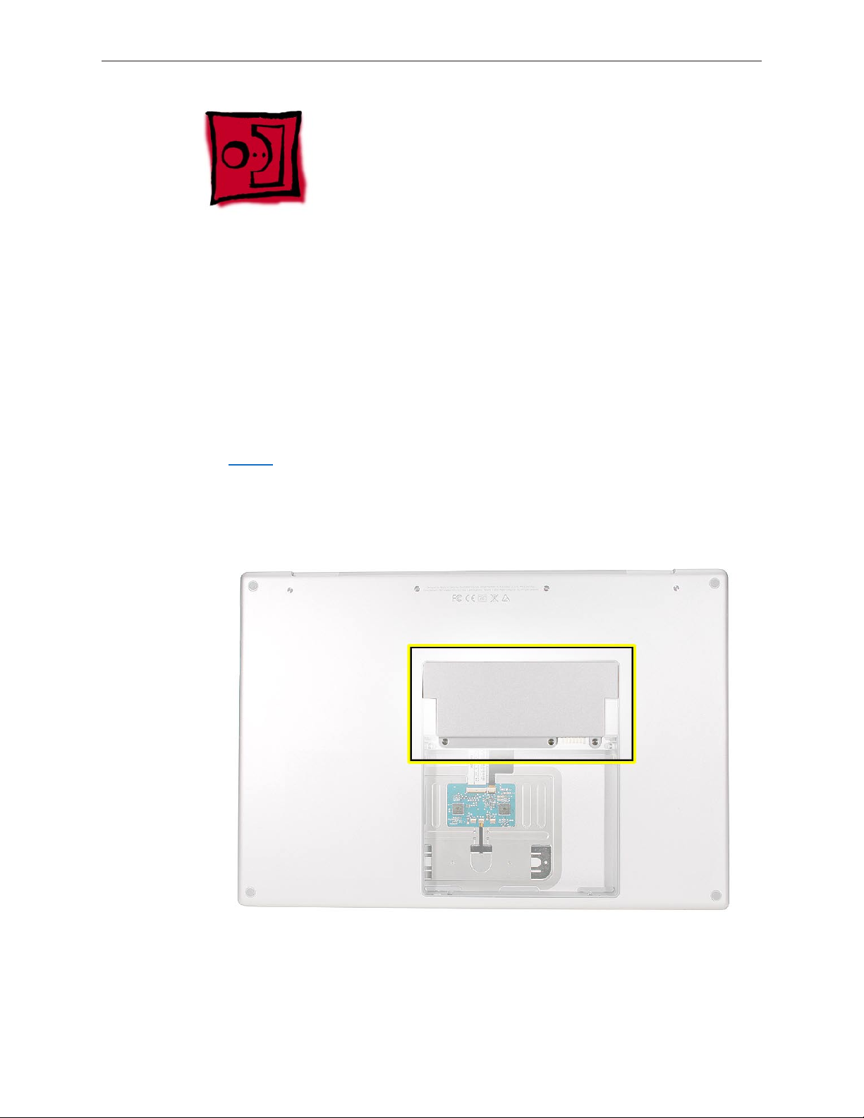
Part Location
MacBook Pro (15-inch 2.4/2.2GHz) Take Apart — Memory 22
Page 23
Procedure
Warning: If the computer has been recently operating, allow it to cool down before
performing this procedure.
Place the computer face down.1.
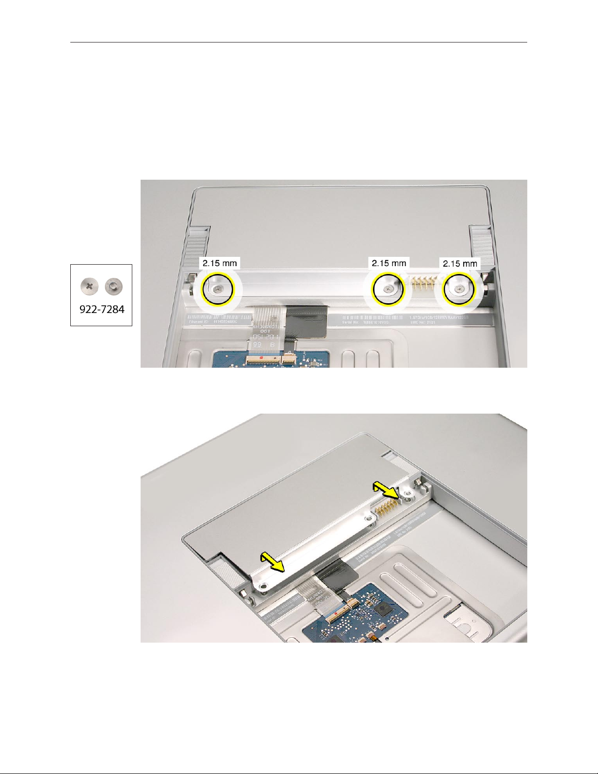
Remove the three Phillips screws from the memory door. 2.
Remove the door, as shown. 3.
Notes:
• If only one memory card is installed, the factory installs it in the bottom memory slot.
• Memory must be removed from the top slot before removing from the bottom slot.
MacBook Pro (15-inch 2.4/2.2GHz) Take Apart — Memory 23
Page 24
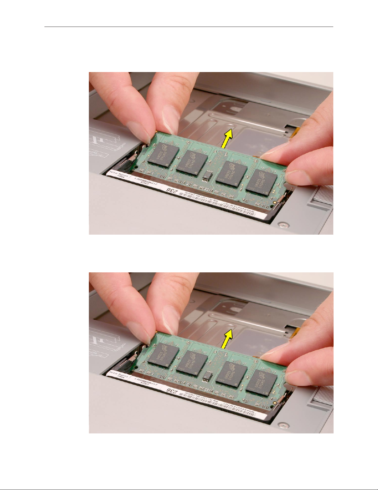
To remove memory cards, carefully spread the two locking tabs for the slot (top or bottom) 4.
away from the card on both sides and allow the card to pop up slightly.
Pull the card straight back and out of the memory slot. Handle the memory card by the 5.
edges only, taking care not to touch the gold contacts.
MacBook Pro (15-inch 2.4/2.2GHz) Take Apart — Memory 24
Page 25
Replacement Procedure
Notes:
DDR memory cards do not t in this slot, only DDR2 (dierent notch location).•
If installing two cards, install the rst card into the bottom slot before the top slot. •
Align the notch in the memory card with the tooth in the slot before inserting.•
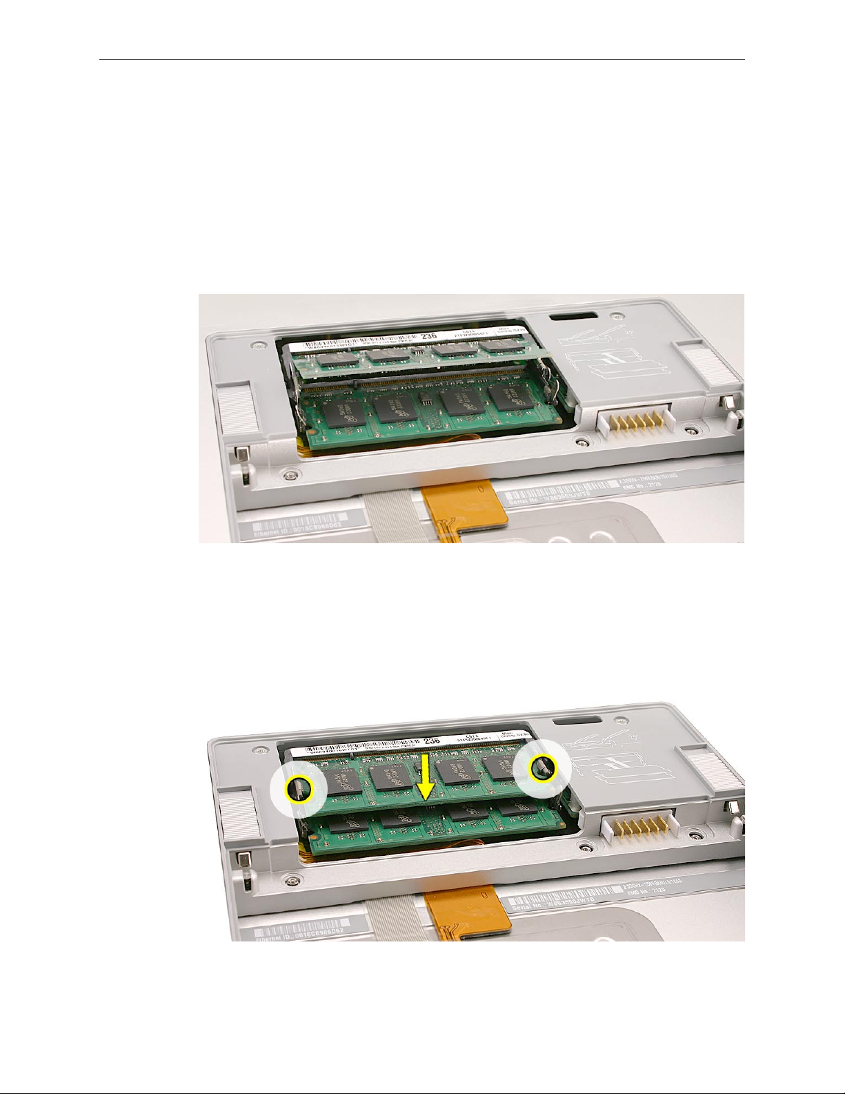
To install memory cards, insert them at a 30-degree angle. ‘1.
Note: Insert the bottom card behind the locking tabs of the top slot.
Firmly push the card straight into the slot until it is fully and securely seated along its length. 2.
Note: If the back of the card drops down before it is fully seated, raise it up enough to push
it fully into the slot.
When the card is fully seated, push the card straight down until the tabs click onto both 3.
sides of the card, locking it into place.
MacBook Pro (15-inch 2.4/2.2GHz) Take Apart — Memory 25
Page 26
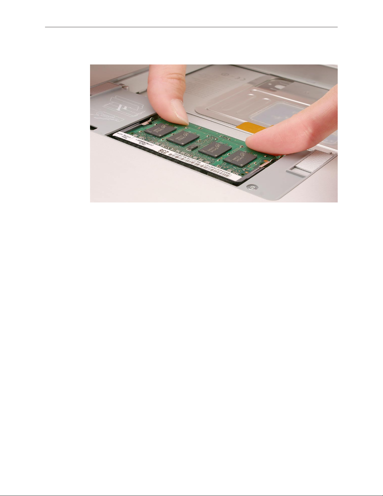
Verify that the card is fully seated by pushing rmly with your thumbs. 4.
Check that the cards are secured by the brackets on both sides.5.
Install the memory door.6.
Replace the battery.7.
Use Apple System Proler to verify that the memory is recognized. (Choose the menu 8.
bar Apple logo () > About This Mac, click More Info..., select the System Prole tab,
open the Memory Overview.)
MacBook Pro (15-inch 2.4/2.2GHz) Take Apart — Memory 26
Page 27
Top Case
Tools
This procedure requires the following tools:
#0 Phillips screwdriver (magnetized)•
Torx T6 screwdriver (magnetized)•
Black stick (nylon probe 922-5065) or other non-conductive nylon or plastic at-blade tool•
Multi-compartment screw tray (such as a plastic ice cube tray)•
Preliminary Steps
Before you begin, remove the following:
Batter• y
Memory Doo• r
Part Location
MacBook Pro (15-inch 2.4/2.2GHz) Take Apart — Top Case 27
Page 28
Procedure
Notes:
If replacing the top case, once the top case is removed, use a razor knife to carefully lift and •
transfer the Serial Number and Ethernet ID labels to the replacement top case.
This procedure removes the top case and keyboard assembly. The keyboard is removable •
only after removing the top case.
Place the computer upside down on a soft, non-marring surface.1.
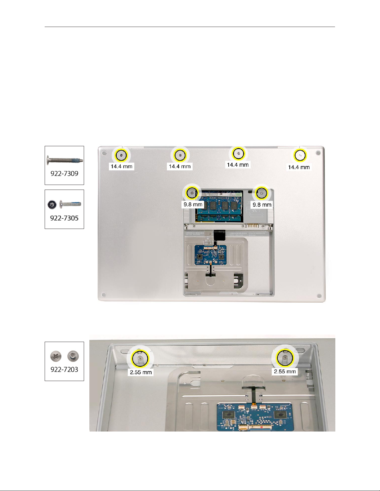
2. Remove the four Phillips and two Torx T6 screws shown.
3. Rotate the computer and remove the two Phillips screws along the front of the battery bay.
MacBook Pro (15-inch 2.4/2.2GHz) Take Apart — Top Case 28
Page 29
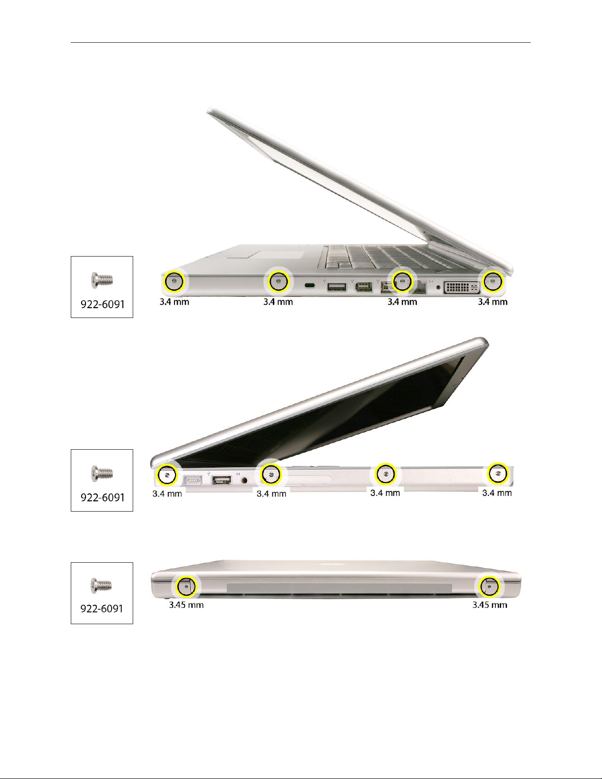
4. Remove the four Phillips screws from each side.
5. Remove the two Phillips screws from the back edge.
.
MacBook Pro (15-inch 2.4/2.2GHz) Take Apart — Top Case 29
Page 30
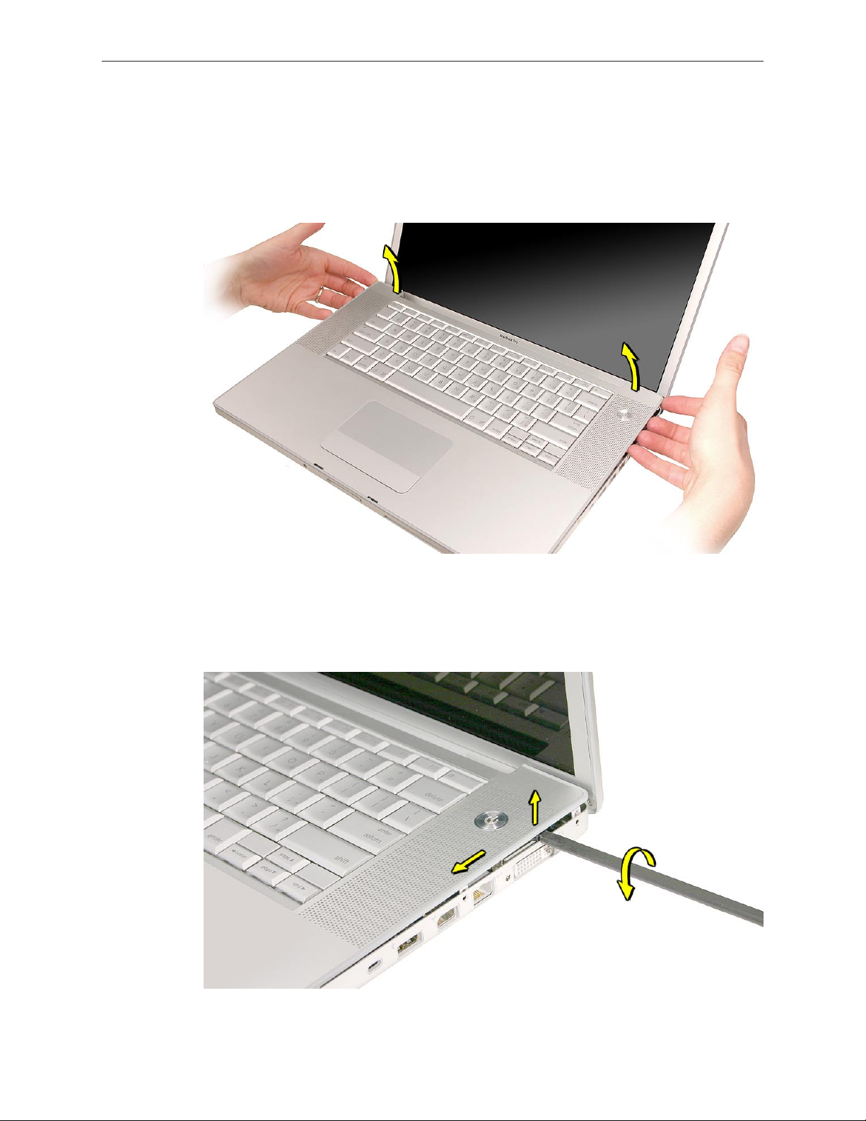
Face the computer toward you with the display open slightly past 90-degrees. Using your 6.
ngernails or the tips of your ngers, grasp just beneath the top case in the upper right and
left corners. Lift upward a few inches, then work your hands around the top case toward the
front, slowly lifting and encouraging the clips and screw tabs to release. A snapping noise
when the clips release is normal.
Note: Take care to preserve the cosmetic integrity of the plastic beading around the edges of the
top case. If using a black stick for leverage to get the clips to release, don’t rotate the stick too
much along the edges to avoid denting the soft plastic.
MacBook Pro (15-inch 2.4/2.2GHz) Take Apart — Top Case 30
Page 31

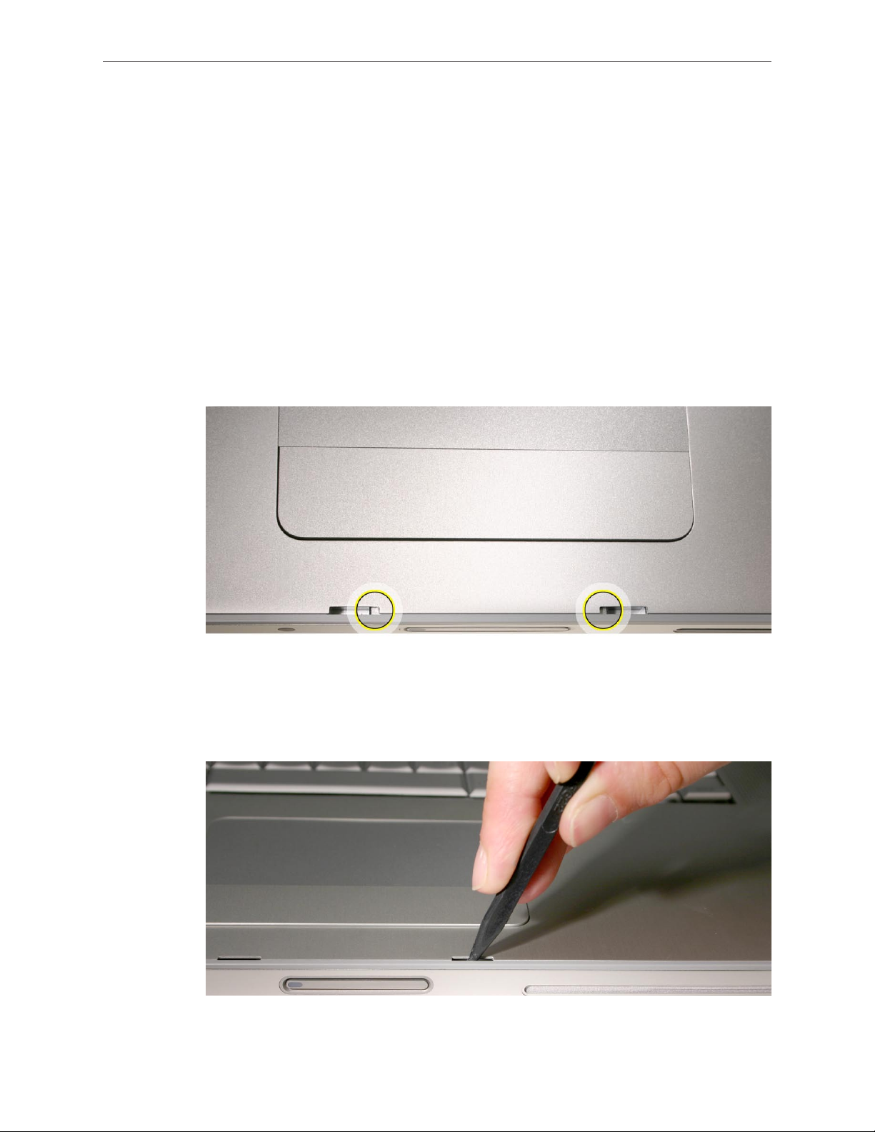
Along the front, start at the left and slowly encourage the snaps and screw tabs (shown in 7.
graphic below) to release as you move right. A snapping noise as the snaps release is normal.
Again, take care to preserve the cosmetic integrity of the plastic beading around the edges
by pulling up with your ngernails rst. If a black stick is necessary to release the snaps, avoid
too much rotation along the edges to keep from denting the soft plastic.
Important: Do not lift the case once it is free—it is still connected to the bottom case by the
keyboard ex cable.
MacBook Pro (15-inch 2.4/2.2GHz) Take Apart — Top Case 31
Page 32

Important: To avoid bending screw tabs along the back edge of the top case, lift the top case
slightly so that it does NOT touch the bottom case, then rotate the front of the case up and back
until you can disconnect the keyboard ex cable from the logic board.
MacBook Pro (15-inch 2.4/2.2GHz) Take Apart — Top Case 32
Page 33

Replacement Procedure
Note: If replacing the top case, remove the keyboard and transfer to the replacement top case.
(See keyboard section in next chapter for replacement instructions.)
Visually check to verify that all cables are connected and routed correctly with nothing raised 1.
up or incorrectly placed over a component.
Check perimeter wiring and cables around clutches to verify that they will not be caught or 2.
pinched by the top case during replacement.
On the computer, verify that all cables are secure and lay at.3.
On the top case, check cable connections and routing.4.
Note: Unique identiers for this top case: the right ALS dust cover mounted with adhesive and a
small bit of copper tape under an opening in the black mylar lm over the keyboard.
MacBook Pro (15-inch 2.4/2.2GHz) Take Apart — Top Case 33
Page 34

Check that the perimeter screw tabs and ribs are not bent. 5.
Note: The metal can quickly fatigue and break o. Be extremely careful to gently straighten
tabs, if needed.
Verify that the plastic spacer is on the front screw tab, shown. 6.
MacBook Pro (15-inch 2.4/2.2GHz) Take Apart — Top Case 34
Page 35

Verify that the screw tabs in back are straight and guide them inside the bottom case. Work 7.
your way around guiding the screw tabs into the bottom case along both sides.
If the back screw tabs are bent out, straighten by pressing the edge of the case on a hard at 8.
surface and rolling to vertical.
MacBook Pro (15-inch 2.4/2.2GHz) Take Apart — Top Case 35
Page 36

Any screw tabs that are not straight will not t or accept screws correctly. 9.
Use your nger and a black stick to carefully straighten bent screw tabs. 10.
MacBook Pro (15-inch 2.4/2.2GHz) Take Apart — Top Case 36
Page 37

Connect the ex cable from the top case to the logic board.11.
Lift the top case o the bottom case slightly and rotate it down (verify that the keyboard 12.
cable stays connected and is folding properly) and align the corners.
Carefully pull or push tabs slightly, if needed. 13 .
Note: Guarded, controlled pushing with your thumb may be helpful to gently nesse the
tabs into place.
The two front screw tabs may need to be guided with a black stick through the battery bay.14.
Squeeze at the snap locations (shown below) along the front edge of the top case to verify 15 .
that the they are seated. You should hear ve audible snaps when pressing down the front
edge of the top case. The top case should lay at along all sides and top, if not, make sure
that cables and components are not interfering.
To minimize any cosmetic gaps between the edges of the top and bottom case, rmly press 16.
down the top case with your ngers, squeezing the cases together at each location while
installing the left and right side screws, especially toward the front of the computer.
Important: Do not insert screws into the DVI port screw holes. If they get stuck, it may
require removing the logic board to dislodge.
MacBook Pro (15-inch 2.4/2.2GHz) Take Apart — Top Case 37
Page 38

Install the bottom Phillips screws and the two Torx T6 screws near the memory chips. 17.
Using the at end of a black stick to gently wedge the edge of the top case toward the 18.
bottom case to minimize gaps, install the two Phillips screws along the back.
.
MacBook Pro (15-inch 2.4/2.2GHz) Take Apart — Top Case 38
Page 39

Install the two Phillips screws in the battery bay. 19.
Important: For the screw shown, push in the display latch button while installing the screw.
Check that the edges of the top case sit ush with the bottom case around the entire 20.
perimeter of the computer. If there are noticeable gaps, reinstall the top case taking extra
care to secure top case top bottom when replacing the perimeter screws.
Install the memory door and replace the battery. 21.
Testing the computer should include:22.
Powering on, checking the keyboard and trackpad function. •
Operate the computer in a darkened room to check for keyboard backlight function.•
Verify Bluetooth operation by checking that the it appears in either the Apple Menu bar •
or in the Apple System Proler USB section.
MacBook Pro (15-inch 2.4/2.2GHz) Take Apart — Top Case 39
Page 40

Keyboard
Tools
This procedure requires the following tools:
#0 Phillips screwdriver (magnetized)•
Black stick (nylon probe 922-5065) or other non-conductive nylon or plastic at-blade tool•
Preliminary Steps
Before you begin, remove the following:
Batter• y
Top Cas• e
Part Location
MacBook Pro (15-inch 2.4/2.2GHz) Take Apart — Keyboard 40
Page 41

Procedure
Important Notes:
The MacBook Pro (15-inch 2.4/2.2GHz) keyboard is not interchangeable with any previous •
models, including the original MacBook Pro and the MacBook Pro (Core 2 Duo). If replacing
the keyboard, verify that the correct replacement keyboard and/or top case is ordered.
The keyboard comes as a multi-layered assembly and includes backlighting. Do not •
disassemble the keyboard itself. Dust, ngerprints, or misalignment can cause improper
function and damage to the assembly.
On a clean at surface, turn the top case upside down.1.
Locate the protective cover over the ex cable connectors as shown below. 2.
MacBook Pro (15-inch 2.4/2.2GHz) Take Apart — Keyboard 41
Page 42

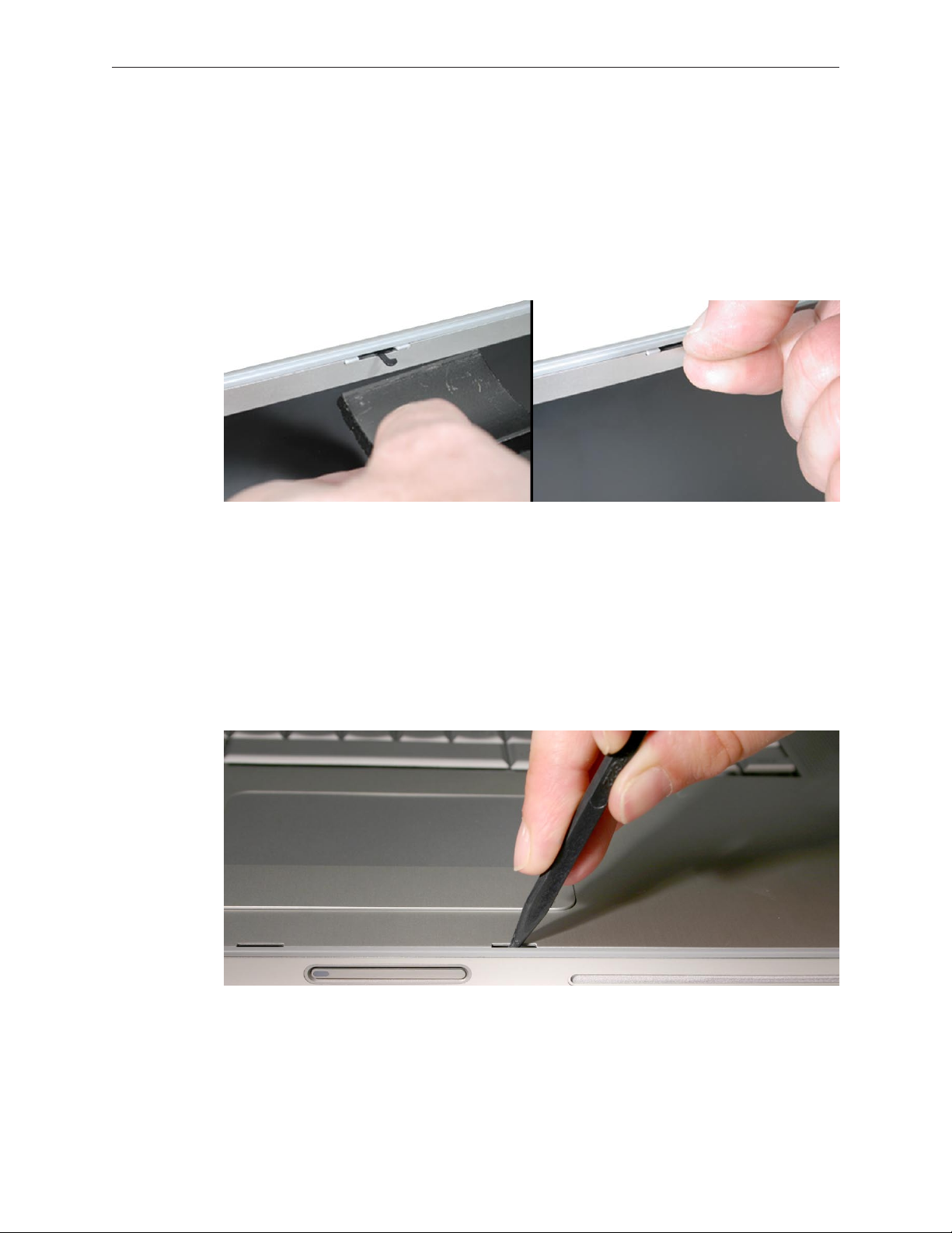
Rotate the top case to have the cable connectors facing you for better access. Carefully lift 3.
the perimeter of the cover nearest the cable connectors to release the adhesive. If necessary,
use a razor knife to lift up the edge enough to slide in a black stick (see inset below).
Gently lift and hold up that half of the cover with the black stick to provide adequate access 4.
to the connectors. Important: Keep the cover and its underlying adhesive clean and intact.
Remove any Kapton tape, then very carefully lift the latches of the connectors to release the 5.
cables. Important: The connectors are delicate. If damaged, the top case must be replaced.
MacBook Pro (15-inch 2.4/2.2GHz) Take Apart — Keyboard 42
Page 43

Note the positioning, then carefully peel o the insulator lm covering the back of the 6.
keyboard well. Reserve the lm and keep it clean for reinstallation.
Important: Use care at the notches and narrow parts to avoid ripping or tearing the lm.
Important: If any rubber pads are present, do not remove them if not replacing the top case. If
replacing the top case, transfer them to the same location.
MacBook Pro (15-inch 2.4/2.2GHz) Take Apart — Keyboard 43
Page 44

Use needlenose pliers to gently straighten the six bend-tabs located along the bottom edge, 7.
as shown. These tabs lock down and stien the top edge of the keyboard. Important: The
bend-tabs are delicate. Bend them carefully to avoid damage. Avoid over-bending.
Remove the twelve Phillips #00 keyboard screws. Be sure to sandwich keyboard to top case 8.
when removing the nal screws.
MacBook Pro (15-inch 2.4/2.2GHz) Take Apart — Keyboard 44
Page 45

To prevent the keyboard from falling out, support it with your hand, and raise the top case 9.
up vertically. Note: This keyboard has no side tabs like previous models.
If you lean the top case toward you top rst, the keyboard may simply fall into your hands. 10.
MacBook Pro (15-inch 2.4/2.2GHz) Take Apart — Keyboard 45
Page 46

Note the six insert-tabs along the bottom edge of the keyboard that tuck into the lower 11.
edge of the keyboard well.
Lift the keyboard up and away from the top case to release the tabs along the bottom edge 12.
and carefully thread out the ex cables. Important: During this procedure, do not allow the
tabs or metal edge of the keyboard to scrape along the cosmetic surface of the top case;
otherwise damage can result.
MacBook Pro (15-inch 2.4/2.2GHz) Take Apart — Keyboard 46
Page 47

Replacement Procedure
When replacing the keyboard, here are some key points to keep in mind:
Prevention of scratches to the cosmetics of the top case•
All tabs are properly seated•
Keyboard lays at•
Bend-tabs are not damaged•
Screw holes align•
Cables are not caught•
Cable connectors are not damaged and cables are secure•
Kapton tape is applied as before•
Insulator lm is correctly installed•
Before installing a replacement keyboard, verify that the six bend-tabs along the bottom 1.
edge of the keyboard are straight and parallel with the edge (shown close-up below).
Important: Do not bend any other bend-tabs on the keyboard other than the six along the
bottom. Other tabs hold the layered keyboard assembly together.
Guide the keyboard’s ex cables through the slot in the top case, as shown. Make sure that 2.
they do not catch, bend or get pinched behind the keyboard.
MacBook Pro (15-inch 2.4/2.2GHz) Take Apart — Keyboard 47
Page 48

Verify that the small backlight cable routes through the slot, as shown. 3.
Lower the keyboard into the well and seat all six tabs along the bottom, so that the keyboard 4.
sits at and straight.
MacBook Pro (15-inch 2.4/2.2GHz) Take Apart — Keyboard 48
Page 49

Verify that the bend-tabs are not caught.5.
Pull on the ex cables to verify that they are not bent or caught under the keyboard, and 6.
that they extend to their connectors.
Verify that the screw holes align with the screw bosses, and, holding the keyboard in place 7.
with your other hand, work outward from the middle to install all twelve keyboard screws.
Bend the six bend-tabs over the metal of the top case to secure the edge of the keyboard. 8.
Important: The bend-tabs are delicate. Bend them carefully to avoid damage and no more
than 90 degrees, or to, or within, any etch marks, if present. Avoid over-bending.
MacBook Pro (15-inch 2.4/2.2GHz) Take Apart — Keyboard 49
Page 50

Insert the two ex cables into their connectors and secure. Verify that the cables are fully 9.
inserted and secured straight. Kapton tape will be applied to the small connector later.
Reinstall the protective cover over the area shown. Carefully burnish down the edges to 10.
secure. (top case shown rotated)
MacBook Pro (15-inch 2.4/2.2GHz) Take Apart — Keyboard 50
Page 51

Replace the insulator lm in the same location from which it was removed. Ensure the holes 11 .
in the lm match up correctly with the screw bosses. Avoid wrinkles and bulges. If installing
a replacement top case, use the new lm if supplied.
Important: The lm must be installed in the same location to protect against contact and
electrical shorting in certain areas as well as to allow connection with the EMI spring on the
logic board.
Install Kapton tape to secure the small ex cable connector.12.
Verify that any rubber pads (mentioned earlier) are installed in the correct locations.13 .
If the lm extends over the edge of the keyboard well, run your nger along the edges to 14.
secure it to the top case.
Reassemble the computer.15 .
Testing the computer should include powering on the unit, checking keyboard and trackpad 16.
function. Operate the computer in a darkened room to check for keyboard backlight
function, as well as light leakage around the perimeter of the keyboard, speaker grill
openings and side ports.
MacBook Pro (15-inch 2.4/2.2GHz) Take Apart — Keyboard 51
Page 52

AirPort Extreme Card
Tools
This procedure requires the following tools:
Torx T6 screwdriver (magnetized)•
Black stick (nylon probe 922-5065) or other non-conductive nylon or plastic at-blade tool•
Kapton tape (922-1731) (0.5-inch x 12-yard roll)•
Preliminary Steps
Before you begin, remove the following:
Batter• y
Top Cas• e
Part Location
MacBook Pro (15-inch 2.4/2.2GHz) Take Apart — AirPort Extreme Card 52
Page 53

Procedure
Remove the three antenna connectors. Lift straight up.1.
Remove the Torx T6 screw and bracket, and peel up any kapton tape holding down the 2.
Airport card, if present. The card should rise up slightly.
3. Pull the card straight out.
MacBook Pro (15-inch 2.4/2.2GHz) Take Apart — AirPort Extreme Card 53
Page 54

Verify that the antenna cables route at in the channel and underneath the two brackets on 4.
the left speaker. Secure with Kapton tape, if necessary.
5. Connect each antenna cable to its respective terminal. Note that the color of each antenna
cable corresponds with a matching color key located above the terminals.
6. Verify that the ambient light sensor ex cable is connected properly.
Reassemble the computer.7.
Testing should include AirPort function. 8.
Quick Test: Open up Apple System Proler to make sure the Airport Extreme card is
recognized under the AirPort Card tab in the Network section.
MacBook Pro (15-inch 2.4/2.2GHz) Take Apart — AirPort Extreme Card 54
Page 55

Bluetooth Card
Tools
This procedure requires the following tools:
#0 Phillips screwdriver (magnetized)•
Black stick (nylon probe 922-5065) or other non-conductive nylon or plastic at-blade tool•
Kapton tape (922-1731) (0.5-inch x 12-yard roll)•
Preliminary Steps
Before you begin, remove the following:
Batter• y
Top Cas• e
Part Location
MacBook Pro (15-inch 2.4/2.2GHz) Take Apart — Bluetooth Card 55
Page 56

Procedure
Disconnect the Bluetooth antenna connector from the Bluetooth card, pulling straight up.1.
Remove one Phillips screw from the lower right corner of the Bluetooth card.2.
Remove the plastic protective cover by sliding it gently o the card, taking care to preserve 3.
its integrity for reuse. Set the cover aside to use with the replacement Bluetooth card.
Holding the Bluetooth card by its edges, use a black stick to disconnect the cable connector 4.
from the card as shown below.
Replacement Note: Before attaching the new Bluetooth card to the top case, install the plastic
cover retained from the old card over the replacement and secure with Kapton tape if necessary.
MacBook Pro (15-inch 2.4/2.2GHz) Take Apart — Bluetooth Card 56
Page 57

Replacing the Bluetooth cable
To remove or replace the Bluetooth cable, gently pry up adhesive using a black stick.1.
Disconnect the other end of the cable as shown.2.
Quick Check: Use Apple System Proler to see if Bluetooth HCI appears under the USB Bus tab
in the USB device section.
MacBook Pro (15-inch 2.4/2.2GHz) Take Apart — Bluetooth Card 57
Page 58

Bluetooth Antenna
Tools
This procedure requires the following tools:
#0 Phillips screwdriver (magnetized)•
Black stick (nylon probe 922-5065) or other non-conductive nylon or plastic at-blade tool•
Razor knife•
Kapton tape (922-1731) (0.5-inch x 12-yard roll)•
Preliminary Steps
Before you begin, remove the following:
Batter• y
Top Cas• e
Part Location
MacBook Pro (15-inch 2.4/2.2GHz) Take Apart — Bluetooth Antenna 58
Page 59

Procedure
Disconnect the Bluetooth antenna connector from the Bluetooth card, pulling straight up. 1.
Remove two captured Phillips #0 screws from black plastic antenna shield which are 2.
accessible via screwdriver through two visible holes in the foam cover.
MacBook Pro (15-inch 2.4/2.2GHz) Take Apart — Bluetooth Antenna 59
Page 60

Pry shield up from top case using a black stick, taking care to preserve adhesive underneath. 3.
Use a black stick to remove the antenna, prying it up to release the adhesive. 4.
Replacement Note: If you remove the Bluetooth board during antenna replacement, reapply its
protective cover and secure with Kapton tape if necessary before reinstalling on the top case.
MacBook Pro (15-inch 2.4/2.2GHz) Take Apart — Bluetooth Antenna 60
Page 61

Infrared Board
Tools
This procedure requires the following tools:
Torx T6 screwdriver (magnetized)•
Black stick (nylon probe 922-5065) or other non-conductive nylon or plastic at-blade tool•
Preliminary Steps
Before you begin, remove the following:
Batter• y
Top Cas• e
Part Location
MacBook Pro (15-inch 2.4/2.2GHz) Take Apart — Infrared Board 61
Page 62

Procedure
Disconnect the cable.1.
Remove the Torx T6 screw and bracket.2.
Using a black stick, lift out the infrared board. Lifting from both ends may be helpful. 1.
Important: Lift on the board only. Do NOT lift the infrared lens or sensor piece. It is secured
to the main board with two wires and will bend out of alignment.
MacBook Pro (15-inch 2.4/2.2GHz) Take Apart — Infrared Board 62
Page 63

Note the cable routing and remove. Be sure to slip the cable out from under the small peg in 2.
the frame.
Replacement Procedure
Route the cable as above.1.
To install, insert the board all the way into the channel, then push it forward until it stops 2.
and the infrared lens aligns with the window.
Important: Push on the board only. Do NOT push on the infrared lens or sensor piece. It is
secured to the main board with two wires and will bend out of alignment.
Connect the cable connector.3.
Quick Test: Open Apple System Proler and check to see that IR Receiver appears under the USB
Bus tab in the USB device section.
MacBook Pro (15-inch 2.4/2.2GHz) Take Apart — Infrared Board 63
Page 64

Hard Drive
Tools
This procedure requires the following tools:
#0 Phillips screwdriver (magnetized)•
Torx T6 screwdriver (magnetized)•
Black stick (nylon probe 922-5065) or other non-conductive nylon or plastic at-blade tool•
Kapton tape (922-1731) (0.5-inch x 12-yard roll)•
Preliminary Steps
Before you begin, remove the following:
Batter• y
Top Cas• e
Part Location
MacBook Pro (15-inch 2.4/2.2GHz) Take Apart — Hard Drive 64
Page 65

Procedure
NOTE: Some hard drives may have a metal disk attached to them for vibration stabilization
(as shown below) while other models may not.
Carefully pry up the ex cable from the hard drive. 1.
Lift up cabling to gain some clearance. 2.
MacBook Pro (15-inch 2.4/2.2GHz) Take Apart — Hard Drive 65
Page 66

Remove the two Phillips #0 screws from the drive bracket.3.
Remove the hard drive bracket.4.
MacBook Pro (15-inch 2.4/2.2GHz) Take Apart — Hard Drive 66
Page 67

Using a black stick, tilt the hard drive up slightly on the right side; then work the hard drive 5.
out of its grommet wells on the left side and lift up just enough to access the ex connector.
If there is Kapton tape securing the ex connector, remove it very carefully to ensure that 6.
you don’t damage the label. A damaged label voids the warranty of the hard drive.
MacBook Pro (15-inch 2.4/2.2GHz) Take Apart — Hard Drive 67
Page 68

Kapton tape may wrap all the way around the ex connector to the back side of the hard 7.
drive. If so, hold the hard drive by its sides to turn it over and release the Kapton tape.
Gently pry the ex connector from the hard drive.8.
MacBook Pro (15-inch 2.4/2.2GHz) Take Apart — Hard Drive 68
Page 69

Replacement Procedure
Transfer the rubber grommets and screws. Replace any Kapton tape around ex cable.1.
NOTE: Some hard drives may have a metal disk attached to them for vibration stabilization.
Do not transfer this disk if the replacement drive comes without one. If a replacement hard
drive needs this metal disk, it will come preattached.
Tilting the hard drive as you insert it, tuck the screws on the left side of the hard drive into 2.
the grommets in the bottom case.
MacBook Pro (15-inch 2.4/2.2GHz) Take Apart — Hard Drive 69
Page 70

After lowering drive into place, replace bracket and screws.3.
Make sure the ex cable is re-adhered to its spot under the infrared connector.4.
Note: Notice there may be a warning label that says Do Not Cover This Hole directly under the
hard drive/IR ex cable. Not to worry. Because the vent hole is recessed, the upper portion of the
ex cable end can cover the hole without actually blocking it.
MacBook Pro (15-inch 2.4/2.2GHz) Take Apart — Hard Drive 70
Page 71

However, be sure that the lower part of the ex cable (with the Infrared cable connector) is the
portion that actually adheres to the hard drive. The sticky area should not cover the hole. In the
shot below you can see where the adhesive residue is located.
MacBook Pro (15-inch 2.4/2.2GHz) Take Apart — Hard Drive 71
Page 72

Optical Drive
Tools
This procedure requires the following tools:
#0 Phillips screwdriver (magnetized)•
Torx T6 screwdriver (magnetized)•
Black stick (nylon probe 922-5065) or other non-conductive nylon or plastic at-blade tool•
Preliminary Steps
Before you begin, remove the following:
Batter• y
Top Cas• e
Part Location
MacBook Pro (15-inch 2.4/2.2GHz) Take Apart — Optical Drive 72
Page 73

Procedure
Disconnect the ex connector, removing any Kapton tape securing it.1.
2. Remove two Phillips #0 screws on the main logic board (the one on the right with a blue
washer) and the two smaller Phillips #00 screws near the frame. Lift out the drive by edges.
Transfer three brackets, including one EMI gasket, and ex cable to the replacement drive.*3.
* Important: See the subsequent section about handling slot-load optical drives.
MacBook Pro (15-inch 2.4/2.2GHz) Take Apart — Optical Drive 73
Page 74

MacBook Pro (15-inch 2.4/2.2GHz) Take Apart — Optical Drive 74
Page 75

Handling Slot-Load Optical Drives
Follow the instructions in this section carefully. This procedure shows how to handle slot-load
optical drives when they are outside the computer.
Observe ESD (electrostatic discharge) guidelines when handling optical drives. •
Handle the drive only by the sides and back edge.•
MacBook Pro (15-inch 2.4/2.2GHz) Take Apart — Optical Drive 75
Page 76

Do not touch the front of the drive.•
Do not press on the drive or lift it by the top and bottom cover. •
Do not handle the drive by the gull wing edge only.•
MacBook Pro (15-inch 2.4/2.2GHz) Take Apart — Optical Drive 76
Page 77

When storing optical drives, use approved packaging boxes. Never stack loose drives.•
When returning a defective optical drive, use the original packaging and an antistatic bag. •
Pack only one drive per box.
MacBook Pro (15-inch 2.4/2.2GHz) Take Apart — Optical Drive 77
Page 78

Replacement Procedure
Verify that the EMI gasket is installed on the bottom case in the back of the drive bay.1.
Important: The optical drive must be installed so that it does not sit on top of the gasket.
Insert the drive toward the logic board so that the gasket is pushed behind the drive.
MacBook Pro (15-inch 2.4/2.2GHz) Take Apart — Optical Drive 78
Page 79

Removing a Stuck Disc from an Optical Drive
Important: This procedure applies only to 9.5-mm and 12.7-mm slot-load optical drives.
Remove the four identical screws that hold the top cover to the drive. 1.
Slide the top cover approximately 2 mm toward the back of the drive. Lift up the top cover 2.
to remove it.
MacBook Pro (15-inch 2.4/2.2GHz) Take Apart — Optical Drive 79
Page 80

Check the placement of the disc. It is either clamped to the turntable at the center of the 3.
disc, or it is wedged under one or more posts at the outer edge of the disc.
Holding the edge of the disc, press on the center clamp or hold the posts steady as you 4.
remove the disc from the drive.
Important: Do not touch any key components located near the disc.
Replace the top cover on the drive so that the small hooks on the top cover t into the slots 5.
on the bottom cover. Then slide the top cover into place.
Replace the four screws.6.
Install the replacement drive, and reassemble and test the computer.7.
MacBook Pro (15-inch 2.4/2.2GHz) Take Apart — Optical Drive 80
Page 81

Backup Battery
Tools
This procedure requires the following tools:
Black stick (nylon probe 922-5065) or other non-conductive nylon or plastic at-blade tool•
Preliminary Steps
Before you begin, remove the following:
Batter• y
Top Cas• e
Optical Driv• e
Part Location
MacBook Pro (15-inch 2.4/2.2GHz) Take Apart — Backup Battery 81
Page 82

Procedure
First note the cable routing. There is a notch in the logic board that allows you to tuck the 1.
cable underneath it and next to the frame during replacement.
Disconnect the JST cable connector from the logic board. 2. Note: See the following section for
information on inserting and removing JST connectors.
To remove the battery, use a black stick to pry it away from the bottom case, taking care to 3.
preserve the adhesive backing for reuse if necessary.
To install the replacement backup battery, remove the adhesive protector and press the 4.
backup battery into place in the same location from which the rst battery was removed.
Connect the JST cable connector to the logic board. Check that it is fully seated. 5.
Quick Test: Check the time. Remove all power, both AC and battery, and wait 10 minutes.
Boot the system again to check that the system continues to keep accurate time.
MacBook Pro (15-inch 2.4/2.2GHz) Take Apart — Backup Battery 82
Page 83

JST Connectors
To disconnect a JST connector in the MacBook Pro, rmly hold the cables near the connector 1.
and lift directly up out of the enclosure with a gentle tug.
Note: The following tools may also be helpful in safely disconnecting and lifting JST connectors.
To reseat or reconnect a JST connector, use a black stick or your nger to snap it into place, 2.
making sure the connector sits perfectly at and ush with the sides of the connector well.
MacBook Pro (15-inch 2.4/2.2GHz) Take Apart — Backup Battery 83
Page 84

Note: Given a very keen eye, one way to distinguish the right side up of a JST connector is by
looking for the word ‘push’ on the top side of the connector, as shown below.
MacBook Pro (15-inch 2.4/2.2GHz) Take Apart — Backup Battery 84
Page 85

Left Ambient Light Sensor
Tools
This procedure requires the following tools:
#0 Phillips screwdriver (magnetized)•
Torx T6 screwdriver (magnetized)•
Black stick (nylon probe 922-5065) or other non-conductive nylon or plastic at-blade tool•
Preliminary Steps
Before you begin, remove the following:
Batter• y
Top Cas• e
Part Location
MacBook Pro (15-inch 2.4/2.2GHz) Take Apart — Ambient Light Sensors 85
Page 86

Procedure
The left ambient light sensor is on a separate circuit board mounted with adhesive to the left
speaker. Its dust cover is secured with one screw.
The right ambient light sensor is built into the main logic board. Its dust cover is adhered to the
underside of the top case (see Right ALS Cover).
To remove the left ambient light sensor board:
Remove the Phillips screw and dust cover. 1.
Disconnect the 2. JST connector on the logic board to the right of the fan.
MacBook Pro (15-inch 2.4/2.2GHz) Take Apart — Ambient Light Sensors 86
Page 87

Peel the ALS cable away from the fan, taking care to preserve the adhesive for future use.3.
Pry up the sensor board to release its adhesive and remove it from the speaker.4.
Reinstallation Note: When reinstalling the dust cover, carefully blow o any dust and gently
clean the lens with a soft, lint-free cloth if necessary.
MacBook Pro (15-inch 2.4/2.2GHz) Take Apart — Ambient Light Sensors 87
Page 88

Right ALS Dust Cover
Tools
This procedure requires the following tools:
Black stick (nylon probe 922-5065) or other non-conductive nylon or plastic at-blade tool•
Preliminary Steps
Before you begin, remove the following:
Batter• y
Top Cas• e
Part Location
MacBook Pro (15-inch 2.4/2.2GHz) Take Apart — Ambient Light Sensors 88
Page 89

Procedure
The right ambient light sensor is part of the logic board. Its dust cover is now mounted on the
underside of the top case.
The left sensor is on a circuit board mounted to the left speaker (see Left Ambient Light Sensor).
To replace the right sensor’s dust cover:
Peel away dust cover from the top case and transfer as necessary.1.
Reinstallation Note: When reinstalling the dust cover, carefully blow o any dust and gently
clean the lens with a soft, lint-free cloth if necessary.
MacBook Pro (15-inch 2.4/2.2GHz) Take Apart — Ambient Light Sensors 89
Page 90

Fans
Tools
This procedure requires the following tools:
Torx T6 screwdriver (magnetized)•
Black stick (nylon probe 922-5065) or other non-conductive nylon or plastic at-blade tool•
Razor knife•
Kapton tape (922-1731) (0.5-inch x 12-yard roll)•
Preliminary Steps
Before you begin, remove the following:
Batter• y
Top Cas• e
Part Location
MacBook Pro (15-inch 2.4/2.2GHz) Take Apart — Fans 90
Page 91

To remove the left fan:
Remove three Torx T6 screws. Note the black screw in the right lower corner. 1.
.
Disconnect the three cable connectors, the lower two being 2. JST connectors.
The top connector must be guided out laterally to the left with a black stick as shown below.3.
MacBook Pro (15-inch 2.4/2.2GHz) Take Apart — Fans 91
Page 92

Carefully peel the ex cable o the fan cover. 4.
Lift the fan up and to the left, carefully peeling the tape away from the heatsink, preserving it 5.
for reuse. Work the fan’s upper left screw bracket out from under the left speaker bracket.
MacBook Pro (15-inch 2.4/2.2GHz) Take Apart — Fans 92
Page 93

To remove the right fan:
Remove the three Torx T6 screws shown below.1.
Remove any Kapton tape, if necessary, and disconnect the fan cable 2. JST connector shown
below by holding the cable just next to the connector and gently tugging straight up.
MacBook Pro (15-inch 2.4/2.2GHz) Take Apart — Fans 93
Page 94

Lift the fan up and to the right, carefully peeling the tape away from the heatsink, preserving 3.
the tape for reuse during reinstallation.
Replacement Notes
After replacing either fan, position the tape directly over the heatsink ns 1. in the fan’s
previous position and press rmly along the length of the tape to seal it to the heatsink.
MacBook Pro (15-inch 2.4/2.2GHz) Take Apart — Fans 94
Page 95

If needed, apply Kapton tape to secure the iSight camera and inverter cable bundle (top) and 2.
the ambient light sensor cable bundle (bottom) to the left fan.
MacBook Pro (15-inch 2.4/2.2GHz) Take Apart — Fans 95
Page 96

Logic Board
Tools
This procedure requires the following tools:
#0 Phillips screwdriver (magnetized)•
Torx T6 screwdriver (magnetized)•
Black stick (nylon probe 922-5065) or other non-conductive nylon or plastic at-blade tool•
Multi-compartment screw tray (such as a plastic ice cube tray)•
Kapton tape (922-1731) (0.5-inch x 12-yard roll)•
Thermal grease (922-7144)•
Gasket kit (076-1238)•
Alcohol pads•
Preliminary Steps
Before you begin, remove the following:
Batter• y
Memor• y
Top Cas• e
Fan• s
Optical Driv• e
MacBook Pro (15-inch 2.4/2.2GHz) Take Apart — Logic Board 96
Page 97

Part Location
Procedure
Disconnect the cables shown, unscrewing the Torx T6 screw to release the LVDS cable.1.
Note: Unlike the photo below, the hard drive need not be removed to take out the logic
board. If the hard drive is still installed, be sure to disconnect its ex cable as well.
MacBook Pro (15-inch 2.4/2.2GHz) Take Apart — Logic Board 97
Page 98

2. Tape the thermal sensor cable to the display assembly to avoid trapping it under the logic
board and forgetting it during reassembly.
Remove nine silver Torx T6 screws and one black Phillips screw just above the right side of 3.
the battery bay.
Note: The screw on the upper right corner of the logic board is actually underneath the LVDS
cable (for which a longer Torx T6 screw was removed in step 1 of this procedure).
MacBook Pro (15-inch 2.4/2.2GHz) Take Apart — Logic Board 98
Page 99

Warning: Do NOT allow the logic board to ex at any time. Flexing the board can crack 4.
solder joints to components. Give special attention at the narrow neck of the fan cutout.
From the left side of the board, slowly begin to lift the board, avoiding any exing, until the 5.
thermal material on the three chips underneath releases. Do not lift the board further.
Note: The thermal material should easily release. If not, verify that all screws and connectors
have been removed.
Remove the connector under the board, shown.6.
Remove the logic board.7.
Warning: Hold the board vertically along the wide sides. Do not hold the board horizontally,
by the ends, or by the neck at the fan cutout, as the board’s weight can cause excessive ex.
MacBook Pro (15-inch 2.4/2.2GHz) Take Apart — Logic Board 99
Page 100

Replacement Procedure
Verify that the EMI gaskets are in place along the port openings on the bottom case.1.
If the existing logic board was removed to facilitate another procedure and will be 2.
reinstalled, the old thermal material must be removed from both the logic board and the
heatsink, and new thermal material will be applied. See step 5 for reapplication instructions.
Use a black stick and alcohol wipes to clean the old thermal grease from the three chips.•
Important:• Use extreme care not to damage the chip or logic board components.
MacBook Pro (15-inch 2.4/2.2GHz) Take Apart — Logic Board 100
 Loading...