

Page 1

Logic Studio
Instruments
Page 2

Copyright © 2009 Apple Inc. All rights reserved.
Your rights to the software are governed by the
accompanying software license agreement. The owner or
authorized user of a valid copy of Logic Studio software
may reproduce this publication for the purpose of learning
to use such software. No part of this publication may be
reproduced or transmitted for commercial purposes, such
as selling copies of this publication or for providing paid
for support services.
The Apple logo is a trademark of Apple Inc., registered in
the U.S. and other countries. Use of the “keyboard” Apple
logo (Shift-Option-K) for commercial purposes without
the prior written consent of Apple may constitute
trademark infringement and unfair competition in violation
of federal and state laws.
Every effort hasbeen made to ensure thatthe information
in this manual is accurate. Apple is not responsible for
printing or clerical errors.
Note: Because Apple frequently releases new versions
and updates to its system software, applications, and
Internet sites,images shownin this manualmay be slightly
different from what you see on your screen.
Apple
1 Infinite Loop
Cupertino, CA 95014
408-996-1010
www.apple.com
Apple, the Apple logo, GarageBand, Logic, Logic Studio,
Mac, MainStage, and Ultrabeat are trademarks of Apple
Inc., registered in the U.S. and other countries.
Finder is a trademark of Apple Inc.
Other company and product names mentioned herein
are trademarks of their respective companies. Mention of
third-party products is for informational purposes only
and constitutes neither an endorsement nor a
recommendation. Apple assumes no responsibility with
regard to the performance or use of these products.
Page 3

Contents
An Introduction to the Logic Studio Instruments9Preface
About the Logic Studio Instruments9
About the Logic Studio Documentation11
Additional Resources12
ES E13Chapter 1
Getting to Know the ES E Interface14
Using the ES E Oscillators15
Using the ES E LFO15
Using the ES E Filter16
Using the ES E Envelope17
Using the ES E Output Parameters17
Extended ES E Parameters18
ES M19Chapter 2
Getting to Know the ES M Interface20
Using the ES M Oscillator21
Using the ES M Filter and Filter Envelope22
Using the ES M Level Envelope and Output Controls23
Extended ES M Parameters23
ES P25Chapter 3
Getting to Know the ES P Interface26
Using the ES P Oscillators27
Using the ES P LFO27
Using the ES P Filter28
Using the ES P Envelope and Level Controls29
Using the Integrated ES P Effects30
Extended ES P Parameters30
ES133Chapter 4
Getting to Know the ES1 Interface34
Using the ES1 Oscillators35
Using the ES1 Filter Parameters37
3
Page 4

Using the ES1 Amplifier Parameters38
Using the ES1 Envelope Parameters39
Modulating the Sound of the ES141
Adjusting Global ES1 Parameters44
ES1 MIDI Controller List45
ES247Chapter 5
Getting to Know the ES2 interface48
Using the ES2 Oscillators49
Using the ES2’s Global Parameters61
Using the ES2 Filters63
Using the ES2 Amplifier Parameters73
Working with Modulation in the ES275
Using the ES2’s Integrated Effect Processing Section106
Creating Random ES2 Sound Variations108
Using Macro Controls and Assigning Controllers in the ES2110
Using the ES2 in Surround Mode113
ES2 Tutorial: Creating Sounds113
ES2 Tutorial: Using Templates to Create Sounds123
EFM1131Chapter 6
Getting to Know the EFM1 Interface132
Working with the EFM1 Modulator and Carrier Parameters133
Working with the EFM1 Modulation Parameters135
Adjusting Global EFM1 Parameters136
Setting EFM1 Output Parameters137
Creating EFM1 Random Sound Variations138
Assigning EFM1 MIDI Controllers139
EVB3141Chapter 7
Getting to Know the EVB3 Interface143
Using the EVB3 Drawbar Controls145
Using the EVB3 Preset Keys146
Morphing in the EVB3149
Using the Integrated EVB3 Scanner Vibrato150
Using the EVB3 Percussion Effect152
Using the EVB3 Global Tone Parameters153
Using the EVB3 Model Parameters154
Using the Integrated EVB3 Effects160
Using the EVB3’s Integrated Rotor Cabinet Emulation165
Setting Up the EVB3 for Your MIDI Equipment169
EVB3 MIDI Controller Assignments172
Additive Synthesis with Drawbars179
4 Contents
Page 5

The Residual Effect180
Tonewheel Sound Generation180
A Brief Hammond History181
The Leslie Cabinet182
EVD6183Chapter 8
Getting to Know the EVD6 Interface184
Working with EVD6 Model Parameters185
Working with Global EVD6 Parameters190
Working with EVD6 Filter and Damper Parameters191
Working with EVD6 Pickup Parameters192
Working with the EVD6 Integrated Effects194
Working with EVD6 Output Parameters198
Working with EVD6 MIDI Control Parameters199
A Brief History of the Clavinet201
EVP88203Chapter 9
Getting to Know the EVP88 Interface204
Using the EVP88 Global Parameters205
Using the EVP88 Model Parameters206
Using the EVP88 Stretch Parameters207
Using the Integrated EVP88 Effects208
Using the EVP88 Extended Parameters212
EVP88 MIDI Controller List212
Electric Piano Models Emulated by the EVP88213
EVOC 20 PolySynth217Chapter 10
What Is a Vocoder?218
How Does a Vocoder Work?218
Setting Up Your EVOC 20 PolySynth Host Application219
Getting to Know the EVOC 20 PolySynth Interface220
EVOC 20 PolySynth Sidechain Analysis Parameters221
EVOC 20 PolySynth (U/V) Detection Parameters223
EVOC 20 PolySynth Synthesis Section Parameters224
EVOC 20 PolySynth Formant Filter Parameters229
EVOC 20 PolySynth Modulation Parameters232
EVOC 20 PolySynth Output Parameters233
Getting the Best Results with the EVOC 20 PolySynth234
A Brief Vocoder History236
EVOC20 Block Diagram239
External Instrument241Chapter 11
Getting to Know the External Instrument Interface241
5Contents
Page 6

Using the External Instrument242
EXS24 mkII243Chapter 12
Getting to Know the EXS24 mkII Interface245
About EXS24 Sampler Instruments246
Getting to Know the EXS24 mkII Parameter Window248
Using the EXS24 mkII Sampler Instruments Pop-Up Menu249
Adjusting EXS24 mkII Global Parameters254
Using the EXS24 mkII Pitch Parameters258
Working with EXS24 mkII Filter Parameters260
EXS24 mkII Output Parameters263
Working with EXS24 mkII Modulation264
An Overview of the EXS24 mkII Instrument Editor278
Creating EXS24 mkII Instruments, Zones, and Groups281
Editing EXS24 mkII Zones and Groups286
Setting EXS24 mkII Zone Parameters289
Using the EXS24 mkII Zone Loop Parameters291
Setting EXS24 mkII Group Parameters292
Using the EXS24 mkII Advanced Group Selection Parameters294
Graphical Editing of EXS24 mkII Zones and Groups295
Saving, Renaming, and Exporting EXS24 mkII Instruments297
Editing Samples in the EXS24 mkII Sample Editor298
Using an External Instrument Editor with the EXS24 mkII299
Importing EXS24 mkII Sampler Instruments300
Managing EXS24 Sampler Instruments309
Setting EXS24 mkII Sampler Preferences310
Configuring EXS24 mkII Virtual Memory313
Advanced EXS24 mkII RAM Management315
Using the VSL Performance Tool in EXS24 mkII315
Klopfgeist317Chapter 13
Using the Klopfgeist Parameters318
Sculpture319Chapter 14
Getting to Know the Sculpture Interface320
Getting to Know the Sculpture Synthesis Core321
Getting to Know the Sculpture String323
Working with the Sculpture String Parameters324
Working with Sculpture’s Objects331
Working with Sculpture’s Pickups336
Using Sculpture’s Global Parameters339
Using Sculpture’s Amplitude Envelope Parameters341
Using Sculpture’s Waveshaper342
6 Contents
Page 7

Working with Sculpture’s Filter Parameters343
Using Sculpture’s Integrated Delay345
Using Sculpture’s Body EQ347
Using Sculpture’s Output Parameters350
Controlling Sculpture’s Surround Range and Diversity351
Working with Sculpture’s Modulation351
Getting to Know Sculpture’s Control Envelopes362
Getting to Know Sculpture’s Morph Section369
Assigning MIDI Controllers in Sculpture379
Sculpture Tutorial: Getting Started with Sound Creation380
Sculpture Tutorial: Creating Basic Sounds385
Sculpture Tutorial: Modulations396
Advanced Sculpture Tutorial: Programming Electric Basses396
Advanced Sculpture Tutorial: Programming Synthesized Sounds416
Ultrabeat425Chapter 15
Getting to Know the Structure of Ultrabeat426
Loading and Saving Ultrabeat Settings428
Getting to Know the Ultrabeat Interface429
Getting to Know Ultrabeat’s Assignment Section429
Importing Sounds and EXS Instruments into Ultrabeat433
Getting to Know the Ultrabeat Synthesizer Section436
Getting to Know the Ultrabeat Oscillators438
Getting to Know the Ultrabeat Oscillator Parameters439
Using Oscillator 1 in Ultrabeat440
Using Oscillator 2 in Ultrabeat444
Using the Ultrabeat Ring Modulator449
Using the Ultrabeat Noise Generator450
Getting to Know the Ultrabeat Filter and Distortion Section451
Using Ultrabeat’s Multimode Filter452
Using Ultrabeat’s Distortion Circuit454
Using the Ultrabeat Output Section455
Working with Modulation in Ultrabeat461
Working with the Ultrabeat Step Sequencer472
Automating Parameter Values in Ultrabeat’s Step Sequencer481
Exporting Ultrabeat Patterns as MIDI Regions485
Using MIDI to Control Ultrabeat’s Sequencer486
Ultrabeat Tutorial: Introduction487
Ultrabeat Tutorial: Creating Kick Drums487
Ultrabeat Tutorial: Creating Snare Drums492
Ultrabeat Tutorial: Creating Toms and Tonal Percussion498
Ultrabeat Tutorial: Creating Hi-Hats and Cymbals498
Ultrabeat Tutorial: Creating Metallic Sounds499
7Contents
Page 8

Ultrabeat Tutorial: Creating Extreme Sounds500
Ultrabeat Tutorial: Programming in Building Blocks500
GarageBand Instruments503Chapter 16
GarageBand Analog Basic505
GarageBand Analog Mono506
GarageBand Analog Pad507
GarageBand Analog Swirl508
GarageBand Analog Sync510
GarageBand Bass511
GarageBand Church Organ512
GarageBand Digital Basic513
GarageBand Digital Mono514
GarageBand Digital Stepper515
GarageBand Drum Kits516
GarageBand Electric Clav(inet)517
GarageBand Electric Piano517
GarageBand Guitar518
GarageBand Horns519
GarageBand Hybrid Basic520
GarageBand Hybrid Morph522
GarageBand Piano524
GarageBand Sound Effects525
GarageBand Strings526
GarageBand Tonewheel Organ527
GarageBand Tuned Percussion528
GarageBand Voice529
GarageBand Woodwind530
Synthesizer Basics531Appendix
Sound Basics531
What Is a Synthesizer?535
How Subtractive Synthesizers Work537
Other Synthesis Methods551
A Brief History of the Synthesizer555
8 Contents
Page 9

An Introduction to the Logic Studio Instruments
Logic Studio provides a number of software-based instruments that include: innovative
synthesizers, a powerful sampler, and authentic recreations of vintage instruments. You
can use these instruments for real time playback in Logic Pro and MainStage.
The Logic Studio instruments cover almost every sound generation need you will
encounter in your day to day work with Logic Pro and MainStage. All instruments feature
intuitive interfaces that provide access to all functions and parameters. Pristine audio
quality is assured when needed, or—at the other end of the spectrum—extremely harsh
and dirty sounds can be created with many of the included instruments. All instruments
are highly optimized for efficient CPU usage, maximizing the real time playback potential
of your computer.
This preface covers the following:
• About the Logic Studio Instruments (p. 9)
• About the Logic Studio Documentation (p. 11)
• Additional Resources (p. 12)
Preface
About the Logic Studio Instruments
Logic Pro and MainStage are purpose-built for particular types of work. Given these unique
properties, not all Logic Studio instrument features are available in MainStage, and vice
versa. The tables in this section indicate the instrument facilities available in each
application.
Logic Pro Instruments
The following table outlines the instruments and utilities included with Logic Pro.
9
Page 10

Synthesizer
Included instrumentsInstrument category
• EFM1
• ES E
• ES M
• ES P
• ES1
• ES2
• Klopfgeist
• Sculpture
• UltrabeatDrum synthesizer
• EXS24 mkIISoftware sampler
• EVOC 20 PolySynthVocoder synthesizer
Vintage instruments
GarageBand instruments
• EVB3
• EVD6
• EVP88
• External InstrumentUtility
Analog Basic,Analog Mono, Analog Pad,Analog Swirl, Analog Sync,
Bass, Digital Basic, Digital Mono, Digital Stepper, Drum Kits, Electric
Clavinet, Electric Piano, Guitar, Horns, Hybrid Basic, Hybrid Morph,
Piano, Sound Effects, Strings, Tonewheel Organ, Tuned Percussion,
Voice, Woodwind (see GarageBand Instruments)
MainStage Instruments
The following table outlines the instruments and utilities included with MainStage.
10 Preface An Introduction to the Logic Studio Instruments
Page 11

Synthesizer
Included instrumentsInstrument category
• EFM1
• ES E
• ES M
• ES P
• ES1
• ES2
• Klopfgeist
• Sculpture
• UltrabeatDrum synthesizer
• EXS24 mkIISoftware sampler
• EVOC 20 PolySynthVocoder synthesizer
Vintage instruments
GarageBand instruments
• EVB3
• EVD6
• EVP88
Analog Basic,Analog Mono, Analog Pad,Analog Swirl, Analog Sync,
Bass, Digital Basic, Digital Mono, Digital Stepper, Drum Kits, Electric
Clavinet, Electric Piano, Guitar, Horns, Hybrid Basic, Hybrid Morph,
Piano, Sound Effects, Strings, Tonewheel Organ, Tuned Percussion,
Voice, Woodwind (see GarageBand Instruments)
About the Logic Studio Documentation
Logic Studio comes with various documents that will help you get started as well as
provide detailed information about the included applications.
• Logic Pro User Manual: This onscreen manual provides comprehensive instructions for
using Logic to set up a recording system, compose music, edit audio and MIDI files,
and output audio for CD productions.
• Exploring Logic Pro: This booklet provides a fast-paced introduction to the main features
and tasks in Logic Pro, encouraging hands-on exploration for new users.
• Logic Pro Control Surfaces Support: This onscreen manual describes the configuration
and use of control surfaces with Logic Pro.
• Logic Studio Instruments: This onscreen manual provides comprehensive instructions
for using the powerful collection of instruments included with Logic Pro and MainStage.
• Logic Studio Effects: This onscreen manual provides comprehensive instructions for
using the powerful collection of effects included with Logic Pro, MainStage, and
WaveBurner.
• Logic Studio Working with Apogee Hardware: This onscreen manual describes the use
of Apogee hardware with Logic Pro and MainStage.
• Logic Pro TDM Guide: This onscreen manual describes the essential aspects of using
TDM in Logic Pro.
11Preface An Introduction to the Logic Studio Instruments
Page 12

• MainStage User Manual: This onscreen manual provides comprehensive instructions
for creating MainStage concerts and using MainStage with your instruments,
microphones, and other music gear when you perform live.
• Exploring MainStage: This booklet provides a fast-paced introduction to the main
features and tasks in MainStage, encouraging hands-on exploration for new users.
• Waveburner User Manual: This onscreen manual provides comprehensive instructions
for using WaveBurner to create professional-quality audio CDs.
• Impulse Response Utility User Manual: This onscreen document provides comprehensive
instructions for using Impulse Response Utility to create your own mono, stereo, and
surround impulse responses for Space Designer, the Logic Studio convolution-based
reverb effect.
Additional Resources
Along with the documentation that comes with Logic Studio, there are a variety of other
resources you can use to find out more.
Release Notes and New Features Documents
Each application offers detailed documentation that covers new or changed features and
functions. This documentation can be accessed in the following location:
• Click the Release Notes and New Features links in the application Help menu.
Logic Studio Website
For general information and updates, as well as the latest news on Logic Studio, go to:
• http://www.apple.com/logicstudio
Apple Service and Support Websites
For software updates and answers to the most frequently asked questions for all Apple
products, go to the general Apple Support webpage. You’ll also have access to product
specifications, reference documentation, and Apple and third-party product technical
articles.
• http://www.apple.com/support
For software updates, documentation, discussion forums, and answers to the most
frequently asked questions for Logic Studio, go to:
• http://www.apple.com/support/logicstudio
For discussion forums for all Apple products from around the world, where you can search
for an answer, post your question, or answer other users’ questions, go to:
• http://discussions.apple.com
12 Preface An Introduction to the Logic Studio Instruments
Page 13

ES E
1
The ES E synthesizer is ideal for quickly creating pad and ensemble sounds.
The 8-voice ES E (ES Ensemble) is great for adding atmospheric beds to your music, with
minimal CPU overhead. While it may look simple, it is more than capable of producing
rich and warm pad sounds.
The ES E produces sounds using subtractive synthesis. It features an oscillator that
generates harmonically rich waveforms. You subtract (cut, or filter out) portions of these
waveforms, and reshape them, to create new sounds.
If you’re totally new to synthesizers, it might be best to start off with Synthesizer Basics,
which will introduce you to the terminology, and give you a great overview of different
synthesis methods and how they work.
This chapter covers the following:
• Getting to Know the ES E Interface (p. 14)
• Using the ES E Oscillators (p. 15)
• Using the ES E LFO (p. 15)
• Using the ES E Filter (p. 16)
• Using the ES E Envelope (p. 17)
• Using the ES E Output Parameters (p. 17)
• Extended ES E Parameters (p. 18)
13
Page 14
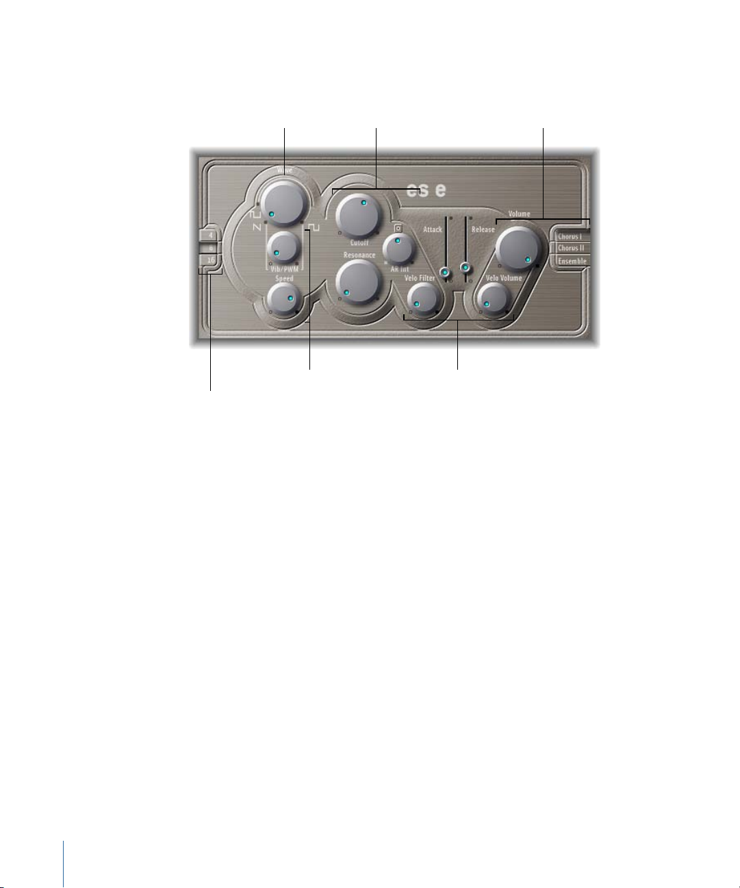
Filter parameters Output parameters
Envelope parametersLFO parameters
Oscillator parameters
Oscillator parameters
Getting to Know the ES E Interface
Before you take a look at the individual parameters of the ES E, this section will familiarize
you with the various elements in the ES E graphical interface.
• Oscillator parameters: The oscillator Wave and Octave parameters are shown in the
area to the left. The oscillator generates the waveforms that form the basis of your
sound. See Using the ES E Oscillators.
• LFO parameters: The LFO parameters (below the oscillator Wave parameter knob) are
used to modulate the sound. See Using the ES E LFO.
• Filter parameters: The section to the right of the Oscillator parameters includes the
Cutoff (Frequency) and Resonance knobs. You use the filter to contour the waveforms
sent from the oscillator. See Using the ES E Filter.
• Envelope parameters: The area to the right of the Filter parameters containsthe Envelope
parameters, which control the level ofthe sound over time. See Using the ES E Envelope.
• Output parameters: The areaat the extreme right houses the Volume knob, responsible
for the main output level, and the Effect parameters. The effects can be used to color
or thicken the sound. See Using the ES E Output Parameters.
• Extended parameters: Not shown in the image, the extended parameters are accessed
by clicking the triangle at the lower left of the interface. These parameters include bend
and tuning functions. See Extended ES E Parameters.
14 Chapter 1 ES E
Page 15
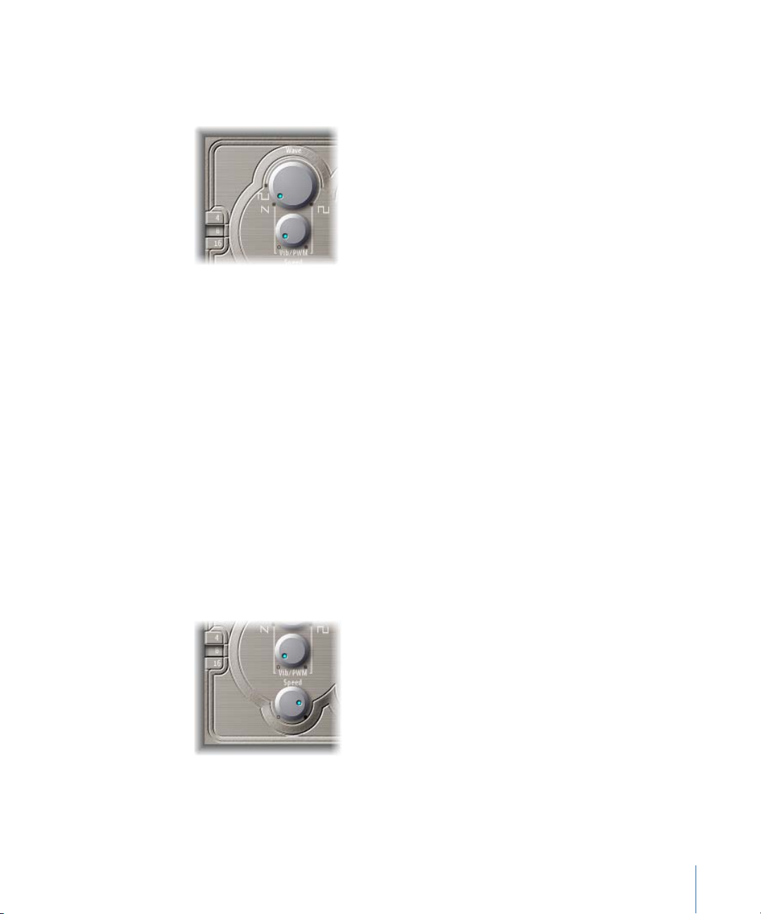
Using the ES E Oscillators
The synthesizer oscillator generates a waveform, which is then sent to other portions of
the synthesizer engine for processing or manipulation.
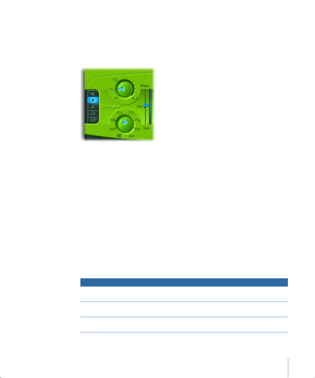
• Wave knob: Selects the waveform of the oscillator, which is responsible for the basic
color of the tone. The leftmost setting of the Wave parameter causes the oscillators to
output sawtooth signals. Across the remaining range, the oscillators output pulse waves,
with the average pulse width being defined by the Wave parameter position.
• 4, 8, 16 buttons: Allow you to switch the pitch in octaves (transpose it up or down). The
lowest setting is 16 feet, and the highest is 4 feet. The use of the term feet to determine
octaves comes from the measurements of organ pipe lengths. The longer (and wider)
the pipe, the deeper the tone.
Using the ES E LFO
The LFO (low frequency oscillator) generates a cyclic waveform that is used to modulate
the ES E waveform. The behavior and effect of the LFO depend on whether a sawtooth
or pulse wave is selected.
• If Wave is set to sawtooth, the LFO modulates the frequency of the waveform, resulting
in a vibrato or siren effect—depending on the LFO speed and intensity.
• If Wave is set to a pulse wave, the LFO modulates the waveform’s pulse width (PWM).
• Vib/PWM knob: Defines the intensity of the LFO modulation.
• Speed knob: Sets the frequency of the LFO modulation.
15Chapter 1 ES E
Page 16
Note: When the pulse width becomes very narrow, the signal sounds as if it is being
interrupted (“breaking up”). Given this potential artifact, set the PWM intensity with
care, and select the Wave parameter’s 12 o’clock position (50% rectangular) for the
pulse width, if you want to achieve the maximum modulation range.
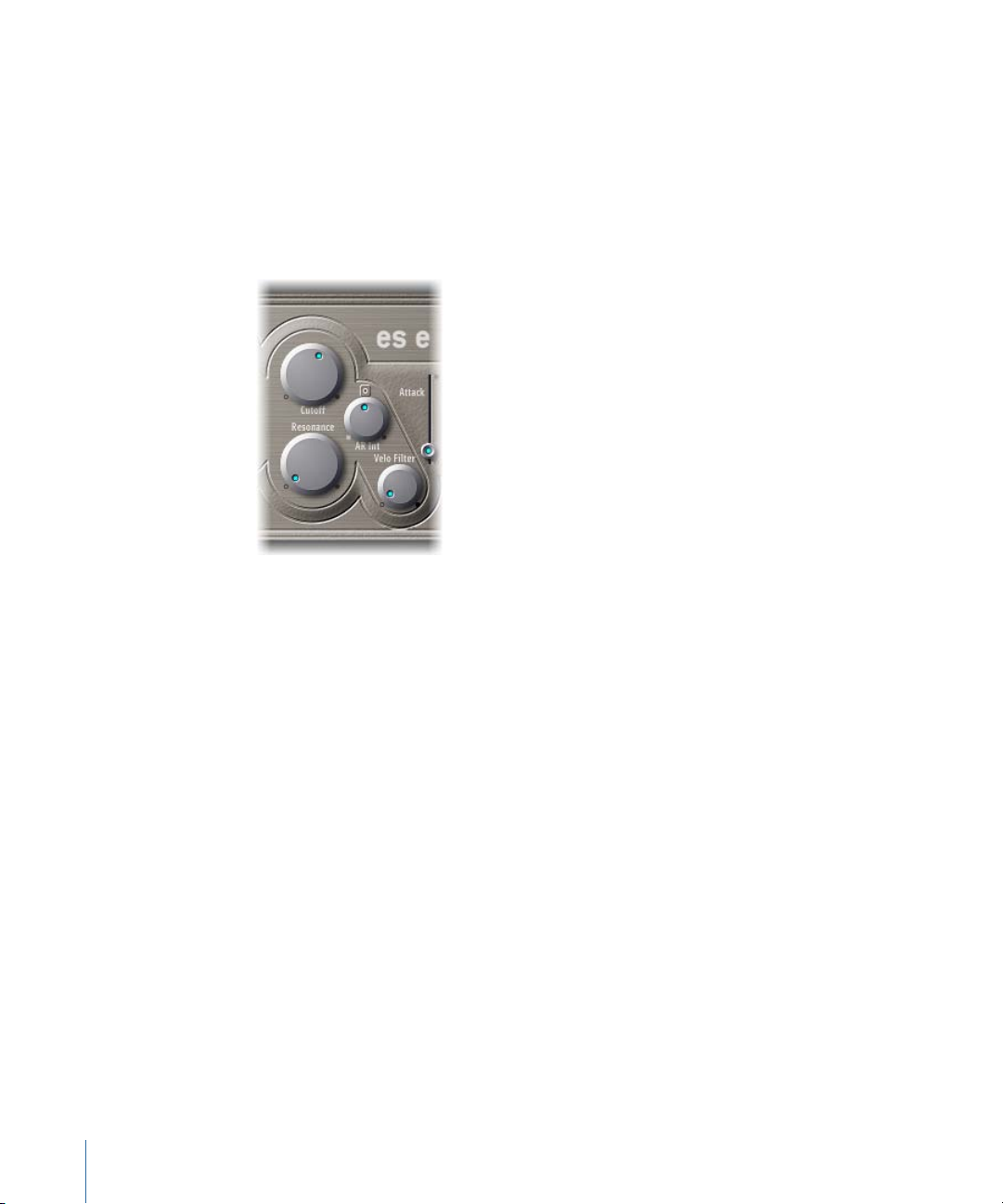
Using the ES E Filter
The ES E includes a lowpass filter that lets you contour the output from the oscillator.
• Cutoff knob: Controls the cutoff frequency of the ES E filter.
• Resonance knob: Boosts or cuts portions of the signal that surround the frequency
defined by the Cutoff parameter.
Note: Increasing the Resonance value results in a rejection of bass (low frequency
energy) when using lowpass filters.
• AR Int knob: The ES E features one simple envelope generator per voice-offering an
Attack and a Release parameter (see Using the ES E Envelope). The AR Int knob defines
the amount (depth) of cutoff frequency modulation applied by the envelope generator.
• VeloFilter knob: Sets the velocity sensitivity of the cutoff frequency modulation applied
by the envelope generator.
Note: This parameter has no effect if AR Int is set to 0.
16 Chapter 1 ES E
Page 17
Using the ES E Envelope
The AR (Attack and Release) envelope affects both the filter cutoff (AR Int) and the level
of the sound over time.
• Attack slider: Determines the time that it takes for the signal to reach the initial, desired
signal level (the sustain level).
• Release slider: Determines the time that it takes for the signal to fall from the sustain
level to a level of zero.
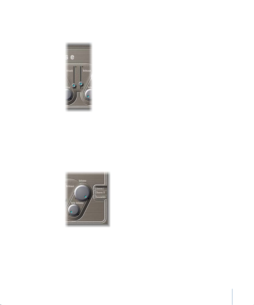
Using the ES E Output Parameters
The ES E output stage consists of the Volume section and the Chorus/Ensemble buttons.
• Volume knob: Sets the overall output level of the ES E.
• Velo Volume knob: Sets the amount (depth) of velocity sensitivity to incoming MIDI
note events. When it is set to higher values, each note is louder, if struck more firmly.
At lower values, the dynamic response is reduced, so that there is little difference when
you play a note pianissimo (soft) or forte (loud/hard).
17Chapter 1 ES E
Page 18

• Chorus I, Chorus II, and Ensemble buttons: Click to switch any of these effect variations
on or off.
• Chorus I and Chorus II are typical chorus effects.
• Chorus II is characterized by a stronger modulation.
• The Ensemble effect employs a more complex modulation routing, creating a fuller
and richer sound.
• If none of the buttons is active, the effects processor is turned off.
Extended ES E Parameters
The ES E offers three additional parameters that are accessed by clicking the disclosure
triangle at the lower left of the interface.
• Pos.Bender Range: Changes the positive (upwards) pitch bend range in semitone steps.
This allows you to use the pitch bend controller of your keyboard to bend the ES E
pitch.
• Neg. Bender Range: The default Neg. Bender Range value is Pos PB (Positive Pitch Bend).
In essence, this means that only positive pitch bend is available. You can adjust the
negative (downwards) pitch bend range in semitone steps-up to 2 octaves (a value of
24).
• Tune: Tunes the entire instrument in cents. A cent is 1/100th of a semitone.
18 Chapter 1 ES E
Page 19

ES M
2
The monophonic ES M is a good starting point if you’re looking for bass sounds that
punch through your mix.
The ES M (ES Mono) synthesizer features an automatic fingered portamento mode, making
bass slides easy. It also provides an automatic filter compensation circuit that delivers
rich, creamy basses, even when using higher resonance values.
The ES M produces sounds using subtractive synthesis. It features an oscillator that
generates harmonically rich waveforms. You subtract (cut, or filter out) portions of these
waveforms, and reshape them, to create new sounds.
If you’re totally new to synthesizers, it might be best to start off with Synthesizer Basics,
which will introduce you to the terminology, and give you a great overview of different
synthesis methods and how they work.
This chapter covers the following:
• Getting to Know the ES M Interface (p. 20)
• Using the ES M Oscillator (p. 21)
• Using the ES M Filter and Filter Envelope (p. 22)
• Using the ES M Level Envelope and Output Controls (p. 23)
• Extended ES M Parameters (p. 23)
19
Page 20
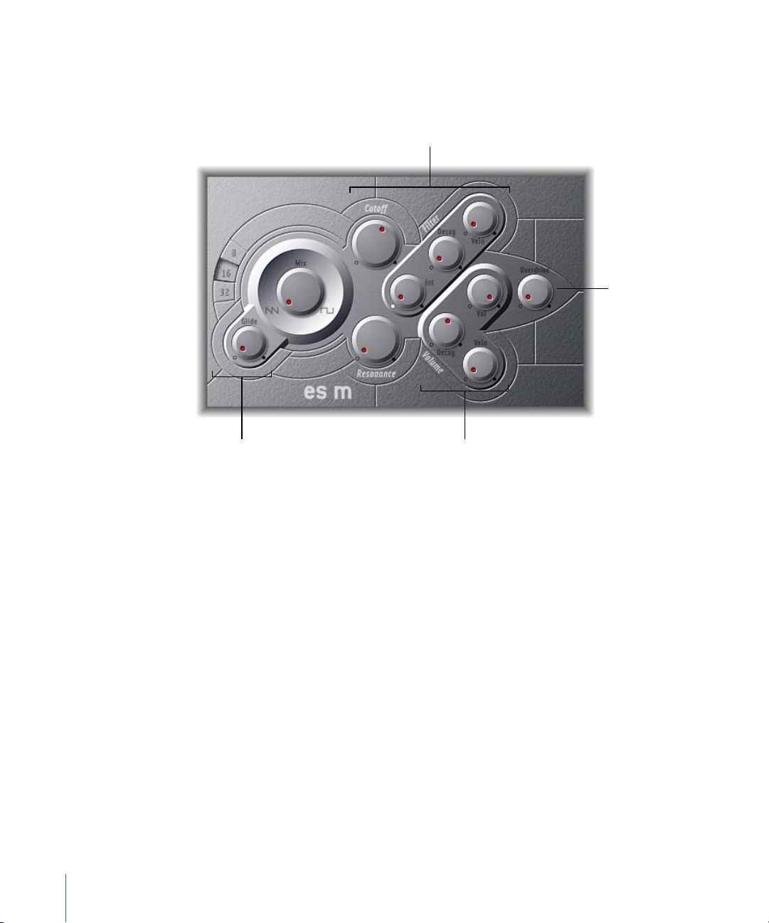
Getting to Know the ES M Interface
Oscillator parameters Output parameters
Filter and Filter Envelope
parameters
Overdrive
Before you take a look at the individual parameters of the ES M, this section will familiarize
you with the various elements in the ES M graphical interface.
• Oscillator parameters: The oscillator Mix and Octave parameters are shown in the area
to the left. The oscillator generates the basic waveforms that form the basis of your
sound. See Using the ES M Oscillator.
• Filter and Filter Envelope parameters: The section to the right of the Oscillator parameters
includes the (Cutoff) Frequency and Resonance knobs. The filter is used to contour the
waveforms sent from the oscillators. The Filter Envelope parameters are found towards
the upper right. These control the filter cutoff over time. See Using the ES M Filter and
Filter Envelope.
• Output parameters: The angle-shaped area to the lower right containsthe Level Envelope
and Output parameters, which control the level of the sound over time. The Overdrive
knob is located near the right edge of the interface, halfway up. The Overdrive can be
used to color or add bite to the sound. See Using the ES M Level Envelope and Output
Controls.
• Extended parameters: Not shown in the image, the extended parameters are accessed
by clicking the triangle at the lower left of the interface. These parameters include bend
and tuning functions. See Extended ES M Parameters.
20 Chapter 2 ES M
Page 21
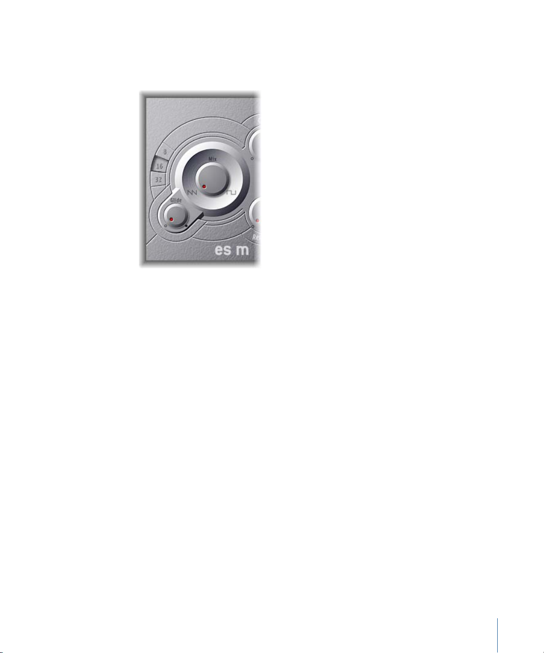
Using the ES M Oscillator
The synthesizer oscillator is used to generate a waveform, which is then sent to other
portions of the synthesizer engine for processing or manipulation.
• Mix knob: Sets the waveform of the oscillator, which is responsible for the basic color
of the tone.
• Setting the Wave parameter all the way to the left causes the oscillators to output
sawtooth signals.
• Setting the Wave parameter all the way to the right outputs a 50% rectangular
wave—which is heard one octave below the sawtooth.
• For any Wave setting between these extreme positions, the oscillator outputs a
crossfaded mix of the two waveforms.
• 8, 16, 32 buttons: Allow you to switch the pitch in octaves (transpose it up or down).
The lowest setting is 32 feet, and the highest is 8 feet. The use of the term feet to
determine octaves comes from the measurements of organ pipe lengths. The longer
(and wider) the pipe, the deeper the tone.
• Glide knob: Determines the speed of the glide (the time it takes to slide between note
pitches). At a value of 0, no glide effect occurs.
Note: The ES M always works in a fingered portamento mode, with notes played in a
legato style resulting in a glide (portamento) from pitch to pitch.
21Chapter 2 ES M
Page 22
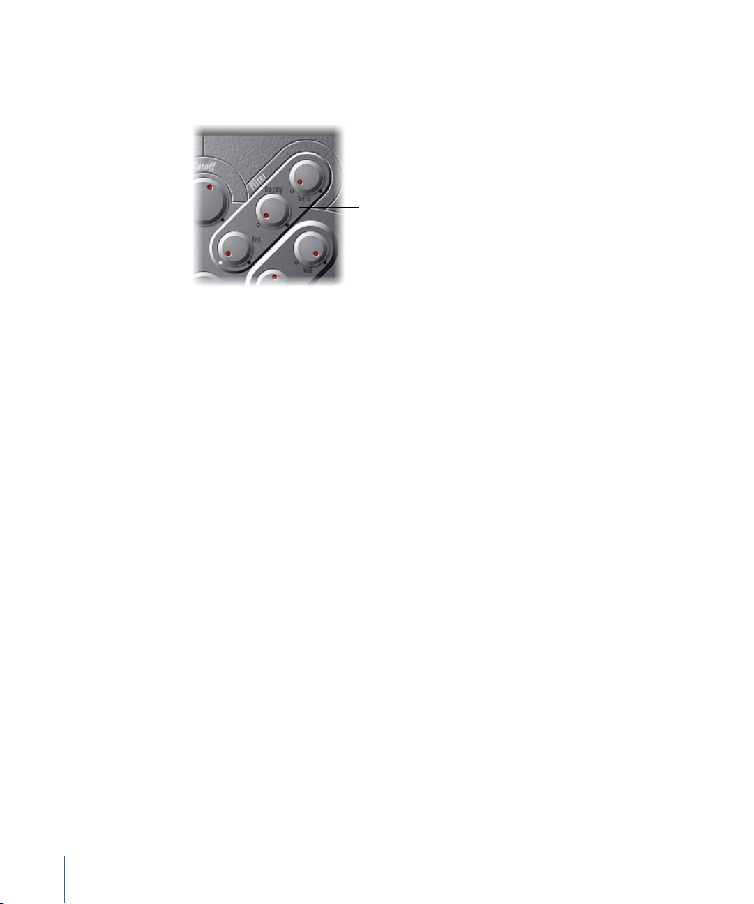
Using the ES M Filter and Filter Envelope
Filter Envelope
parameters
The ES M includes a lowpass filter that lets you contour the output from the oscillator.
The filter features a dedicated envelope.
• Cutoff knob: Controls the cutoff frequency of the ES M filter. Its slope is 24 dB/octave.
• Resonance knob: Boosts or cuts portions of the signal that surround the frequency
defined by the Cutoff parameter.
Note: Increasing the Resonance value results in a rejection of bass (low frequency
energy) when using lowpass filters. The ES M compensates for this side-effect internally,
resulting in a more bassy sound.
• Int knob: Defines the amount (the intensity or depth) of cutoff frequency modulation
applied by the envelope generator.
• Decay knob: Defines the decay time of the filter envelope.
• Velo knob: Sets the velocity sensitivity of the cutoff frequency modulation applied by
the envelope generator.
Note: The Decay and Velo parameters have no effect if Int is set to 0.
22 Chapter 2 ES M
Page 23
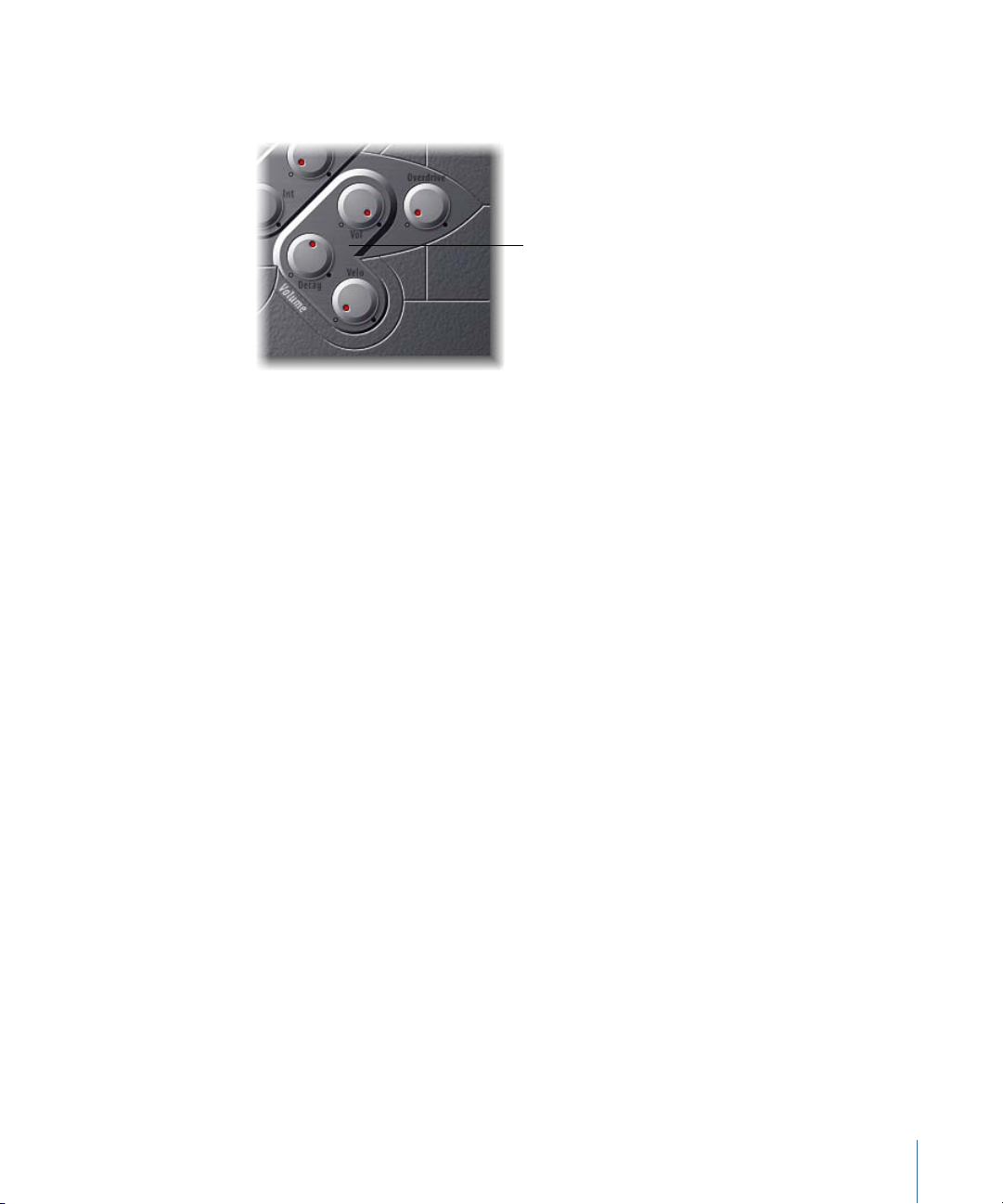
Using the ES M Level Envelope and Output Controls
Level parameters
The output stage of the ES M offers the following parameters.
• Decay knob: Sets the decay time of the dynamic stage. The attack, release, and sustain
times of the synthesizer are internally set to 0.
• Velo knob: Determines the velocity sensitivity of the dynamic stage.
• Vol knob: Sets the master output level of the ES M.
• Overdrive knob: Controls the level of the integrated overdrive effect.
Important: To avoid hurting your ears or damaging your speakers, consider turning
down the Volume level before setting Overdrive to a high value; then turn it up
gradually.
Extended ES M Parameters
The ES M offers three additional parameters that are accessed by clicking the disclosure
triangle at the lower left of the interface.
• Pos.Bender Range: Changes the positive (upwards) pitch bend range in semitone steps.
This allows you to use the pitch bend controller of your keyboard to bend the ES P
pitch.
• Neg. Bender Range: The default Neg. Bender Range value is Pos PB (Positive Pitch Bend).
In essence, this means that only positive pitch bend is available. You can adjust the
negative (downwards) pitch bend range in semitone steps-up to 2 octaves (a value of
24).
• Tune: Tunes the entire instrument in cents. A cent is 1/100th of a semitone.
23Chapter 2 ES M
Page 24

Page 25

ES P
3
The ES P emulates classic polyphonic synthesizers of the 1980s.
The 8-voice ES P (ES Poly) is a versatile instrument that is capable of producing a huge
variety of useful musical sounds. The creation of classic analog synthesizer brass sounds
is just one of its many strengths.
The ES P produces sounds using subtractive synthesis. It features an oscillator that
generates harmonically rich waveforms. You subtract (cut, or filter out) portions of these
waveforms, and reshape them, to create new sounds.
If you’re totally new to synthesizers, it might be best to start off with Synthesizer Basics,
which will introduce you to the terminology, and give you a great overview of different
synthesis methods and how they work.
This chapter covers the following:
• Getting to Know the ES P Interface (p. 26)
• Using the ES P Oscillators (p. 27)
• Using the ES P LFO (p. 27)
• Using the ES P Filter (p. 28)
• Using the ES P Envelope and Level Controls (p. 29)
• Using the Integrated ES P Effects (p. 30)
• Extended ES P Parameters (p. 30)
25
Page 26
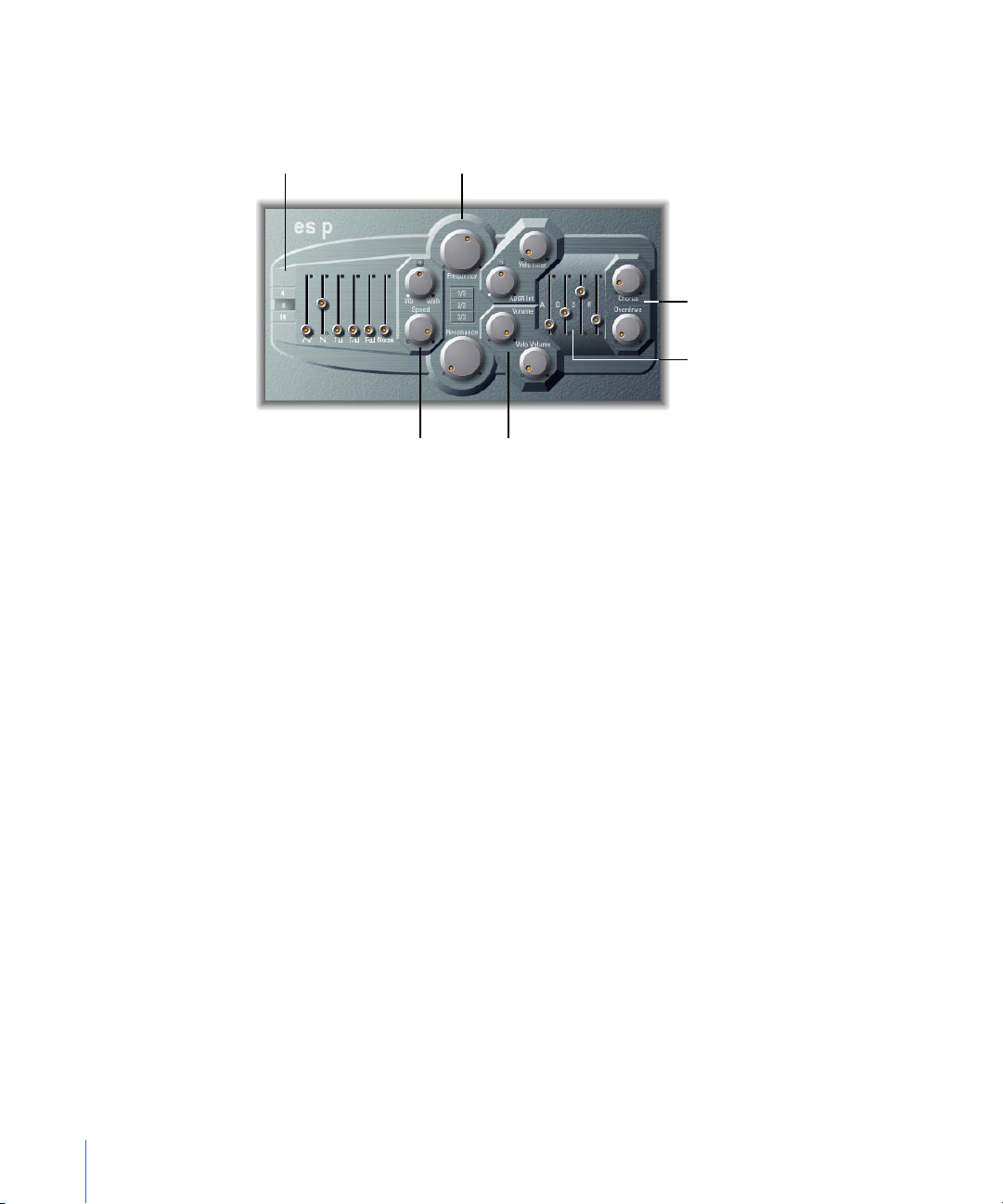
Filter parameters
Effect parameters
Envelope parameters
Level parametersLFO parameters
Oscillator parameters
Getting to Know the ES P Interface
Before you take a look at the individual parameters of the ES P, this section will familiarize
you with the various elements in the ES P graphical interface.
• Oscillator parameters: The Oscillator sliders are shown in the area to the left. The Octave
parameters are also found in this section. The oscillators generate the basic waveforms
that form the basis of your sound. See Using the ES P Oscillators.
• LFO parameters: The LFO parameters (to the right of the Oscillator parameters) are used
to modulate the sound. See Using the ES P LFO.
• Filter parameters: The vertical column in the center includes the (Cutoff) Frequency and
Resonance knobs and the Key Follow buttons. The filter is used to contour the
waveforms sent from the oscillators. See Using the ES P LFO.
• Envelope and Level parameters: The area to the right of the Filter parameters contains
the Envelope and Level parameters, which control the level of the sound over time.
See Using the ES P Envelope and Level Controls.
• Effect parameters: The area at the extreme right contains the Chorus and Overdrive
parameters. These can be used to color or thicken the sound. See Using the Integrated
ES P Effects.
• Extended parameters: Not shown in the image, the extended parameters are accessed
by clicking the triangle at the lower left of the interface. These parameters include bend
and tuning functions. See Extended ES P Parameters.
26 Chapter 3 ES P
Page 27
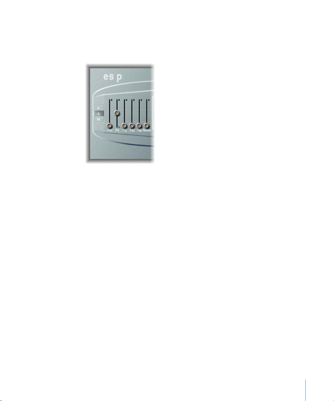
Using the ES P Oscillators
The ES P features several oscillators that output different waveforms. These signals can
be mixed together—at different levels—providing countless variations of the raw material
used for your sounds.
• Oscillator sliders: Set the level of the waveforms output by the oscillators.
• In addition to triangular, sawtooth, and rectangular waves, the rectangular waves of
two sub-oscillators are also available. The left sub-oscillator fader is one octave lower
than the main oscillators, and the right sub-oscillator fader is two octaves lower. Use
these to fatten up the sound.
• The pulse width of all rectangular waves is fixed at 50%.
• The rightmost fader adds white noise to the mix. This is the raw material for classic
synthesizer sound effects, such as ocean waves, wind, and helicopters.
• 4, 8, 16 buttons: Allow you to switch the pitch in octaves (transpose it up or down). The
lowest setting is 16 feet, and the highest is 4 feet. The use of the term feet to determine
octaves comes from the measurements of organ pipe lengths. The longer (and wider)
the pipe, the deeper the tone.
Using the ES P LFO
The ES P features an LFO (low frequency oscillator), which can do either of the following:
• Modulate the frequency of the oscillators, resulting in a vibrato.
27Chapter 3 ES P
Page 28
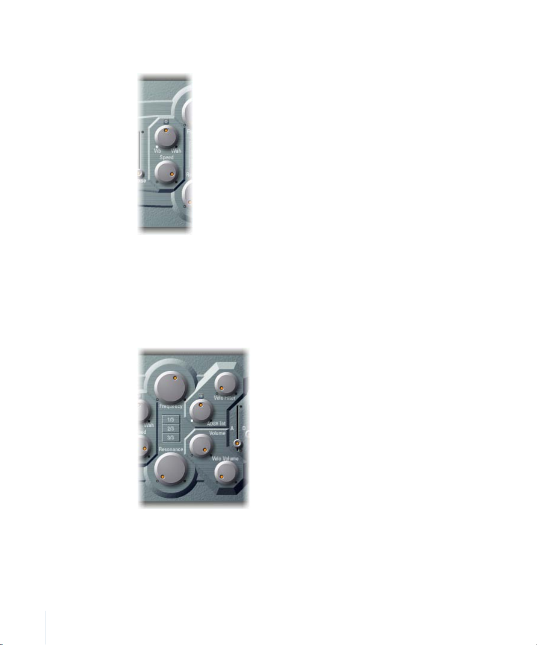
• Modulate the cutoff frequency of the dynamic lowpass filter, resulting in a wah wah
effect.
• Vib/Wah knob: Turn to the left to set a vibrato; turn to the right to cyclically modulate
the filter.
• Speed knob: Sets the rate of the vibrato or cutoff frequency modulation.
Using the ES P Filter
The ES P includes a lowpass filter that lets you contour the output from the oscillator.
• Frequency knob: Controls the cutoff frequency of the ES P’s lowpass filter.
• Resonance knob: Boosts/cuts portions of the signal that surround the frequency defined
by the Frequency knob.
28 Chapter 3 ES P
Page 29

Note: Increasing the Resonance value results in a rejection of bass (low frequency
energy) when using lowpass filters. The ES P compensates for this side-effect internally,
resulting in a more bassy sound.
• 1/3, 2/3, 3/3 (Key Follow) buttons: The cutoff frequency can be modulated by MIDI note
number (keyboard position); you may know this parameter as keyboard follow on other
synthesizers. Enable one of the 1/3, 2/3, 3/3 buttons to choose one-third, two-thirds,
or full-keyboard follow. If no button is active, the key you strike won’t affect the cutoff
frequency. This makes the lower notes sound relatively brighter than the higher ones.
If 3/3 is chosen, the filter follows the pitch, resulting in a constant relationship between
cutoff frequency and pitch. This is typical of many acoustic instruments where higher
notes sound both brighter in tone and higher in pitch.
• ADSR Int knob: Defines the amount (depth) of cutoff frequency modulation applied by
the envelope generator (see Using the ES P Envelope and Level Controls).
• VeloFilter knob: Sets the velocity sensitivity of the cutoff frequency modulation applied
by the envelope generator. The main envelope generator (ADSR) modulates the cutoff
frequency over the duration of a note. The intensity of this modulation can respond to
velocity information. If you play pianissimo (velocity = 1), the modulation is minimal.
If you strike with the hardest fortissimo (velocity = 127), the modulation is more intense.
Using the ES P Envelope and Level Controls
The ES P features an ADSR envelope that affects both the filter cutoff (ADSR Int) and the
level of the sound over time. This section also covers the master level control parameters.
• Attack slider: Determines the time it takes for the signal to reach the initial, desired
signal level (the sustain level).
• Decay slider: Determines the time it takes for the signal to fall from the attack level to
the sustain level.
29Chapter 3 ES P
Page 30
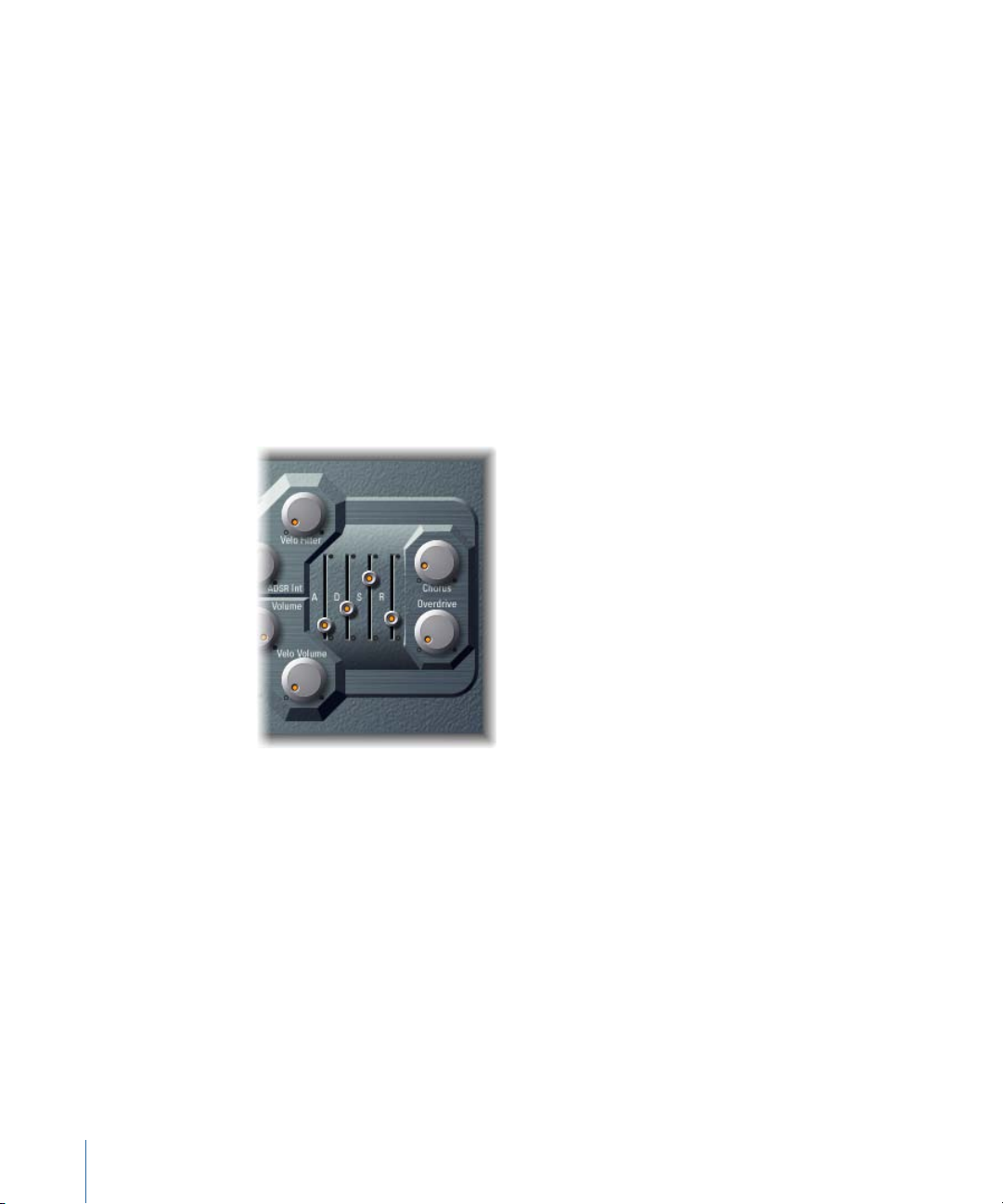
• Sustain slider: Determines the desired signal level (the sustain level).
• Release slider: Determines the time it takes for the signal to fall from the sustain level
to a level of zero.
• Volume knob: Sets the overall output level of the ES P.
• Velo Volume knob: Sets the amount (depth) of velocity sensitivity to incoming MIDI
note events. When set to higher values, each note is louder if struck more firmly. At
lower values, the dynamic response is reduced, so that there is little difference when
you play a note pianissimo (soft) or forte (loud/hard).
Using the Integrated ES P Effects
The ES P offers integrated stereo chorus and overdrive effects. These are based on similar
effects processors found in the affordable Japanese synthesizers of the 1980s—which
the ES P, itself, emulates.
• Chorus knob: Sets the intensity (depth) of the integrated chorus effect.
• Overdrive knob: Determines the overdrive/distortion level of the ES P output.
Important: To avoid hurting your ears or damaging your speakers, consider turning
down the Volume level before setting Overdrive to a high value; then turn it up
gradually.
Extended ES P Parameters
The ES P offers three additional parameters that are accessed by clicking the disclosure
triangle at the lower left of the interface.
• Pos.Bender Range: Changes the positive (upwards) pitch bend range in semitone steps.
This allows you to use the pitch bend controller of your keyboard to bend the ES P
pitch.
30 Chapter 3 ES P
Page 31

• Neg. Bender Range: The default Neg. Bender Range value is Pos PB (Positive Pitch Bend).
In essence, this means that only positive pitch bend is available. You can adjust the
negative (downwards) pitch bend range in semitone steps-up to 2 octaves (a value of
24).
• Tune field: Tunes the entire instrument in cents. A cent is 1/100th of a semitone.
31Chapter 3 ES P
Page 32

Page 33

ES1
4
The ES1 emulates the circuits of analog synthesizers in a simple, streamlined interface.
The ES1 uses a method of synthesis called subtractive synthesis. It features an oscillator
and sub-oscillator that generate harmonically rich waveforms. You subtract—cut, or filter
out—portions of these waveforms and reshape them to create new sounds. The ES1’s
tone-generation system also provides flexible modulation options that make it easy to
create punchy basses, atmospheric pads, biting leads, and sharp percussion.
If you’re totally new to synthesizers, it might be best to start off with Synthesizer Basics,
which will introduce you to the terminology and give you a great overview of different
synthesis systems and how they work.
This chapter covers the following:
• Getting to Know the ES1 Interface (p. 34)
• Using the ES1 Oscillators (p. 35)
• Using the ES1 Filter Parameters (p. 37)
• Using the ES1 Amplifier Parameters (p. 38)
• Using the ES1 Envelope Parameters (p. 39)
• Modulating the Sound of the ES1 (p. 41)
• Adjusting Global ES1 Parameters (p. 44)
• ES1 MIDI Controller List (p. 45)
33
Page 34

Getting to Know the ES1 Interface
Oscillator parameters Filter parameters Amplifier parameters
Global parameters
Modulation parameters
Envelope parameters
Before you take a look at the individual parameters of the ES1, this section will familiarize
your with the various elements that constitute the ES1’s graphical interface, which is
broken down into six main areas.
• Oscillator parameters: Shown to the left, the oscillators generate the basic waveforms
that form the basis of your sound. See Using the ES1 Oscillators. A number of related
parameters that directly influence the overall sound, such as Tune, are found in the
Global Parameters section of the interface. See Adjusting Global ES1 Parameters.
• Filter parameters: These include the circular Filter area, and Drive and Key scaling
parameters. You use the filter to contour the waveforms sent from the oscillators. See
Using the ES1 Filter Parameters.
• Amplifier parameters: The area to the right contains the Amplifier parameters. See Using
the ES1 Amplifier Parameters.
• Envelope parameters: The ADSR sliders in the lower-right corner of the ES1 can be used
to control both filter cutoff and the amplifier level over time. See Using the ES1 Envelope
Parameters.
• Modulation parameters: The dark green/gray area houses the modulation sources,
modulation router, modulation envelope, and amplitude envelope, which you can use
to modulate the sound in a number of ways. See Modulating the Sound of the ES1.
• Global parameters: Global sound control parameters are located on the bottom
green/gray strip. This is where you can assign and adjust global tuning, activate the
in-built chorus, and more. The chorus can be used to color or thicken the sound. See
Adjusting Global ES1 Parameters.
34 Chapter 4 ES1
Page 35
Using the ES1 Oscillators
The ES1features a primary oscillator and a sub-oscillator. The primary oscillator generates
a waveform, which is then sent to other parts of the synthesizer for processing or
manipulation. The sub-oscillator generates a secondary waveform one or two octaves
below that of the primary oscillator.
• Wave knob: Selects the waveform of the primary oscillator, which is responsible for the
basic color of the tone. See Setting ES1 Oscillator Waveforms.
• Mix slider: Defines the level relationship between the primary and sub-oscillator signals.
When the sub-oscillator is switched off, its output is completely removed from the
signal path.
• Sub knob: The sub-oscillator generates square, pulse, and white-noise waveforms. It
also allows you to route a side chain signal through the ES1 synthesizer engine (see
Using the ES1 Sub-Oscillator).
• 2, 4, 8, 16, 32 buttons: Transpose the pitch of the oscillators up or down by octaves. The
lowest setting is 32 feet, and the highest is 2 feet. The use of the term feet to determine
octaves comes from the measurements of organ pipe lengths. The longer and wider
the pipe, the deeper the tone (for a description of the global Tune parameters, see
Adjusting Global ES1 Parameters).
Setting ES1 Oscillator Waveforms
The following table outlines how the oscillator waveform affects your synthesizer sound.
CommentsBasic toneWaveform
Warm and evenSawtooth
Triangle
sawtooth
Hollow and “woody” soundingSquare
Useful for strings, pads, bass, and
brass sounds
Useful for flutes, padsSweet sounding, softer than
Useful for basses, clarinets, and
oboes
35Chapter 4 ES1
Page 36

CommentsBasic toneWaveform
“Nasal” soundingPulse
Great forreed instruments, synth
blips, basses
Using Pulse Width Modulation in the ES1
You can freely set any pulse width in-between the square wave and pulse wave symbols
of the Wave knob. The pulse width can also be automatically modulated in themodulation
section (see Using the ES1 Router). Modulating the pulse width with a slowly cycling LFO,
for example, allows periodically mutating, fat bass sounds.
Using the ES1 Sub-Oscillator
The sub-oscillator provides the following waveform options:
• A square wave that plays one or two octaves below the frequency of the primary
oscillator.
• A pulse wave that plays two octaves below the frequency of the primary oscillator.
• Variations of these waveforms with different mixes and phase relationships. Their use
results in different sounds.
• White noise which is useful for creating percussion sounds, as well as wind, surf, and
rain sounds.
• You can also completely disable the sub-oscillator by choosing OFF.
Processing Side Chain Signals Through the ES1
The sub-oscillator of the ES1 allows you to run an external channel strip signal through
the ES1 synthesizer engine, by using a side chain.
To process a channel strip signal through the ES1 synthesizer engine
1 Set the Sub knob to EXT.
2 Choose the side chain source channel strip from the Side Chain menu at the top of the
plug-in window.
36 Chapter 4 ES1
Page 37

Using the ES1 Filter Parameters
This section outlines the filter parameters of the ES1.
• Cutoff slider: Controls the cutoff frequency of the ES1’s lowpass filter.
• Resonance slider: Cuts or boosts the portions of the signal that surround the frequency
defined by the Cutoff parameter. Boost can be set so intensively that the filter begins
to oscillate by itself (see Driving the ES1 Filter to Self-Oscillation).
Tip: You can simultaneously adjust the cutoff frequency and resonance parameters by
dragging vertically (cutoff) or horizontally (resonance) on the word Filter, found between
the Slope buttons.
• Slope buttons: The lowpass filter offers four different slopes of band rejection above
the cutoff frequency. The four settings are arranged clockwise from the top left, as
follows:
• 24 dB classic: Mimics the behavior of a Moog filter. Turning up the resonance results
in a reduction of the low end of the signal.
• 24 dB fat: Compensates for the reduction of low frequency content caused by high
Resonance values. This resembles the behavior of an Oberheim filter.
• 12 dB: Provides a soft, smooth sound which is reminiscent of the early Oberheim
SEM.
• 18 dB: Tends to resemble the filter sound of Roland’s TB-303.
• Drive slider: An input level control, which allows you to overdrive the filter. Use it to
change the behavior of the Resonance parameter, which will eventually distort the
sound of the waveform.
• Key slider: Controls how strongly the keyboard pitch (the note number) modulates the
filter’s cutoff frequency:
• If Key is set to zero, the cutoff frequency won’t change, no matter which key you
strike. This makes the lower notes sound relatively brighter than the higher ones.
37Chapter 4 ES1
Page 38

• If Key is set to maximum, the filter follows the pitch, resulting in a constant relationship
between cutoff frequency and pitch. This mirrors the properties of many acoustic
instruments where higher notes sound both brighter in tone and higher in pitch.
• ADSR via Vel slider: Determines how note velocity affects the filter cutoff frequency
modulation—caused by the envelope generator (see Using the ES1 Envelope
Parameters).
Driving the ES1 Filter to Self-Oscillation
You can make the ES1 filter output a sine wave by following the steps below. This will
allow you to “play” the filter-generated sine wave with the keyboard.
To output a sine wave from the filter
1 Switch the Sub knob to OFF.
2 Move the Mix slider to the very bottom (Sub).
3 Turn the Resonance knob to the maximum position.
Using the ES1 Amplifier Parameters
The parameters in the ES1 Amplifier section allow you to fine-tune the behavior of your
sound’s level. These are separate from the global Out Level parameter, found on the strip
at the bottom of the interface, and which acts as the ES 1’s master volume (see Adjusting
Global ES1 Parameters).
• Level via Vel slider: Determines how note velocity affects the synthesizer level-set by
the global Out Level parameter. The slider’s upper arrow indicates the level when you
play fortissimo. The lower arrow indicates the level when you play pianissimo
(velocity = 1). The greater the distance between the arrows (indicated by the blue bar),
the more the volume is affected by incoming velocity messages. You can simultaneously
adjust the modulation range and intensity by dragging the blue bar-between the
arrows-and moving both arrows at once.
38 Chapter 4 ES1
Page 39

• Amplifier Envelope Selector buttons: The AGateR, ADSR, and GateR buttons define which
ADSR via Vel slider
of the ADSR envelope generator controls have an effect on the amplifier envelope (see
Using the Envelope to Control the ES1 Amplifier).
Using the ES1 Envelope Parameters
The ES1 features an attack, decay, sustain, and release (ADSR) envelope that can shape
the filter cutoff and the level of the sound over time.
• Attack slider: Determines the amount of time that it takes for the envelope to reach
the initial, desired level.
• Decay slider: Determines how long it takes for the envelope to fall to the sustain level,
following the initial attack time.
• Sustain slider: Sets the sustain level, which is held until the keyboard key is released.
• Release slider: Determines the length of time that it takes the envelope to fall from the
sustain level to a level of zero.
Using the Envelope to Control ES1 Cutoff Frequency
The envelope generator modulates the filter cutoff frequency over the duration of a note.
The intensity of this modulation—and how it responds to velocity information—is set
by the ADSR via Vel slider arrows (in the Filter Parameters section).
39Chapter 4 ES1
Page 40

The modulation range is determined by the two arrows. The minimum amount of
Amplifier Envelope
Selector buttons
modulation is indicated by the lower arrow. The upper arrow indicates the maximum
amount of modulation. The blue bar between the arrows shows the dynamic range of
this modulation. You can simultaneously adjust the modulation range and intensity by
dragging the blue bar and moving both arrows at once.
Tip: If you’re unfamiliar with these parameters, set the Cutoff to a low value, Resonance
to a high value, and move both of the ADSR via Vel arrows upwards. Constantly strike a
note onthe keyboard while changing the arrows to discover how theseparameters work.
Using the Envelope to Control the ES1 Amplifier
The AGateR, ADSR, and GateR buttons (in the Amplifier Parameter section) define which
of the ADSR envelope generator controls affect the amplifier envelope. All ADSR
parameters remain active for the filter.
The letters A, D, S, and R refer to the attack, decay, sustain, and release phases of the
envelope (see Using the ES1 Envelope Parameters). Gate refers to a control signal used
in analog synthesizers that tells an envelope generator that a key is pressed. As long as
an analogsynthesizer’s key is pressed, the gate signal maintains a constant voltage. When
Gate is used as a modulation source in the voltage-controlled amplifier (instead of the
envelope itself), it creates an organ type envelope without any attack, decay, or release-an
even, sustained sound.
In the ES1, the Amplifier Envelope selector buttons have the following effect on played
notes:
• AGateR: The Attack and Release sliders of the ADSR Envelope control the attack and
release phases of the sound. In-between these phases, the Gate control signal is used
to maintain a constant level, while the note is held. As soon as you release the key, the
release phase begins. The Decay and Sustain sliders of the ADSR Envelope have no
impact on the sound’s level.
• ADSR: This is the standard operating mode of most synthesizers, where the level of the
sound over time is completely controlled by the ADSR Envelope.
40 Chapter 4 ES1
Page 41

• GateR: The Gate control signal is used to maintain a constant level, while the note is
Modulation EnvelopeRouterLFO parameters
Parameter target buttons
held. As soon as you release the key, the release phase begins. The Attack, Decay and
Sustain sliders of the ADSR Envelope have no impact on the sound’s level.
Modulating the Sound of the ES1
The ES1 offers a number of simple, yet flexible, modulation routing options. Modulation
is used to add animation to your sound over time, making it more interesting, lively, or
realistic. A good example of this type of sonic animation is the vibrato used by orchestral
string players.
• LFO parameters: Used to modulate other ES1 parameters. See Using the ES1 LFO.
• Router: Allows you to choose which ES1 parameters are modulated. See Using the ES1
Router below.
• Modulation Envelope: A dedicated modulation control source, it can directly control
other ES1 parameters, or it can control the LFO level. See Using the ES1 Mod Envelope.
Using the ES1 Router
The router is used to determine which of the ES1 parameters are modulated by the LFO
(see Using the ES1 LFO) and/or by the Modulation Envelope (see Using the ES1 Mod
Envelope). The parameter target buttons in the left column enable LFO modulation, and
the ones in the right column set the target for the Modulation Envelope.
• Pitch buttons: Turn on to modulate the pitch—the frequency—of the oscillators.
• Pulse Width buttons: Turn on to modulate the pulse width of the pulse wave.
41Chapter 4 ES1
Page 42

• Mix buttons: Turn on to modulate the mix between the primary and sub-oscillators.
• Cutoff buttons: Turn on to modulate the cutoff frequency of the filter.
• Resonance buttons: Turn on to modulate the resonance of the filter.
• Volume buttons: Turn on to modulate the main volume.
• Filter FM button (modulation envelope only): Turn on to use the triangle wave of the
oscillator to modulate the filter cutoff frequency. This modulation can result in a
pseudo-distortion of the sound, or it can create metallic, FM-style sounds. The latter
occurs when the only signal you can hear is the self-oscillation of the resonating filter
(see Driving the ES1 Filter to Self-Oscillation).
• LFO Amp (modulation envelope only): Turn on to modulate the overall amount of LFO
modulation.
Using the ES1 LFO
The LFO (low frequency oscillator) generates an adjustable, cyclic waveform that can be
used to modulate other ES1 parameters (as discussed in Using the ES1 Router).
• Wave knob: Sets the LFO waveform. You can choose from triangle, ascending and
descending sawtooth, square wave, sample & hold (random), and a lagged, smoothly
changing random wave. Each of these waveforms cycles in its own way, providing
different types of modulation. You can also assign a side chain signal as a modulation
source (EXT). Choose the side chain source channel strip from the Side Chain menu at
the top of the plug-in window.
• Rate slider and field: Defines the speed—the frequency—of the LFO waveform cycles.
• If you set values to the left of zero, the LFO phase is locked to the tempo of the host
application—with phase lengths adjustable between 1/96 bar and 32 bars. If you
select values to the right of zero, the LFO phase runs freely.
• When set to zero, the LFO outputs at a constant and full level, which allows you to
manually control the LFO speed with your keyboard’s modulation wheel. This could
be useful, for example, if you wanted to change the pulse width by moving your
keyboard’s modulation wheel. The pulse width would be chosen as the LFO
modulation target (left router column), and the modulation intensity range would
be determined by the Int via Whl setting.
42 Chapter 4 ES1
Page 43

• Int via Whl slider: The upper arrow defines the intensity of the LFO modulation if the
modulation wheel (MIDI controller 1) is set to its maximum value. The lower arrow
defines the amount of LFO modulation if the modulation wheel is set to zero. The
distance between the arrows—shown by a green bar—indicates the range of your
keyboard’s modulation wheel. You can simultaneously adjust the modulation range
and intensity by dragging the green bar, thus moving both arrows at once. Note that
as you do so, the arrows retain their relative distance from each other.
Using the ES1 Mod Envelope
The modulation envelope allows you to set a percussive type of decay envelope by
choosing low values, or attack type envelopes with high values.
• Form slider and field: Allows you to fade in (attack) or fade out (decay) the modulation.
When set to the full position, the modulation envelope is turned off.
• Int via Vel slider: The top arrow controls the upper modulation intensity setting for the
modulation envelope—if you strike a key with the hardest fortissimo (velocity = 127).
The bottom arrow controls the lower modulation intensity setting for the modulation
envelope—if you strike a key with the softest pianissimo (velocity = 1). The green bar
between the arrows displays the impact of velocity sensitivity on the intensity of the
modulation envelope. You can simultaneously adjust the modulation range and intensity
by dragging the green bar, thus moving both arrows at once. Note that as you do so,
the arrows retain their relative distance from each other.
Controlling ES1 Parameters and the LFO with the Mod Envelope
The Modulation Envelope can directly modulate the parameter chosen in the router. It
essentially determines the time it takes for the modulation to fade in or fade out. At its
center position, which can be accessed by clicking the middle mark, the modulation
intensity is static—no fade in or fade out will occur. When set to its full value, it delivers
a constant level.
To modulate a parameter with velocity
1 Select a modulation destination (Pulse Width, for example).
2 Set Form to full, and adjust the Int via Vel parameter as needed.
This results in a velocity-sensitive modulation of the oscillator pulse width.
More interestingly, the Modulation Envelope can directly control the LFO level when you
click the LFO Amplitude button in the right column of the router.
43Chapter 4 ES1
Page 44

To fade the LFO modulation in or out
Choose a positive Form value (towards attack) to fade in the LFO modulation. The higher
µ
the value, the longer it takes for you to hear the modulation.
Choose a negative value (towards decay) to fade out the LFO modulation. The lower the
µ
value (closer to full), the shorter the fade out time is.
LFO control with envelopes is most often used for delayed vibrato, which is a technique
many instrumentalists and singers employ to intonate longer notes.
To set up a delayed vibrato
1 Position the Form parameter toward the right (attack).
2 Choose Pitch as the LFO target (left column).
3 Choose the triangular wave as the LFO waveform.
4 Select an LFO Rate of about 5 Hz.
5 Set the upper Int via Wheel arrow to a low value, and the lower arrow to 0.
Adjusting Global ES1 Parameters
This section covers global parameters that affect the overall sound, or behavior, of the
ES1. The global parameters are found in the strip that spans the lower edge of the ES1
interface. The Glide slider is displayed above the left end of the strip.
• Glide slider: Defines the amount of time it takes to slide between the pitches of each
triggered note. The Glide trigger behavior depends on the value chosen for the Voices
parameter (see below).
• Tune field: Tunes the entire instrument in cents. A cent is 1/100th of a semitone.
• Analog field: Slightly alters the pitch of each note, and the cutoff frequency, in a random
fashion. This emulates the random oscillator detuning and filter fluctuations that can
occur in polyphonic analog synthesizers—due to heat and age.
• Voices field: Sets the maximum number of notes that can be played simultaneously.
Each ES1 instance offers a maximum of 16 voices. Fewer played voices require less CPU
power.
• Bender Range field: Changes the sensitivity of the pitch bender. Adjustments are in
semitone steps.
• Neg Bender Range slider (Extended Parameters area): Adjusts the negative (downwards)
pitch bend range in semitone steps. The default value is Pos PB (Positive Pitch Bend),
which essentially means that there is no downward pitch bend available. Click the small
triangle at the lower left of the ES1 interface to access the Extended parameters area.
44 Chapter 4 ES1
Page 45

• Chorus field: The ES1 offers two classic stereo chorus effects and one ensemble effect.
• Off deactivates the in-built chorus circuit.
• C1 and C2 are typical chorus effects. C2 is a variation of C1 and is characterized by a
stronger modulation.
• Ens (Ensemble) employs a more complex modulation routing, creating a fuller and
richer sound.
• Out Level field: Controls the master volume of the ES1.
Using the ES1 Analog Parameter
When the Analog parameter is set to a value of zero, the oscillator cycle start points of
all triggered voices are synchronized. This may be useful for percussive sounds, when
you want to achieve a sharper attack characteristic.
Use of Analog values higher thanzero allows the oscillators of all triggered voices to cycle
freely. Use higher values if you’re aiming for a warm, analog type of sound—where subtle
sonic variations occur for each triggered voice.
Using the Voices Parameter in the ES1
When the Voices parameter is set to Legato, the ES1 behaves like a monophonic
synthesizer—with single trigger and fingered portamento engaged. This means that if
you play legato, a portamento will occur (the portamento time is defined by the Glide
slider). If you release each key before pressing a new one, the envelope will not be
triggered by the new note, and there will be no portamento.
Tip: You can use this feature to create pitch bend effects—without touching the pitch
bender—so make sure you select a higher Glide value when using the Legato setting.
ES1 MIDI Controller List
The ES1 responds to the following MIDI continuous controller numbers (CC).
Parameter nameController number
Oscillator pitch buttons12
Oscillator waveform13
Mix slider14
Waveform of sub-oscillator15
Drive slider16
Cutoff slider17
Resonance slider18
Slope buttons19
ADSR via Vel:lower slider20
45Chapter 4 ES1
Page 46

Parameter nameController number
ADSR via Vel:upper slider21
Attack slider22
Decay slider23
Sustain slider24
Release slider25
Key slider26
Amplifier Envelope Selector buttons27
Level via Velocity:lower slider28
Level via Velocity:upper slider29
Chorus parameter30
Modulation envelope target31
Modulation Envelope form slider102
Modulation envelope:Int via Vel parameter:lower slider103
Modulation envelope:Int via Vel parameter:upper slider104
LFO rate105
LFO waveform106
LFO modulation target107
LFO:Int via Whl:lower slider108
LFO:Int via Whl:upper slider109
Glide slider110
Tune parameter111
Analog parameter112
Bender Range parameter113
Out Level parameter114
Voices parameter115
46 Chapter 4 ES1
Page 47

ES2
5
The ES2 synthesizer combines a powerful tone generation system with extensive
modulation features. It seamlessly blends subtractive synthesis and elements of FM and
wavetable synthesis methods to generate an extraordinary variety of sounds. This makes
it the perfect synthesizer for the creation of powerful pads, evolving textures, rich basses,
or synthetic brass.
The three oscillators of the ES2 provide classic analog synthesizer waveforms (including
noise) and 100 single-cycle waveforms, known as Digiwaves. This raw material forms the
basis for sounds that range from fat analog to harsh digital sounds, or hybrids of the two.
You can also cross-modulate oscillators, making it easy to create FM-style sounds. Further
options include the ability to synchronize and ring-modulate the oscillators, or to mix a
sine wave directly into the output stage, to thicken the sound.
The ES2 features a flexible modulation router that offers up to ten simultaneous
(user-defined) modulation routings. These can be used alongside a number of hard-wired
routings. Further modulation options include the unique Planar Pad—which provides
control of two parameters on a two-dimensional grid. The Planar Pad itself can be
controlled by the sophisticated Vector Envelope. This is a multipoint, loop-capable
envelope that makes it easy to create complex, evolving sounds.
Lastly, Distortion, Chorus, Phaser, and Flanger effects are built into the ES2.
If you’re totally new to synthesizers, it might be best to start off with Synthesizer Basics,
which will introduce you to the fundamentals and terminology of different synthesis
systems. If you’d like to start experimenting straight away, there are a number of settings
that can be loaded which will help you to get started. These are accompanied by two
tutorial sections which provide tips and information, and invite you to explore the ES2.
See ES2 Tutorial: Creating Sounds and ES2 Tutorial: Using Templates to Create Sounds.
47
Page 48

Note: Within the parameter description sections, you will often find information about
Random parameters
Oscillator section
Click here to display the
Vector Envelope.
Macro Sound
parameters
Effect section
Global parameters
Filter section
Amplifier parameters
Planar Pad
Modulation controls and
parameters
Global parameters
Modulation router
the use of parameters as modulation targets or sources. This underlines one of the ES2’s
greatest strengths—namely,the vast modulation possibilities it offers. It is recommended
that you read through thechapter, and return tothese “modulation information” sections
(see below) when, and if, you need to refer to them. Descriptions on the use of all
modulation and control options, including reference tables, are covered in Working with
Modulation in the ES2.
Getting to Know the ES2 interface
Before you take a look at the individual parameters and functions of the ES2, this section
will familiarize you with the various elements of the ES2’s graphical interface, which is
broken down into the following main areas.
48 Chapter 5 ES2
• Oscillator section: The oscillator parameters are shown at the upper left of the
ES2 interface. The Triangle is used to set the mix relationships between the three
oscillators. See Using the ES2 Oscillators.
• Global parameters: A number of related global parameters that directly influence the
overall output of the ES2—such as Tune—are found to the left of the oscillators, and
above the amplifier and filter parameters. See Using the ES2’s Global Parameters.
• Filter section: The circular Filter area, including the Drive and Filter FM parameters. See
Using the ES2 Filters.
Page 49

• Amplifier parameters: The area at the top right contains the output parameters, where
you can set the overall volume of the ES2, and add a sine signal at the output stage.
See Using the ES2 Amplifier Parameters.
• Modulation routeror Vector Envelope: The dark strip across the center of the ES2 interface
is shared by the modulation router and the Vector Envelope. You can use the buttons
at the right end of this section to switch between the two.
• The router links modulation sources, such as the envelopes and other parameters
shown in the lower portion of the interface, to modulation targets, such as the
oscillators and filters. See Getting to Know the ES2’s Modulation Router.
• The Vector Envelope isan extremely flexible and powerful envelope generator, which
provides extensive control over your sound. See Getting to Know the ES2’s Vector
Envelope.
• Modulation controls and parameters: The area immediately below the router is where
you can assign and adjust the modulation generator parameters (such as LFO and
envelope parameters). See Working with Modulation in the ES2.
• Planar Pad: The square area at the top right is a two-dimensional controller known as
the Planar Pad—which facilitates the simultaneous manipulation of two, freely
assignable, parameters. The Planar Pad can be controlled using the mouse, another
controller, or the Vector Envelope. See Using the ES2’s Planar Pad.
• Effect section: The built-in effect processing options are found to the right of the Output
parameters. See Using the ES2’s Integrated Effect Processing Section.
• Random parameters: Used to randomize sound parameters, the Random parameters
are found below the circular Filter area. See Creating Random ES2 Sound Variations.
• Macro and MIDI controller parameters: The area located on the thin, gray strip at the
bottom can display either Macro parameters or MIDI controller assignments. The
preassigned macro sound parameters are perfect for quick tweaks to the ES2’s sound
(and that of ES2-based GarageBand instruments). You can reassign MIDI control numbers
for these parameters if desired. See Using the ES2 Macro Control Parameters.
Using the ES2 Oscillators
The synthesizer oscillators are used to generate one or more waveforms. This signal is
then sent to other portions of the synthesizer engine for shaping, processing, or
manipulation.
Before the parameters are discussed, a few of the special features available to you in the
ES2 oscillator section should be mentioned.
• Oscillators 2 and 3 are almost identical to each other, but they differ from Oscillator 1.
• Oscillator 1 can be frequency modulated by Oscillator 2, for FM synthesis sounds.
49Chapter 5 ES2
Page 50

• Oscillators 2 and 3 can be synchronized to, or ring modulated with, Oscillator 1. They
(Coarse) Frequency knob
Wave knob
Oscillator Mix (Triangle)
Oscillator on/off button
(Fine) Frequency
value field
also have rectangular waves with either user-defined fixed-pulse widths or pulse width
modulation (PWM) features.
• You can use the modulation router to simultaneously change the pulse widths of the
rectangular waves of Oscillator 1 and the synchronized and ring-modulated rectangular
waves of Oscillators 2 and 3.
Getting to Know the ES2 Oscillators
The following section gives you an overview of the parameters available for each oscillator.
You can find the oscillators in the area at the top left of the ES2 interface.
• Oscillator on/off buttons: Click the oscillator number to the right of each oscillator to
activate or deactivate each oscillator independently. A green numeric button indicates
an active oscillator. A gray numeric button denotes an inactive oscillator. Deactivating
an oscillator saves computer processing power as you are not merely muting it—you
are actually turning it off.
• Wave knobs: Sets the type of waveform that an oscillator generates. The waveform is
responsible for the basic tonal color. See Using the ES2’s Basic Oscillator Waveforms.
• (Coarse) Frequency knobs: Sets the oscillator’s pitch—in semitone steps, over a range
of ±3 octaves. As an octave consists of 12 semitones, the ±12, 24, and 36 settings
represent octaves.
50 Chapter 5 ES2
Page 51

• (Fine) Frequency value field: Used to fine-tune the oscillator frequency (pitch). The value
display works as follows: the left numbers show the semitone setting, the right numbers
show the cent (1 cent = 1/100th semitone) setting. These are denoted by an s or c to
the right of the value. You can adjust these two values independently. For example,
an oscillator with the value 12 s 30 c sounds an octave (12 semitones) and 30 cents
higher than an oscillator with the value 0 s 0 c.
• Oscillator Mix (Triangle): Dragging the square icon in the Triangle cross-fades (sets the
level relationships) between the three oscillators. See Setting the Oscillator Level Balance
in the ES2.
Using the ES2’s Basic Oscillator Waveforms
All of the ES2 oscillators output a number of standard waveforms—sine, pulse, rectangular,
sawtooth, and triangular waves—or, alternately, any of 100 Digiwaves (see Using Digiwaves
in the ES2). The following table includes the basic waveforms:
CommentsBasic toneWaveform
Great forreed instruments, synth blips, and bassesNasal soundingPulse/Rectangular
Square
Triangle
Hollow and woody
sounding
than sawtooth
A pure toneSine
Useful for basses, clarinets, and oboes. The pulse
width of (Oscillator 2 and 3) square waveforms can
be smoothly scaled between 50% and the thinnest
of pulses.
Useful for strings, pads, bass, and brass soundsWarm and evenSawtooth
Useful for flutes and pad sounds.Sweet sounding, softer
The sine wave of Oscillator 1 can be frequency
modulated by Oscillator 2. This kind of modulation
forms the basis of FM synthesis (see Using
Frequency Modulation in the ES2).
Oscillators 2 and 3 also offer the selection of:
• A rectangular wave, synchronized to Oscillator 1.
• A sawtooth wave, synchronized to Oscillator 1.
• A ring modulator, which is fed by the output of Oscillator 1 and a square wave from
Oscillator 2.
• Colored noise for Oscillator 3 (see Using Noise in the ES2 (Oscillator 3 Only)).
Oscillator synchronization and ring modulation enable the creation of very complex and
flexible harmonic spectra. The principles behind oscillator synchronization are described
in Synchronizing the ES2 Oscillators. Ring modulation principles are discussed in Using
Ring Modulation in the ES2.
51Chapter 5 ES2
Page 52

Using Pulse Width Modulation in the ES2
You can alter the tonal color of rectangular waveforms by scaling the width of waveform
pulses to any value. This is known as pulse width modulation.
The pulse width modulation features of the ES2 are extensive. As an example, if rectangular
waves are chosen for all oscillators, you can simultaneously modulate the pulse width of
Oscillator 1 and the synchronized pulse waves of Oscillator 2 (or the square wave of
Oscillator 2’s ring modulator) and Oscillator 3.
To set a basic pulse width in Oscillator 2 or 3
Drag the waveform rotary control in the area highlighted in the image above.
µ
Only Oscillators 2 and 3 allow you to define a “base” pulse width, prior to any pulse width
modulation.
To set up a pulse width modulation routing (of Oscillator 1) in the router:
1 Choose Osc1Wave as the Target.
2 Choose LFO1 as the Source.
3 Adjust the modulation amount slider (a value of 0.12 is subtle, but sweet).
4 Choose a sine wave for LFO 1.
5 Adjust the LFO 1 Rate (0.160 Hz is nice for slow sweeps).
52 Chapter 5 ES2
Page 53

Modulating ES2 Oscillator Pulse Width with an LFO
Pulse widthmodulation (PWM) can be automatically controlled with appropriate settings
in the router. A pulse wave (with PWM controlled by an LFO set to a sine wave) makes
a single oscillator sound vivid, undulating, and overtone-rich. Sonically, this is similar to
the sound of two slightly detuned, phasing oscillators, which is great for sustained bass
and pad sounds.
The graphic below shows a pulse wave, with the pulse width modulated by an LFO.
You can clearly see how the width of the pulses changes over time.
Note: Select the intensity and speed of the modulation with care, because the overall
volume decreases, and slight detuning occurs, when the pulses become very narrow
(below a width value of 10%).
Tip: Pulse width modulations via velocity-sensitive envelope generators sound very
dynamic—a great effect that is especially suitable for percussive bass sounds.
Using Frequency Modulation in the ES2
The principle of frequency modulation (FM) synthesis was developed in the late 1960s
and early 1970s by John Chowning. It was popularized by Yamaha’s range of
DX synthesizers in the 1980s. The ES2 can’t be compared with the DX series in the discipline
of pure FM synthesis, but it can certainly achieve some of the signature sounds of these
instruments.
How Frequency Modulation Works
Stated simply, the frequency of one signal generator, or oscillator, is
altered—modulated—by another signal generator. Positive values from the second
generator increase the frequency of the first generator. Negative values decrease the
frequency.
In a synthesizer, this type of modulation takes place in the audible range. Depending on
the design of the instrument, you can hear the signals of either the first oscillator alone
(being modulated by the other oscillator), or both oscillators. The interaction between
the two generators alters the waveform signal of the first oscillator and introduces a
number of new harmonics. This harmonic spectrum can thenbe used as the source signal
for further sound processing, such as filtering, envelope control, and so on. See Frequency
Modulation (FM) Synthesis for further information.
53Chapter 5 ES2
Page 54

How Frequency Modulation Works in the ES2
In the ES2, the frequency of Oscillator 1 (with a sine wave chosen—11 o’clock position
for the Wave knob) can be modulated by the output signal of Oscillator 2.
• When Oscillator 2 outputs a positive signal, the frequency of Oscillator 1 increases.
• When Oscillator 2 outputs a negative signal, the frequency of Oscillator 1 decreases.
The net effect of speeding up or slowing down the frequency of Oscillator 1 in each
waveform cycle is a distortion of the basic wave shape. This waveform distortion also has
the side benefit of introducing a number of new, audible harmonics.
Important: The impact of any frequency modulations you perform depends on both the
frequency ratio and the modulation intensity of the two oscillators.
To set the frequency ratio and adjust the modulation intensity
1 Adjust the Frequency (coarse and fine tune) parameter values of one, or both, oscillators.
2 Click (or drag) in the control range between the Sine and FM icons around the Oscillator 1
Wave knob. This determines the amount, or intensity, of frequency modulation.
FM Synthesis Options in the ES2 Router
You can also adjust the FM intensity by choosing the Osc1Wave modulation target in
the router.
• Use lower FM intensity values if you are after a subtle FM effect.
• If you’re after more extreme FM modulations, choose the Osc1WaveB target in the
router. See ES2 Modulation Target Reference for further details.
Using Different ES2 Waveforms for FM Synthesis
The “pure” FM synthesis method uses a sine wave for both the first and second signal
generator (both Oscillator 1 and 2 would be limited to generating a sine wave in the ES2
if you stuck with this approach).
The ES2, however, provides 100 Digiwaves and countless combinations of modulation
intensities and frequency ratios that can be used for either oscillator. This provides a vast
pool of harmonic spectra and tonal colors for you to experiment with—so it would be a
shame if you don’t take advantage of these options!
54 Chapter 5 ES2
Page 55

Tip: The type of modulation that occurs can vary significantly when different waveforms
are chosen for Oscillator 2—the modulating oscillator—in particular.
Using Ring Modulation in the ES2
Ring modulation is a powerful tool for the creation of inharmonic, metallic, bell-like
sounds. The spectra resulting from its use are inharmonic at almost every frequency ratio.
The ring modulator is a device that dates back to the early days of the synthesizer.
How a Ring Modulator Works
A ring modulator has two inputs. At the output you hear both the sum and difference
frequencies of the input signals. If you ring modulate a sine oscillation of 200 Hz with a
sine oscillation of 500 Hz, the output signal of the ring modulator will consist of a 700 Hz
(sum) and a 300 Hz (difference) signal. Negative frequencies result in a change to the
phase polarity of output signals.
How Ring Modulation Works in the ES2
You can set Oscillator 2 to output a ring modulator signal by choosing the Ring setting
with the Oscillator 2 Wave knob. Feel free to experiment with different Frequency (main
and fine tune) values for one, or both, oscillators.
The Oscillator 2 ring modulator is fed with the output signal of Oscillator 1 and a square
wave—generated by Oscillator 2 itself. The pulse width of this square wave can be
modulated (see Using Pulse Width Modulation in the ES2).
Tip: Use sawtooth and rectangular (pulse width modulated) input signals from Oscillators
1 and 2, respectively, to create a much more complex output signal. The use of these
harmonically rich waveforms results in a number of extra sidebands becoming audible.
Using Digiwaves in the ES2
In addition to the basic synthesizer waveforms, all of the ES2 oscillators provide 100
additional waveforms, called Digiwaves. These are very short samples of the attack
transients of various sounds and instruments.
55Chapter 5 ES2
Page 56

To choose a Digiwave
Set the Wave knob to Sine (6 o’clock position), then do one of the following:
µ
Control-click or right-click the Sine label, and choose a waveform from the pop-up menu.
µ
Click-hold the Sine label and drag the mouse vertically.
µ
Shift-click the menu, and type in a value, to select the Digiwave numerically.
µ
ES2 Digiwave Modulation Options
The number assigned to each Digiwave is a parameter that can be modulated. This
feature allows the ES2 to produce sounds reminiscent of classic wavetable synthesizers
from PPG and Waldorf. See Wavetable, Vector, and Linear Arithmetic (LA) Synthesis.
You can automatically scroll through the list of Digiwaves by modulating the OscWave
target in the modulation router. If you choose a sufficiently low modulation intensity
and speed, you will hear each individual Digiwave being cross-faded.
The Digiwaves of the three oscillators can be modulated independently or as a group.
These modulation targets are discussed in Getting to Know the ES2 Oscillators.
Using Noise in the ES2 (Oscillator 3 Only)
The sonic palette of Oscillator 3 is bolstered by the inclusion of a noise generator, which
can be activated by choosing the noise waveform. By default, Oscillator 3’s noise generator
generates white noise.
White noise is defined as a signal that consists of all frequencies (an infinite number)
sounding simultaneously, at the same intensity, in a given frequency band. The width of
the frequency band is measured in Hertz. Sonically, white noise falls between the sound
of the consonant “F” and breaking waves (surf). White noise is useful for synthesizing
wind and seashore noises, or electronic snare drum sounds.
56 Chapter 5 ES2
Page 57

Modulating the Noise Color
Oscillator 3 has more up its sleeve than the output of neutral sounding white noise,
however. You can modulate the tonal color of the noise signal in real time—without
using the main filters of the ES2—by modulating the waveform of Oscillator 3.
To change the noise color, set up a modulation routing as follows: modulation target
Osc3Wave, source ModWhl. The modulation amount slider behaves somewhat differently
with this routing, essentially acting like a filter.
• Use negative modulation amount values (not −1.000) to set a descending filter slope
that roughly equates to 6 dB/octave, and the sound becomes darker (red noise) as
you adjust the mod wheel downwards.
• You can effectively tune this pseudofilter down to 18 Hz, with a modulation amount
setting of −1.000. When Osc3Wave is modulated positively, the noise becomes brighter
(blue noise).
• If you choose a modulation amount value of +1.000 for the Osc3Wave modulation
target, the filter cutoff frequency is set to 18 kHz.
Emulating Detuned Analog Synthesizer Oscillators in the ES2
The Analog parameter is found towards the top left of the ES2 interface. It alters the pitch
of each note—and the filter cutoff frequency—in a random fashion.
Much like polyphonic analog synthesizers, all three oscillators maintain their specific
frequency deviation from each other, but the pitches of all three oscillators are randomly
detuned by the same Analog amount. For example, if theAnalog detuning isset to around
20%, all three oscillators (if used) will randomly drift by 20%.
• Low Analog values can add a subtle richness to the sound.
• Medium Analog values simulate the tuning instabilities of analog synthesizer circuitry,
which can be useful in achieving that much sought-after “warmth” of analog hardware
synthesizers.
• High Analog values result in significant pitch instability, which can sound truly out of
tune—but this may be perfect for your needs.
57Chapter 5 ES2
Page 58

Note: If the ES2 is set to Mono or Legato keyboard mode, the Analog parameter iseffective
only when Unison is active. In this situation, Analog sets the amount of detuning between
the stacked (unison) voices. If the Voices parameter is set to 1 and/or Unison is not
activated, the Analog parameter has no effect. For more information about these
parameters, see Choosing the ES2 Keyboard Mode (Poly/Mono/Legato).
Emulating Stretch Tuning in the ES2
The (coarse) Frequency knob of each oscillator allows you to tune Oscillators 1, 2, and 3
in semitones or octaves. The (fine tune) Frequency parameter allows you to fine-tune
each oscillator in cents (1/100th of a semitone). Precise detuning between oscillators can
result in beats, or phasing, between the oscillator frequencies. The higher the played
frequency/pitch, the faster the phasing beats. High notes, therefore, may seem to be
somewhat out of tune in comparison with lower notes.
The CBD (Constant Beat Detuning) parameter—to the left of Oscillator 2’s Frequency
knob—detunes the harmonics of the low-note frequencies in a ratio that is proportionate
with the fundamental tone of the upper-note frequencies.
This is a very natural-sounding effect, commonto acoustic pianos, which are intentionally
tuned “out-of-tune” (from equal temperament). This is known as stretch tuning—and
results in the upper and lower keyboard ranges being slightly out of tune with the center
octaves but harmonically “in-tune” with each other.
Some Tips on Using Constant Beat Detuning
CBD can be used as a corrective tool to even out the beating between oscillators, or it
can be used as a creative tool to emulate stretch tuning. The latter can be particularly
important when you use an ES2 sound alongside an acoustic piano recording.
The CBD parameter offers five values: off, 25%, 50%, 75%, and 100%. If you choose 100%,
the phasing beats are almost constant across the entire keyboard range. This value may,
however, be too high, as the lower notes might be overly detuned at the point where
the phasing of the higher notes feels right. Try lower CBD values in cases where the bass
notes appear to be a little too far out of tune with the upper keyboard range.
The reference pitch for CBD is C3 (middle C): Its (de)tuning is constant, regardless of the
chosen CBD value.
58 Chapter 5 ES2
Page 59

Setting the Oscillator Level Balance in the ES2
Click or click-drag in the
Triangle to change the
level balance between
the oscillators.
Dragging the square icon in the Triangle cross-fades—sets the level
relationships—between the three oscillators. This is self-evident in use. If you move the
square icon along one of the Triangle’s sides, it cross-fades between the two closest
oscillators, and the third oscillator is muted.
Modulating Triangle Coordinates with the ES2 Router
The position of the square icon in the Triangle is described by two
parameters—coordinates, actually—which are relevant when it comes to automating
the oscillator mix. These parameters, called OscLevelX and OscLevelY, are accessible as
targets in the router.
Important: Don’t confuse these coordinates with the X and Y positions of the Planar
Pad (see Using the ES2’s Planar Pad).
Controlling Triangle Coordinates with the ES2 Vector Envelope
The position of the square icon in the Triangle can be controlled via the Vector Envelope.
As the Vector Envelope features a loop function, it can be used as a pseudo-LFO with
a programmable waveform. This can be used to alter the positions of the square icon
in the Triangle. For more information about this feature, see Vector Envelope Control
of the ES2’s Planar Pad and Triangle, and Getting to Know the ES2’s Vector Envelope.
59Chapter 5 ES2
Page 60

Adjusting the ES2 Oscillator Start Point
The oscillators can either run freely or begin at the same phase position of their respective
waveform cycles—each time the ES2 receives a note on message. You can set the desired
behavior using the Osc Start (Oscillator Start) pop-up menu, found at the upper-right
corner of the ES2 interface.
• When Osc Start is set to free: The initial oscillator phase start point is random for each
played note. This adds life to the sound. The downside is that the output level may
differ each time a note is played, making the attack phase sound less punchy—even
if the performance is identical each time—such as when the note is triggered by a MIDI
region. This setting is useful when you are emulating the sounds typical of hardware
analog synthesizers.
• When Osc Start is set to soft: The initial oscillator phase starts at a zero crossing for
each played note. This mimics the sonic character (and precision) that is typical of
digital synthesizers.
• When Osc Start is set to hard: The initial oscillator phase starts at the highest level in
the waveform cycle for each played note. The extra “punch” that this setting can provide
is audible only if the ENV3 Attack Time parameter is set to a low value—a very fast
attack, in other words. This setting is highly recommended for electronic percussion
and hard basses.
Note: Osc Start soft and hard result in a constant output level of the initial oscillator phase
every time the sound is played back. This may be of particular importance when you use
the Bounce function of Logic Pro at close to maximum recording levels.
Synchronizing the ES2 Oscillators
Typical “oscillator sync” sounds tend toward the aggressive, screaming leads that
synthesizer manufacturers like to talk about. The rectangular and sawtooth waveforms
of Oscillators 2 and 3 feature a Sync option. When this parameter is turned on, the phase
of Oscillator 2 or 3 is synchronized with Oscillator 1.
60 Chapter 5 ES2
Page 61

Every time Oscillator 1 starts a new oscillation phase, the synchronized oscillator
Global parametersGlobal parameters
(Oscillator 2 or 3) is also forced to restart its phase from the beginning. Between the
waveform cycles of Oscillator 1, the waveform cycles of the synchronized oscillators run
freely.
Envelope Modulation of the Synchronized Oscillator Frequency
Synchronized oscillator sounds are especially cool when the frequency of the synchronized
oscillator is modulated by an envelope generator. This way, the number of phases within
a section of the synchronization cycle constantly changes, resulting in corresponding
changes to the frequency spectrum.
Using the ES2’s Global Parameters
These parameters affect the overall instrument sound produced by the ES2. You can find
the global parameters to the left of the oscillators, and abovethe filter and output sections.
• Keyboard Modebuttons: These buttons switchthe ES2 between polyphonic,monophonic,
and legato behaviors. See Choosing the ES2 Keyboard Mode (Poly/Mono/Legato).
• Unison button: This button enables or disables unison mode. See Using Unison and
Voices for a Richer ES2 Sound.
• Voices field: Determines the maximum number of notes that can be played
simultaneously.
• Glide knob: This parameter—also known as Portamento—determines the amount of
time it takes for the pitch of a played note to slide to the pitch of the following played
note. See Setting a Glide (Portamento) Time in the ES2.
• Bend Range fields: This parameter pair determines the upward and downward pitch
bend range. See Determining a Bend Range in the ES2.
• Tune field: Sets the pitch of the ES2 in cents. 100 cents equals a semitone step. At a
value of 0 c (zero cents), the central A key is tuned to 440 Hz, or concert pitch.
• Analog knob: See Emulating Detuned Analog Synthesizer Oscillators in the ES2).
61Chapter 5 ES2
Page 62

• Constant Beat Detuning (CBD) menu: See Emulating Stretch Tuning in the ES2.
• Oscillator Start menu: See Adjusting the ES2 Oscillator Start Point.
Choosing the ES2 Keyboard Mode (Poly/Mono/Legato)
A polyphonic instrument allows several notes to be played simultaneously—an organ or
piano, for example. Many older analog synthesizers are monophonic, which means that
only one note can be played at a time, much like a brass or reed instrument. This shouldn’t
be viewed as a disadvantage in any way, because it allows playing styles that are not
possible with polyphonic instruments.
• If you choose Mono mode, staccato playing will retrigger the envelope generators
every time a new note is played. If you play in a legato style (play a new key while
holding another), the envelope generators are triggered only for the first note you play
legato, and then they continue their curve until you release the last legato played key.
• The Legato mode is also monophonic, but with one difference: The envelope generators
are retriggered only if you play staccato—releasing each key before playing a new key.
Note: On several monophonic synthesizers, the behavior in Legato mode is referred to
as single trigger, while Mono mode is referred to as multi trigger.
Using Unison and Voices for a Richer ES2 Sound
One of the great strengths of polyphonic analog synthesizers is unison—or “stacked
voices”—mode. Traditionally, in unison mode classic analog polysynths run
monophonically, with all voices playing simultaneously when a single note is struck. As
the voices ofan analog synthesizer are never perfectly intune, this results in an extremely
fat chorus effect with great sonic depth.
To enable monophonic unison mode for the ES2
Activate either Mono or Legato mode, and turn on the Unison button:
µ
• The intensity of the unison effect depends on the number chosen in the Voices
parameter field. Increase the Voices value for a fatter sound.
• The intensity of detuning (voice deviation) is set with the Analog parameter (see
Emulating Detuned Analog Synthesizer Oscillators in the ES2).
To use the ES2 in polyphonic unison mode
Activate the Poly and Unison buttons.
µ
62 Chapter 5 ES2
Page 63

In Poly/Unison mode, each played note is effectively doubled—or, more correctly, the
polyphony value of the Voices parameter is halved. These two voices are then heard when
you trigger the note. Activating Poly/Unison has the same effect as setting the ES2 to
Mono/Unison (Voices = 2), but you can play polyphonically.
Setting a Glide (Portamento) Time in the ES2
The Glide parameter controls the portamento time. This is the amount of time it takes
for the pitch of one played note to travel to the pitch of another played note.
The Glide parameterbehavior depends on the keyboard mode you choose. See Choosing
the ES2 Keyboard Mode (Poly/Mono/Legato).
• If the keyboard mode is set to Poly or Mono, and Glide is set to a value other than 0,
portamento is active.
• If Legato is chosen, and Glide is set to a value other than 0, you need to play legato
(pressing a new key while holding the old one) to activate portamento. If you don’t
play in a legato style, portamento won’t work. This behavior is also known as fingered
portamento.
Determining a Bend Range in the ES2
The Bend range fields determine the range for pitch bend modulation, typically performed
with your keyboard’s pitch bend wheel.
There are separate range fields for upward and downward bends. When you set the
right-hand Bend range field to Link mode, the bend range is identical in both directions—if
you assign a downward bend of 4 semitones, this will be mirrored in the upward bend
field, resulting in a combined bend range of 8 semitones—9 if you include the standard
pitch, or “no bend” position.
Using the ES2 Filters
The ES2 features two discrete, and different, filters.
• Filter 1 can operate as a lowpass, highpass, bandpass, band reject, or peak filter.
• Filter 2 is a lowpass filter that offers variable slopes (measured in dB/octave).
63Chapter 5 ES2
Page 64

Filter Blend
Filter 1 Cutoff
Filter 1 Mode
Filter Drive Filter button
Filter 2 Slope
Filter FM
Click here to choose a
parallel or series filter
configuration.
Filter 1 Resonance
Filter 2 Cutoff
Filter 2 Resonance
Details on all filter parameters are covered in the following sections.
• Filter button: Activates or deactivates the entire filter section of the ES2. Deactivating
the filter section makes it easier tohear adjustments to other sound parameters, because
the filters always heavily affect the sound. Disabling the filters also reduces processor
load. If the Filter label is green, the filters are engaged. If gray, the filters are disabled.
• Filter Configuration button: Switches between a parallel or series filter configuration.
See Choosing a Series or Parallel Filter Configuration in the ES2.
• Filter Blend slider: Sets the balance between Filter 1 and Filter 2. See Filter
Blend: Cross-Fading Between the ES2 Filters.
• Filter 1 Mode buttons: These buttons switch Filter 1 between lowpass, highpass,
bandpass, band reject, or peak filter types. See Choosing Filter 1’s Mode in the ES2 (Lo,
Hi, Peak, BR, BP).
• Filter 2 Slope buttons: These buttons switch Filter 2 between different slopes. See Setting
Filter 2’s Slope in the ES2.
• Cutoff andResonance: The Cutoff and Resonance knobs determine the cutoff frequency
and resonance behavior of each filter. See Using the ES2 Filter Cutoff and Resonance
Parameters.
• Filter Drive knob: Overdrives the filter, which affects each voice independently. See
Overdriving the ES2 Filters.
• Filter FM knob: Modulates the Filter 2 Cutoff parameter with the Oscillator 1 frequency.
See Modulating Filter 2’s Frequency in the ES2.
64 Chapter 5 ES2
Page 65

Choosing a Series or Parallel Filter Configuration in the ES2
Series filter signal flow Parallel filter signal flow
Click the Parallel/Series button to switch between a parallel and series filter routing. When
either is chosen, the entire circular filter element of the ES2 user interface rotates, and
the positions and direction of the filter controls clearly indicate the signal flow. The button
name also changes in each mode.
In the figure to the left, the filters are cabled in series. This means that the signal of all
oscillators (combined at the Oscillator Mix Triangle) passes through the first filter, and
then this filtered signal passes through Filter 2—if Filter Blend (see below) is set to 0, the
middle position. The output signal of Filter 2 is then sent to the input of the dynamic
stage (Amplifier section).
In the figure to the right, the filters are cabled in parallel. If Filter Blend is set to 0, you’ll
hear a 50/50 mix of the source signal—routed via Filter 1 and Filter 2. The output signals
of the two filters are then sent to the input of the dynamic stage.
Filter Blend: Cross-Fading Between the ES2 Filters
You can use the Filter Blend slider to cross-fade between the two filters when cabled in
parallel. Filter Blend can have a significant effect on the ES2 signal flow. See The Impact
of Filter Blend on the ES2 Signal Flow.
• When Filter Blend is set to its top position, you’ll only hear Filter 1.
• If Filter Blend is set to its lowest position, you’ll only hear Filter 2.
65Chapter 5 ES2
Page 66

• In between these positions, the filters are cross-faded.
You can also cross-fade the filters when they are cabled in series. In this scenario, the
distortion—controlled by the Drive parameter—also needs to be considered, as this can
be positioned either before or in-between the filters, depending on the Filter Blend setting
you choose.
Using the ES2 Router to Control Filter Blend
The Filter Blend parameter is available as a modulation target in the router. You can
obviously use manual control sources, such as the modulation wheel, to change the
filter blend; but the Filter Blend can also be used creatively, to rapidly switch or smoothly
fade between the two filters.
Examples ofsources you might consider include an LFO, velocity, or evena combination
of the Vector Envelope and Planar Pad—using the X or Y Pad parameters as sources.
The latter would enable some interesting filter control possibilities that would evolve
along with oscillator parameters (also being controlled via the Vector Envelope), or
independently.
The Impact of Filter Blend on the ES2 Signal Flow
Regardless of whether parallel or series filter configurations are chosen, a Filter Blend
setting of −1 results in only Filter 1 being audible. A Filter Blend setting of +1 will limit
audibility to Filter 2.
The figures illustrate the signal flow between the Oscillator Mix stage (the Triangle) and
the dynamic stage. The signal flow through the filters and the filter overdrive circuit (the
Drive parameter) are dependent on the Filter Blend setting.
Filter Blend: Series Filter Configuration Information
• Use positive values for Filter Blend to partially bypass Filter 1.
• Use negative values for Filter Blend to partially bypass Filter 2.
• When zero or positive Filter Blend values are used, there is only one overdrive circuit
for both filters.
• Use of negative Filter Blend values introduces another overdrive circuit, which distorts
the output signal of the oscillator mix stage before it is fed into the first filter.
66 Chapter 5 ES2
Page 67

• If Drive is set to 0, no distortion occurs.
Filter 1
Filter 1
Filter 1
Drive
Drive
Drive
Drive
Drive
Filter 1
Filter 1
Filter 2
Filter 2
Filter 2
Drive
Drive
Filter 2
Filter 2
+1:
–0,5:
+0,5:
–1:
0:
Mix
Filter 1
Drive
Filter 2
Filter Blend: Parallel Filter Configuration Information
In a parallel configuration, the overdrive/distortion circuit—the Drive parameter—is
always wired after the oscillator mix stage—the Triangle—and before the filters. The filters
receive a mono input signal from the output of the overdrive circuit. The outputs of both
filters are mixed to mono via Filter Blend.
Choosing Filter 1’s Mode in the ES2 (Lo, Hi, Peak, BR, BP)
Filter 1 can operate in several modes, allowing specific frequency bands to be filtered
(cut away) or emphasized.
Select one of the following buttons to choose a filter mode for Filter 1:
• Lo (lowpass): This filter type allows frequencies that fall below the cutoff frequency to
pass. When set to Lo, the filter operates as a lowpass filter. The slope of Filter 1 is fixed
at 12 dB/octave in Lo mode.
• Hi (highpass): This filter type allows frequencies above the cutoff frequency to pass.
When set to Hi, the filter operates as a highpass filter. The slope of Filter 1 is fixed at
12 dB/octave in Hi mode.
• Peak: Filter 1 works as a peak filter. This allows the level in a frequency band to be
increased. The center of the frequency band is determined by the Cutoff parameter.
The width of the band is controlled by the Resonance parameter.
67Chapter 5 ES2
Page 68

• BR: (band rejection):The frequency band directly surrounding the cutoff frequency is
rejected, whereas the frequencies outside this band can pass. The Resonance parameter
controls the width of the rejected frequency band.
• BP (bandpass): The frequency band directly surrounding the cutoff frequency is allowed
to pass. All other frequencies are cut. The Resonance parameter controls the width of
the frequency band. The bandpass filter is a two-pole filter with a slope of 6 dB/octave
on each side of the center frequency of the band.
Setting Filter 2’s Slope in the ES2
Most filters do not completely suppress the portion of the signal that falls outside the
frequency range defined by the Cutoff parameter. The slope, or curve, chosen for Filter 2
expresses the amount of rejection below the cutoff frequency in decibels per octave.
Filter 2 offers three different slopes: 12 dB, 18 dB, and 24 dB per octave. The steeper the
slope, the more severely the level of signals below the cutoff frequency are affected in
each octave.
The Fat setting also provides 24 dB per octave of rejection but features a built-in
compensation circuit that retains the “bottom end” of the sound. The standard 24 dB
setting tends to make lower end sounds somewhat “thin.” See Getting to Know the
ES2 Oscillators.
Using the ES2 Filter Cutoff and Resonance Parameters
In every lowpass filter (in the ES2:Lo mode for Filter 1. Filter 2 is a lowpass filter), all
frequency portions above the cutoff frequency are suppressed, or cut off, hence the name.
If you’re new to synthesizers and the concepts behind filters, see Synthesizer Basics.
68 Chapter 5 ES2
Page 69

The Impact of Cutoff Frequency on the ES2 Signal
The Cutoff Frequency (Cut) parameter controls the brilliance of the signal.
• In a lowpass filter, the higher the cutoff frequency is set, the higher the frequencies of
signals that are allowed to pass.
• In a highpass filter, the cutoff frequency determines the point where lower frequencies
are suppressed and only upper frequencies are allowed to pass.
• In a bandpass/band rejection filter, the cutofffrequency determines the center frequency
for the bandpass or band rejection filter.
The Impact of Resonance on the ES2 Signal
The Resonance (Res) parameter emphasizes or suppresses portions of the signal above
or below the defined cutoff frequency.
• In a lowpass filter, Resonance emphasizes or suppresses signals below the cutoff
frequency.
• In a highpass filter, Resonance emphasizes or suppresses signals above the cutoff
frequency.
• In bandpass/band rejection filters, resonance emphasizes or suppresses the portions
of the signal—the frequency band—that surround the defined frequency, set with the
Cutoff Frequency parameter.
Controlling Cutoff and Resonance Simultaneously in the ES2
Changing the Cutoff and Resonance controls at the same time is essential to the creation
of expressive synthesizer sounds.
69Chapter 5 ES2
Page 70

To control two filter parameters at once
Click here to
simultaneously adjust
the cutoff of both Filter 1
and Filter 2.
Click here to
simultaneously adjust
the cutoff and resonance
of Filter 2.
Click here to
simultaneously adjust
the cutoff and resonance
of Filter 1.
Drag one of the three chain symbols in the ES2 filter section.
µ
• The chain between Cut and Res of Filter 1 controls both the resonance (drag horizontally)
and cutoff frequency (drag vertically) simultaneously.
• The chain between Cut and Res of Filter 2 controls both the resonance (drag horizontally)
and cutoff frequency (drag vertically) simultaneously.
• The chain between Filter 1 Cut and Filter 2 Cut controls the cutoff frequency of Filter 1
(drag vertically) and Filter 2 (drag horizontally) simultaneously.
Using Flt Reset to Drive the ES2 Filters to Self Resonance
If you increase the filter Resonance parameter to higher values, the filter will begin to
internally feed back and, as a consequence, will begin to self-resonate. This self-resonance
results in a sine oscillation—a sine wave—that is actually audible.
To start this type of oscillation, the filter requires a trigger. In an analog synthesizer, this
trigger can be the noise floor, or the oscillator output. In the digital domain of the ES2,
noise is all but eliminated. Therefore, when the oscillators are muted there is no input
signal routed to the filter.
70 Chapter 5 ES2
Page 71

To drive the ES2 filter to self-resonance
Turn on the Filter Reset button in the upper-right corner of the ES2 interface.
µ
When engaged, each note starts with a trigger that makes the filter resonate immediately.
Using the ES2’s Fat Parameter to Compensate for High Resonance Values
Increasing the Resonance value results in a rejection of bass—low frequency
energy—when you are using lowpass filters.
Turn on the Fat(ness) button—below the other filter slope buttons—to compensate for
this side-effect and to obtain a richer sound.
Overdriving the ES2 Filters
The filters are equipped with separate overdrive modules. Overdrive intensity is defined
by the Drive parameter.
• If the filters are connected in parallel, the overdrive circuit is placed before the filters.
• If the filters are connected in series, the position of the overdrive circuits is dependent
on the Filter Blend parameter—as described in Filter Blend: Cross-Fading Between the
ES2 Filters.
The ES2 filter Drive parameter affects each voice independently. When every voice is
overdriven individually—like having six fuzz boxes for a guitar, one for each string—you
can play extremely complex harmonies over the entire keyboard range. They’ll sound
clean, without unwanted intermodulation effects spoiling the sound.
Furthermore, appropriate Drive parameter settings lead to a different tonal character for
the following reason: The way analog filters behave when they are overdriven forms an
essential part of the sonic character of a synthesizer. Each synthesizer model is unique in
the way its filters behave when overdriven. The ES2 is very flexible in this area, allowing
tonal colors that range from the most subtle fuzz to the hardest of distortions.
Tip: As Filter 2 can cut away the overtones introduced by the distortion, the Drive
parameter can be seen and used as another tool for deforming oscillator waveforms.
71Chapter 5 ES2
Page 72

Polyphonic Distortions in the Real World
The ES2 features a dedicated distortion effect in the Effects section. Given the inclusion
of this effect, you may be wondering what benefit the Drive function in the Filter section
brings.
The Distortion circuit in the Effects section affects the entire polyphonic output of the
ES2. Every rock guitarist knows that more complex chords—other than major chords,
parallel fifths, and octaves—sound “rough,” when using distortion. Therefore, distorted
guitar playing generally involves few voices, or parallel fifths and octaves.
The ES2 filter Drive parameter affects each voice individually, allowing you to play
complex chordswithout introducing the unpleasantintermodulations that the Distortion
effect can add to your sound.
Modulating Filter 2’s Frequency in the ES2
The Filter 2 cutoff frequency can be modulated by the sine wave of Oscillator 1, which is
always generated, even when the oscillator is switched off. The level of this sine signal
can be mixed in at the output stage with the Sine Level parameter (see Thickening the
ES2’s Sound with Sine Level).
The effect of such filter modulations in the audio spectrum is unpredictable, but the
results tend to remain harmonic if you avoid high modulation intensity values. The
FM parameter is used to define the intensity of this filter frequency modulation.
Note: Don’t confuse this filter frequency modulation with the oscillator FM feature
(Oscillator 1 is modulated by Oscillator 2, as described in Using Frequency Modulation in
the ES2). If Oscillator 1 is frequency-modulated by Oscillator 2, it does not influence the
sine wave signal used to modulate the cutoff frequencies.
72 Chapter 5 ES2
Page 73

Controlling Filter FM in the ES2 Router
You can alter the value of the filter FM parameter with an appropriate modulation
routing in the router.
Choose LPF FM as the modulation target. A sine wave, at the frequency of Oscillator 1,
is always used as the modulation source.
Given the default assignment of Oscillator 1 as the modulation source, and the direct
relationship between the filter FM intensity and Oscillator 1’s frequency, you can set up
a second routing with Oscillator 1 frequency (Pitch1) as the target.
Filter 2 can also be driven to self-oscillation. If you set a very high Resonance value, it will
produce a sine wave. This self-oscillating sine wave will distort at the maximum Resonance
value. If you mute all oscillators, you’ll only hear this sine oscillation. By modulating the
Cutoff Frequency, you can produce effects similar to those produced by modulating the
frequency of Oscillator 1 with Oscillator 2.
Using the ES2 Amplifier Parameters
The dynamic stageof a synthesizer defines the level—the perceived volume—of a played
note. The change in level over time is controlled by an envelope generator. For more
information about envelope generators, see Synthesizer Basics.
Using Envelope 3 to Control ES2 Levels
ENV 3 is hard-wired to the dynamic stage of the ES2—it is always used to control the
level of each note. All envelope parameters are discussed in Getting to Know the ES2
Envelopes (ENV 1 to ENV 3), with specific information about Envelope 3 found in Getting
to Know ENV 2 and ENV 3 in the ES2.
Modulating the Amp in the ES2 Router
The dynamic stage can be modulated by any router modulation source. To do this,
choose the AMP modulation target in a modulation routing in the router.
For example, you can quickly create a tremolo effect by selecting AMP as the target,
and LFO1 as the source (leave via set to Off) in a modulation routing. The level will
change periodically, based on the current LFO 1 Rate value.
73Chapter 5 ES2
Page 74

Thickening the ES2’s Sound with Sine Level
The Sine Level knob, located next to the Filter 2 section, allows a sine wave at the frequency
of Oscillator 1 to be mixed directly into the dynamic stage, independent of the filters.
Even if you have filtered away the basic partial tone of Oscillator 1 with a highpass filter,
you can reconstitute it with this parameter.
• In cases where Oscillator 1 is frequency-modulated by Oscillator 2 (if you have turned
up FM with the waveform selector), only the pure sine wave is mixed into the dynamic
section, not the distorted FM waveform.
• Any modulation of Oscillator 1’s pitch, set in the router, affects the frequency of the
sine wave mixed in at this stage.
Note: The Sine Level knob is useful for adding warmth and a fat bass quality to the sound.
Extra body can be added to thin sounds with this function, given that Oscillator 1 actually
plays the basic pitch.
74 Chapter 5 ES2
Page 75

Working with Modulation in the ES2
Click here to display the
Vector Envelope.
Modulation router
Modulation sources
Planar Pad
The ES2 is equipped with a huge number of modulation sources and targets, making the
ES2 a very flexible synthesizer that can generate extraordinary sounds that constantly
evolve, sound like audio loops, or are just plain expressive to play. Reference tables that
cover all modulation targets and sources are found at the end of this section.
• Modulation router: The modulation router—or router, for short—links modulation
sources such as the envelope, to modulation targets such as the oscillators and filters.
The router features 10 modulation routings, arranged into columns. See Getting to
Know the ES2’s Modulation Router.
• Modulation sources: The modulation sources include the LFOs and envelopes. See
Getting to Know the ES2 LFOs and Getting to Know the ES2 Envelopes (ENV 1 to ENV 3).
• Vector Envelope: The Vector Envelope is an extremely sophisticated, loop-capable,
multipoint envelope that can control the Planar Pad and Triangle (oscillator mix
parameter). The Vector Envelope shares the space occupied by the modulation router
and can be viewed by clicking the Vector Envelope button to the right of the router.
See Getting to Know the ES2’s Vector Envelope.
• Planar Pad: The Planar Pad is a two-dimensional controller—which facilitates the
simultaneous manipulation of two, freely assignable, parameters. It can be controlled
with the Vector Envelope. See Using the ES2’s Planar Pad.
75Chapter 5 ES2
Page 76

Getting to Know the ES2’s Modulation Router
Via sources are shown in
the middle of each
modulation routing.
The modulation intensity
slider is not divided when
there is no active via source.
The modulation intensity slider
divides into two halves when a
via source is active.
Modulation sources are
shown at the bottom of
each modulation routing.
Modulation targets are
shown at the top of each
modulation routing.
The modulation router—or router—spans the center of the ES2 interface. Click the Router
button to view it if the Vector Envelope is displayed (these components share the same
section of the interface). If you are new to synthesizer modulation routings, refer to the
Synth Basics Modulation section.
76 Chapter 5 ES2
Any modulation source can be connected to any modulation target—much like an
old-fashioned telephone exchange or a studio patch bay.
The modulation intensity—how strongly the target is influenced by the source—is set
with the vertical slider to the right of the modulation routing.
The intensity of the modulation can itself be modulated: The via parameter defines a
further modulation source, which is used to control the modulation intensity. When via
is active, you can specify upper and lower limits for the modulation intensity.
Ten such modulation routings of source, via, and target can take place simultaneously,
in addition to routings that are hard-wired outside of the router. It does not matter which
of the ten modulation routings you use.
You can even select the same target in several parallel modulation routings. You can also
use the same sources and the same via controllers in multiple modulation routings.
Creating and Bypassing ES2 Modulation Routings
The following information applies to all ten modulation routings.
Page 77

To create a basic modulation routing
1 Click in the Target field. A pop-up menu of all available targets appears.
2 Click in the Source field. A pop-up menu of all available sources appears.
3 Choose the parameter you want to modulate.
Choose the parameter you want to use to modulate the target.
4 Vertically drag the arrowhead of the Intensity slider to the right of the modulation routing.
This sets a fixed modulation intensity.
77Chapter 5 ES2
Page 78

To bypass a modulation routing
Click the “b/p” button at the top right of the modulation routing beside the Target label.
µ
The Bypass (b/p) parameter allows you to enable or disable individual modulation routings,
without losing settings.
Using Via Sources to Control ES2 Modulation Intensity
In a basic modulation routing comprised of a target and source, you can set a fixed
modulation intensity by vertically dragging the arrowhead of the Intensity slider to the
right of the routing. The slider value always defines a constant modulation intensity.
The intensity of the modulation can itself be modulated: The via parameter defines a
further modulation source, which is used to control the modulation intensity. As soon as
you choose a value other than off for “via,” the Intensity slider is divided into two halves.
Each half has its own arrowhead.
• The lower half defines the minimum modulation intensity, when the via controller—the
modulation wheel, for example—is set to its minimum value.
• The upper half defines the maximum modulation intensity when the via controller is
set to its maximum value.
• The area between the two slider halves defines the modulation range of the via
controller.
To create a modulation routing that includes a via source
1 Click in the Target field. A pop-up menu of all available targets appears.
2 Click in the Source field. A pop-up menu of all available sources appears.
78 Chapter 5 ES2
Page 79

3 Click-hold in the via field to see a pop-up menu of all available sources.
4 Choose the source you want to use for control of the modulation intensity.
5 Vertically drag the upper arrowhead of the Intensity slider (to the right of the modulation
routing) to set the maximum modulation intensity.
6 Vertically drag the lower arrowhead of the Intensity slider to set the minimum modulation
intensity.
To move the entire via range
Drag the range area between the two slider halves vertically.
µ
79Chapter 5 ES2
Page 80

Both arrowheads will move simultaneously.
If this area is too small to be dragged, just drag an unused section of the Intensity slider
“track” to move the area.
To set the modulation intensity to zero
Click the little zero symbol beside the via label.
µ
To invert the effect of the via modulation source
Click the via invert (inv) parameter to the right of the via label.
µ
An ES2 Modulation Example
Imagine an ES2 sound with these settings:
• Target: Pitch123
• via: ModWheel
• Source: LFO1
• Modulation intensity: Slider position, set as desired
Pitch123 is the modulation target in this example.
The modulation source—LFO1—is used to modulate the frequency, or pitch, of all three
oscillators (Pitch123).
You’ll hear a vibrato—a modulation of the pitch—at a speed determined by LFO 1’s Rate
parameter.
The modulation intensity is controlled by the modulation wheel, the range of which is
determined by the via parameter. This provides you with control over the depth of
vibrato—pitch modulation—via the modulation wheel of your keyboard. This type of
configuration is used in countless sound settings.
80 Chapter 5 ES2
Page 81

Getting to Know the ES2 LFOs
The ES2 features two multiwaveform LFOs. Both are available as sources in the router.
LFO 1 is polyphonic, which means that if it is used for any modulation of multiple voices,
they will not be phase-locked. Furthermore, LFO 1 is key-synced: Each time you play a
key, the LFO 1 modulation of this voice is started from zero.
• To understand the nonphase-locked characteristic more fully, imagine a scenario where
a chord is played on the keyboard. If LFO 1 is used to modulate pitch, for example, the
pitch of one voice may rise, the pitch of another voice might fall, and the pitch of a
third voice may reach its minimum value. As you can see, the modulation is independent
for each voice, or note.
• The key-sync feature ensures that the LFO waveform cycle always starts from zero,
which results in consistent modulation of each voice. If the LFO waveform cycles were
not synchronized in this way, individual note modulations would be uneven.
• LFO 1 can also be faded in or out automatically, courtesy of a built-in envelope generator.
LFO 2 is monophonic, which means that the modulation is identical for all voices. For
example, imagine a scenario where a chord is played on the keyboard. If LFO 2 is used
to modulate pitch, the pitch of all voices in the played chord will rise and fall
synchronously.
• LFO 1 EG slider: Controls the time it takes for the LFO modulation to fade in or fade out
(see Using LFO 1’s Envelope Generator in the ES2).
• LFO 1 Rate slider: Defines the frequency—the speed—of the LFO 1 modulation. The
value is displayed in Hertz (Hz) beneath the slider.
• LFO 1 Wave buttons: This is where you choose the desired waveform for LFO 1. See
Using ES2 LFO Waveforms for details on how to use them.
• LFO 2 Rate slider: This parameter defines the frequency—speed—of the LFO 2
modulation. See Setting LFO 2’s Rate in the ES2.
81Chapter 5 ES2
Page 82

A Brief LFO Overview
LFO is an abbreviation for low frequency oscillator. As the name suggests, this is an
oscillator, much like the three main oscillators of the ES2, but it differs in the following
ways:
• An LFO generates signals below the audio frequency range—in the bandwidth that
falls between 0.1 and 20 Hz, but sometimes as high as 50 Hz.
• Because it can’t be heard, an LFO only serves as a modulation source for periodic,
cyclic modulation effects—rather than as part of the actual audio signal.
For further information, see Synthesizer Basics.
Using ES2 LFO Waveforms
The LFO 1 Wave buttons allow you to choose different waveforms for LFO 1. The table
below outlines how these can affect your sounds.
Try using the waveforms while a modulation routing of Pitch123 (the pitch of all three
oscillators) is engaged and running.
CommentsWaveform
Well suited for vibrato effectsTriangle
Sawtooth
Rectangle
Sample & Hold
Well suited for helicopter and space gun sounds. Intense
modulations of the oscillator frequencies with a negative (inverse)
sawtooth wave lead to “bubbling” sounds. Intense sawtooth
modulations of lowpass filter cutoff and resonance creates rhythmic
effects. The waveform can also be inverted, resulting in a different
start point for the modulation cycle.
Use of the rectangular waves will periodically switch the LFO
between twovalues. The upper rectangular wave switchesbetween
a positive value and zero. The lower wave switches between a
positive and a negative value set to the same amountabove/below
zero. An interesting effect can be achieved by modulating Pitch123
with a suitable modulation intensity that leads to an interval of a
fifth. Choose the upper rectangular wave to do so.
The twolower waveform settings of the LFOs output random values.
A random value is selected at regular intervals, as defined by the
LFO rate. The upper waveform steps between randomized
values—rapid switches between values. At its lower setting the
random wave is smoothed out, resulting in fluid changes to values.
The term Sample & Hold (S & H) refers to the procedure of taking
samples from a noise signal at regular intervals. The values of these
samples are then held until the next sample is taken.Tip: A random
modulation of Pitch123 leads to an effect commonly referred to as
a random pitch pattern generator or sample and hold. Try using
very high notes, at very high rates and high intensities—you’ll
recognize this well-known effect from hundreds of science fiction
movies!
82 Chapter 5 ES2
Page 83

Using LFO 1’s Envelope Generator in the ES2
LFO 1 features a simple envelope generator, which is used to control the time it takes for
the LFO modulation to fade in or fade out. At its center position, which can be accessed
by clicking the middle mark, the modulation intensity is static—that is, no fade in or fade
out will occur.
To set the LFO 1 modulation fade time
Choose a positive LFO 1 EG value to fade in the modulation.
µ
The higher the value, the longer the delay time.
Choose a negative LFO 1 EG value to fade out the modulation.
µ
The lower the slider is positioned onscreen, the shorter the fade out time.
LFO envelopes are most often used for delayed vibrato—many instrumentalists and
singers intonate longer notes this way.
To set up a delayed vibrato
1 Place the LFO 1 EG slider at a position in the upper half (Delay) and modulate the Pitch123
target with the LFO1 source in the router.
2 Set a slight modulation intensity.
3 Select an LFO 1 Rate of about 5 Hz.
4 Choose the triangular wave as the LFO 1 waveform.
Tip: Chaotic and fast modulations of oscillator frequencies (target: Pitch123) by the LFO 1
source—with a delayed Sample&Hold waveform, a high Rate, and short fade out—is ideal
for emulating the attack phase of brass instruments.
Setting LFO 2’s Rate in the ES2
LFO 2 is ideally suited for creating rhythmic modulation effects—that retain perfect
synchronicity, even during project tempo changes.
The LFO 2 Rate parameter allows LFO 2 to run freely (in the upper half of the Rate slider
range), or to be synchronized with the project tempo (in the lower half of the Rate slider
range).
The rate is displayed in Hertz or rhythmic values (the latter when project tempo
synchronization is active). Rates range from speeds of 1/64-notes to a periodic duration
of 32 bars. Triplet and punctuated values are also available.
83Chapter 5 ES2
Page 84
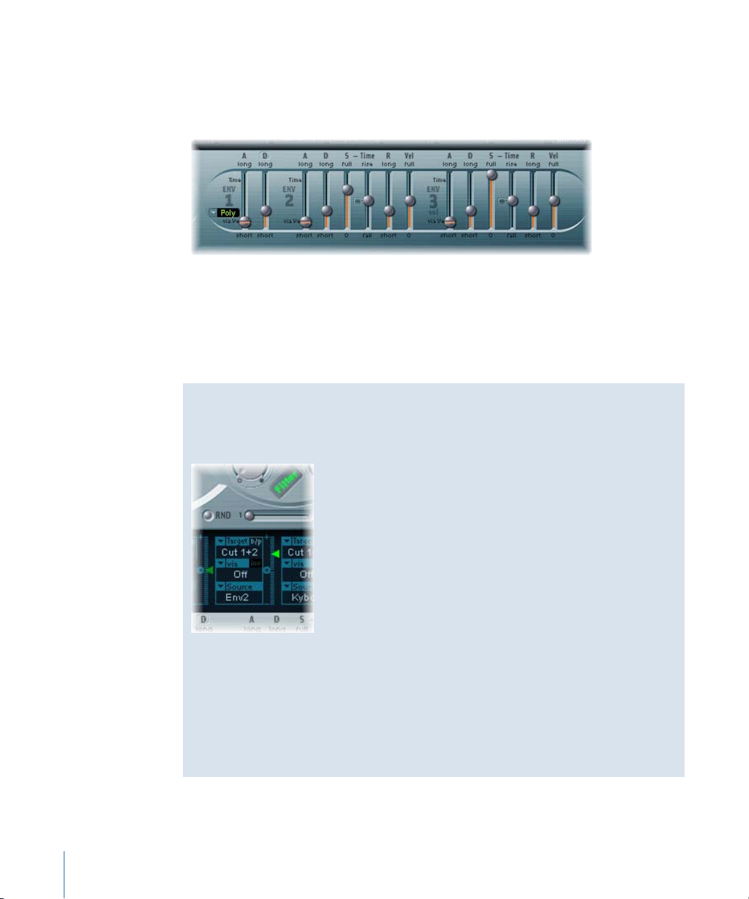
Getting to Know the ES2 Envelopes (ENV 1 to ENV 3)
The ES2 features three envelope generators per voice. They are abbreviated as ENV 1,
ENV 2, and ENV 3, respectively, in the interface and router. In addition, the ES2 features
the sophisticated Vector Envelope (see Getting to Know the ES2’s Vector Envelope).
Note: To learn more about the roots of the term “envelope generator” and its basic
functionality, see Synthesizer Basics.
The parameters of ENV 2 and ENV 3 are identical. ENV 3 defines the changes in level over
time for each note played. You can regard ENV 3 as being hard-wired to the router’s AMP
modulation target.
Envelope Modulation of ES2 Filter Cutoff
Unlike many other synthesizers, the ES2 has no hard-wired connection between any of
the envelope generators and the filter cutoff frequencies.
Set up a modulation routing as follows, in order to establish this type of modulation: Set
target to Cutoff 1, Cutoff 2, or Cut 1+2. Set source to ENV 2, for example. After it is set
as described, the slider to the right of the modulation routing will function as the filter’s
EG Depth parameter.
Note: Both ENV 2 and ENV 3 are velocity sensitive, making it unnecessary to set via to
Velo in the modulation routing; you can leave via off.
84 Chapter 5 ES2
Page 85

Getting to Know ENV 1 in the ES2
Decay/Release Mode
button
Trigger Modes menu
Attack via Velocity slider
Although ENV 1 might appear to be rather poorly equipped at first glance, its handful of
parameters are useful for a vast range of synthesizer functions.
• Trigger Modes menu: You can define the trigger behavior of ENV 1 by choosing one of
the following settings:
• Poly: The envelope generator behaves as you would expect on any polyphonic
synthesizer: Every voice has its own envelope.
• Mono: A single envelope generator modulates all voices in the same way. All notes
must be released before the envelope can be retriggered. If you play legato, or any
key remains depressed, the envelope won’t restart its attack phase.
• Retrig: A single envelope generator modulates all voices in the same way. The
envelope will be triggered by any key you strike, even when other notes are sustained.
All sustained notes are identically affected by the retriggered envelope.
• Attack via Velocity slider: The Attack time slider is divided into two halves. The lower
half defines the attack time when the keys are struck hard—at maximum velocity. The
upper half defines the attack time at minimum velocity. Drag the area between the
two slider halves to move them both simultaneously. If this area is too small to drag,
click an unused portion of the slider, and drag vertically.
• Decay/Release modebutton: Click to switch ENV 1between behaving as an Attack/Decay
and an Attack/Release envelope.
85Chapter 5 ES2
Page 86

Setting Envelope 1 Decay or Release in the ES2
Click here to switch
between Decay and
Release modes.
ENV 1 can be set to act as an envelope generator with either of the following: an Attack
time and Decay time parameter or an Attack time and Release time parameter.
To switch between Attack/Decay and Attack/Release modes
Click the D or the R above the right ENV 1 slider. The button label will change to reflect
µ
the mode that is activated.
• In Attack/Decay mode: The level will fall to zero after the attack phase has completed,
whether or not the note is sustained. It will decay at the same speed—even if you
release the key. The decay time is set with the D (Decay time) slider.
• In Attack/Release mode: The envelope level remains at its maximum after the attack
phase is over, while the key remains depressed. Following the release of the key, the
level decreases over the time period defined by the R (Release time) slider.
Emulating Classic Polysynth Filter Behavior in the ES2
Early analog polysynths passed all voices through a single lowpass filter. This design
decision was primarily due to cost factors. The best-known examples of these polyphonic
instruments were the Moog Polymoog, the Yamaha SK20, and the Korg Poly-800. The
sole lowpass filter of such instruments is controlled by a single envelope generator. To
simulate this behavior in the ES2, use the Mono or Retrigger modes.
Modulation of the Cutoff 2 target with a percussive source, such as ENV 1, which is set
to Retrig will have a percussive filter effect every time you play another key, if you play
and sustain a bass note. The newly struck key is also shaped by the same filter. Playing
a sound set up in this way feels like you’re playing a polyphonic synthesizer with one
filter. This is despite the fact that the ES2’s filters remain polyphonic and can be
simultaneously modulated by different polyphonic sources.
As a further tip, you can also simulate the percussion of a Hammond organ by using
the Mono or Retrigger modes.
Getting to Know ENV 2 and ENV 3 in the ES2
The feature sets of ENV 2 and ENV 3 are identical, but it is always the task of ENV 3 to
define the level of each note—to modulate the dynamic stage, in other words.
86 Chapter 5 ES2
Page 87

Attack Time slider is
divided into two halves
that determine the attack
time at maximum and
minimum velocities.
Click the center symbol
to set the Sustain Time
slider to its center value.
Sustain Time and Sustain
Level are set
independently in the ES2.
ENV 3 is, however, also available for simultaneous use as a source in the router. The
envelope time parameters can also be used as modulation targets in the router.
• Attack slider: Defines the length of time it takes for the level of a note to rise from an
amplitude of zero to the set amplitude. The Attack time sliders of ENV 2 and ENV 3 are
divided into two halves.
• The lower half defines the attack time when the keys are struck hard, at maximum
velocity. The upper half defines the attack time at minimum velocity. Drag the area
between the two slider halves to move them both simultaneously. If this area is too
small to be dragged, click in an unused portion of the slider and drag vertically.
• Decay slider: Determines the period it takes for the level of a held note to fall to the
sustain level, after the attack phase has completed.
• If the Sustain level parameter is set to its maximum value, the Decay parameter has
no effect.
• When the Sustain level is set to its minimum value, the Decay parameter defines the
duration or fade-out time of the note.
• Sustain and Sustain Time sliders: There are two sustain parameters that interact with
each other. One controls the sustain level, and the other controls the sustain time. See
Using the Envelope 2 and 3 Sustain Parameters in the ES2.
• (R) Release Time slider: Defines the time required for the (sustain) level to decay to
zero—after the key is released.
• Vel (Velocity Sensitivity) slider: Determines the velocity sensitivity of the entire envelope.
If set to maximum, the envelope will output its maximum level only when the keys are
struck at maximum velocity. Softer velocities result in a corresponding change to the
envelope levels—with a 50% velocity resulting in half-levels for each envelope-level
parameter.
87Chapter 5 ES2
Page 88

Using the Envelope 2 and 3 Sustain Parameters in the ES2
Vector Envelope
Solo Point
Curve Planar PadTriangle
Vector Mode
Loop RateLoop ModeEnv Mode Time Scaling Planar Pad
Targets
When the Sustain Time (rise) slider is set to its center value, the Sustain (S) Level slider
behaves like the sustain parameter of any synthesizer ADSR envelope.
In this position, the Sustain (Level) slider defines the level that is sustained while the key
remains depressed, following completion of the Attack time and Decay time phases.
The Sustain Time slider defines the time it takes for the level to rise from the Sustain level
back to its maximum level—or to fall to zero:
• Settings in the lower half of the Sustain Time slider range (fall) determine the time
required for the level to decay from the sustain level to zero. The lower the slider
position, the faster the sound level decays.
• Settings in the upper half of its range (rise) determine the time required for the level
to rise from the sustain level to its maximum value. The higher the slider position, the
faster the sound level rises.
Emulating Instrument Behaviors with Envelope Modulation
On pianos and plucked string instruments, high notes decay faster than low notes.
To simulate this effect, modulate the Decay Time target with the Kybd source in the
router. The modulation intensity slider should be set to a negative value.
Getting to Know the ES2’s Vector Envelope
The Vector Envelope is a multipoint, loop-capable control source. Its sole purpose is to
provide real-time control of square icon movements in the Triangle and the Planar Pad.
The Vector Envelope shares the space occupied by the modulation router, and it can be
viewed by clicking the Vector Envelope button to the right of the router.
88 Chapter 5 ES2
Page 89

Each voice is equipped with an independent Vector Envelope, which is triggered from
its start point with every new keystrike (MIDI note-on message).
Conceptually, the Vector Envelope—and Planar Pad and Triangle—may seem somewhat
strange, and perhaps a little intimidating, but a little experimentation on your part will
reveal how easy these features are to use. Combining these facilities with other ES2
synthesis options enables you to create some truly unique sounds that are—quite
literally—moving.
To activate or deactivate the Vector Envelope
Turn off the Solo Point button (described on Setting the ES2 Vector Envelope Solo Point)
µ
to activate the Vector Envelope.
Turn on the Solo Point button to deactivate the Vector Envelope.
µ
When Solo Point is turned on, only the currently selected Triangle and Planar Pad positions
of the currently selected point are active.
Vector Envelope Control of the ES2’s Planar Pad and Triangle
The Vector Mode pop-up menu below the Vector Envelope button allows you to specify
the target for the Vector Envelope—the Planar Pad and/or the Triangle.
• Off: The Vector Envelope does not control the Triangle or the Planar Pad. It is completely
turned off. This allows you to manually set and control the square icons of the Triangle
and the Planar Pad.
• Mix: The Vector Envelope controls the Triangle, but not the Planar Pad.
• XY: The Vector Envelope controls the Planar Pad, but not the Triangle.
• Mix+XY: The Vector Envelope controls both the Planar Pad and the Triangle.
89Chapter 5 ES2
Page 90

An Overview of ES2 Vector Envelope Points, Times, and Loops
Vector Envelope time axis
Point 1
Loop point is shown on
row below time axis.
Sustain point is shown
on row above time axis.
Point time value shown
in milliseconds (ms).
The Vector Envelope time axis runs from left to right.
Up to 16 points can be displayed on the time axis (10 are shown in the figure above).
Each point can control the square icon positions of the Triangle and the Planar Pad (as
described in Vector Envelope Control of the ES2’s Planar Pad and Triangle).
The points are numbered sequentially—from left to right—along the time axis.
µ
µ
90 Chapter 5 ES2
There are always at least three points: Point 1 is the start point, point 2 is defined as the
Sustain point, and point three is the end point.
Any point can be declared the Sustainpoint. If a played note is held for a sufficient length
of time and there’s no loop engaged, any envelope movement will stop when the Sustain
point is reached. The Sustain point value is maintained until the key is released—until
the MIDI note-off command.
Any point can be declared the Loop point. The looped area spans the time between the
Sustain point and Loop point. In between these points you can create further points that
describe the movements of the square icons in the Planar Pad and Triangle.
Selecting, Creating, and Deleting ES2 Vector Envelope Points
The more points you set, the more complex the movements that can be performed.
To select a point
Click to select. Once selected, you can freely edit the point.
To create a new point
Shift-click between two existing points.
Page 91

The segment that previously existed between the two old points is divided at the clicked
position. The sum of the two new segment times is equal to the time of the original
undivided segment. This ensures that following points retain their absolute time positions.
Existing square icon positions in the Triangle and Planar Pad are fixed, thus ensuring that
newly created points don’t affect any previously defined movements.
To delete a point
Control-click it.
µ
Reverting to Default ES2 Vector Envelope Point Values
On occasion you may want to revert to the default values of a point. This is done directly
in the Triangle or the Planar Pad:
To revert to the default value for a point, do one of the following
Option-click the Triangle. The square icon is set to the center position of the Triangle.
µ
All oscillators are set to output the same level.
Option-click the Planar Pad.
µ
The square icon is set to the center position of the Planar Pad. Both axis values are set to
zero.
Setting the ES2 Vector Envelope Solo Point
The Solo Point button basically turns off the Vector Envelope. If the Solo Point button is
activated, no dynamic modulations are generated by the Vector Envelope. In this scenario,
the currently visible square icon positions of the Triangle and Planar Pad are permanently
in effect. These square icon positions match the currently selected Vector Envelope point.
If you select another Vector Envelope point by clicking it, the square icon positions in the
Triangle and Planar Pad will update to reflect your selection. If the Solo Point button is
turned on, the newly selected point will become the Solo point.
Note: You can independently switch off Vector Envelope modulation of the Planar Pad
by setting Vector Mode to off, as described in Vector Envelope Control of the ES2’s Planar
Pad and Triangle.
Setting the ES2 Vector Envelope Sustain Point
As mentioned earlier, any point can be declared the Sustain point. Assuming that the
played note is held long enough and there’s no loop engaged, any envelope movement
will stop when this Sustain point is reached. The Sustain point value is maintained until
the key is released—until the MIDI note-off command.
To define a point as the Sustain point
Click in the turquoise strip above the desired point.
µ
91Chapter 5 ES2
Page 92

The Sustain point is indicated by an S between the point and its number shown on the
turquoise strip.
Setting Up ES2 Vector Envelope Loops
The Vector Envelope can run in one-shot mode—as long as the note is sustained; it can
be set to repeat a specific number of times; or it can repeat indefinitely—much like an
LFO modulation. You can achieve repetitions by using the loop functions.
Although the loop parameters may remind you of the loop parameters available for
samples, there are significant differences between them. The Vector Envelope only supplies
control signals that are used to move the square icon positions of the Triangle and Planar
Pad. The audio output of the ES2 is not looped in any way.
Setting the Loop Point
Any point can be declared the Loop point. Provided that the note is held for a suitable
length of time, portions of the envelope can be repeated, or looped.
The looped area spans the time between the Sustain point and theLoop point. In-between
these points you can define several points that describe square icon movements in the
Triangle and the Planar Pad.
To define a point as the Loop point
Click in the turquoise strip below the desired point.
µ
A Loop point is indicated by an L in the strip below.
Note: To see and define the Loop point, Loop Mode must be activated (see “Setting the
Vector Envelope Loop Mode” below).
92 Chapter 5 ES2
Page 93

Setting the ES2 Vector Envelope Loop Mode
Click here to choose a
Loop mode.
You can choose from the following Vector Envelope Loop modes: Off, Forward, Backward,
and Alternate.
• Off: When Loop Mode is set to Off, the Vector Envelope runs in one-shot mode from
beginning to end—if the note is held long enough to complete all envelope phases.
The other loop parameters are disabled.
• Forward: When Loop Mode is set to Forward, the Vector Envelope runs from the
beginning to the Sustain point—then begins to periodically repeat the section between
the Sustain point and the Loop point—in a forward direction.
• Backward: When Loop Mode is set to Backward, the Vector Envelope runs from the
beginning to the Sustain point—then begins to periodically repeat the section between
the Sustain point and the Loop point—in a backward direction.
• Alternate: When Loop Mode is set to Alternate, the Vector Envelope runs from the
beginning to the Sustain point—then periodically switches to the Loop point, then
back to the Sustain point—alternating between backward and forward directions.
Setting the ES2 Vector Envelope Loop Rate
Just as every LFO has a speed, or rate, parameter, the loop can be set to cycle at a defined
speed. The Vector Envelope Loop Rate can also be synchronized with the project tempo.
To adjust the Vector Envelope loop rate, do one of the following
Drag the green indicator in the center of the Loop Rate bar to the left or right.
µ
Drag vertically in the value field “as set” (shown in the figure below).
µ
• As set: If you switch the Loop Rate to “as set,” the loop cycle length will equal the sum
of the times between the sustain and Loop points. Click the field labeled “as set” below
the Rate slider to select it.
• Rhythmic: If you set the Loop Rate to one of the rhythmic values (sync) by dragging
the Loop Rate indicator towards the left half of the slider, the loop rate will follow the
project tempo. You can choose from 32 bars up to a 64th triplet note value.
93Chapter 5 ES2
Page 94

• Free: You can also set a free Loop Rate by dragging the Loop Rate indicator towards
the right half of the slider (free). The value indicates the number of cycles per second.
Note: If Loop Rate is not switched to “as set,” and Loop Mode (Forward, Backward, or
Alternate) is active, the times of points between the Loop and Sustain points and the
Loop Smooth value are shown as a percentage of the loop duration, rather than in
milliseconds.
Making Smooth ES2 Vector Envelope Loop Transitions
When Loop Mode is set to Forward or Backward, there will inevitably be a moment when
a transition from the Sustain point to the Loop point occurs. You can use the Loop Smooth
parameter to even out the transition, thus avoiding abrupt position changes.
• If the Loop Rate parameter is set to Sync or Free, the loop smoothing time is displayed
as a percentage of the loop cycle duration.
• If the Loop Rate parameter is “as set,” the loop smoothing time is displayed in
milliseconds (ms).
Specifying an ES2 Vector Envelope Loop Count
The loop cycle of the Vector Envelope can be repeated a specified number of times. After
the defined number of repetitions have occurred, the Vector Envelope will run from the
Sustain point onwards. Possible values are 1 to 10 and “infinite.”
Setting the ES2 Vector Envelope Release Phase Behavior
There are two release phase options in the Env Mode menu: Normal and Finish.
Using the Normal ES2 Vector Envelope Mode
If the Env Mode menu is set to Normal, the release phase—the phase after the Sustain
point—begins as soon as you release the key (note off). In other words, the release phase
will start from the Vector Envelope point where you released the key.
The following behaviors apply:
• If looping is turned off and the Vector Envelope reaches the Sustain point, the Sustain
point value will be retained for as long as you hold a key.
• If looping is turned on and the Loop point is positioned before the Sustain point, the
loop will cycle for as long as you hold a key.
• If looping is turned on and the Loop point is positioned after the Sustain point, the
Vector Envelope loop will continue to cycle until the overall release phase of the sound,
as determined by the ENV 3 Release parameter, has completed.
94 Chapter 5 ES2
Page 95

Using the Finish ES2 Vector Envelope Mode
If the Env Mode menu is set to Finish, the Vector Envelope does not immediately
commence the release phase when you release the key. Rather, it plays all points for their
full duration until the end point is reached, regardless of whether you hold the key or
release it.
The following behaviors apply:
• If looping is turned off, the Sustain point is ignored. The Vector Envelope will complete
all points up to the end point, regardless of whether you hold the key or release it.
• If looping is turned on, the Vector Envelope will play all points until it reaches the Loop
point, and then play the loop until the end point is reached. It does not matter if the
Loop point is positioned before or after the Sustain point.
• If looping is turned on, and Loop Count is set to a value other than “infinite,” the Vector
Envelope will continue on to the subsequent points—following completion of the
specified number of loop repetitions. If Loop Count is set to “infinite,” the points after
the loop are irrelevant. See ES2.
Choosing ES2 Vector Envelope Point Transition Shapes
The Curve parameter defines the shape of the transition from point to point. You can
choose from nine convex and nine concave shapes. There are also two unusual curve
forms, “hold+step” and “step+hold,” which allow stepped modulations.
• step+hold: This curve jumps at the beginning of the transition.
• hold+step: This curve jumps at the end of the transition.
Note: You can use “hold+step” to create stepped vector grooves—with up to 15 steps.
Setting ES2 Vector Envelope Times
With the exception of the first point, which is tied to the beginning of each played note,
every point has a Time parameter. This parameter defines the period of time required for
the position indicator to travel from the point that preceded it. The times are normally
displayed in milliseconds (ms).
To adjust a time value
Click the numerical value and drag vertically.
µ
Note: Changing a time value alters the absolute time positions of all subsequent points.
95Chapter 5 ES2
Page 96

To adjust a time value without affecting the absolute time positions of later points
Click here to change the
time scale.
Control-drag the Time parameter to increase or decrease the time required to reach the
µ
following point. The time setting of the ensuing point is simultaneously adjusted—by a
corresponding amount. This ensures that the adjacent and all following points retain
their absolute time positions.
Time Scaling the ES2’s Vector Envelope
You can stretch and compress the entire Vector Envelope. This is extremely useful if you
want to double the Vector Envelope’s speed, for example. Rather than halving the time
values of every point, you can set the Time Scaling parameter above the ENV3 Attack
slider to 50%.
• The Time Scaling parameter ranges from 10% to 1000%. It is scaled logarithmically.
• If the Loop Rate is “as set,” scaling also affects the loop.
• If the Loop Rate is set to a free or synced value, the setting is not affected by the Time
Scaling parameter.
ES2 Fix Timing—Normalizing Time Scaling and the Loop Rate
Clicking the Fix Timing button (to the right of the Time Scaling parameter) multiplies the
Time Scaling value by all time parameters, and Time Scaling will be reset to 100%. There
will be no audible difference. This is simply a normalizing procedure, similar to the
Normalizing function in the Region parameter box.
In cases where Loop Rate is set to a synced value, clicking Fix Timing will switch the Loop
Rate to “as set,” thus preserving the absolute rate.
96 Chapter 5 ES2
Page 97

Using the ES2 Vector Envelope Shortcut Menu
Vector Mode menu
Vector Intensity parameters
Vector Target menus
Planar Pad
A number of Vector Envelope commands and functions can be accessed by right-clicking
anywhere in the Vector Envelope. This will launch the pop-up menu shown below.
Choose any item in the menu to perform the command or function.
Using the ES2’s Planar Pad
The Planar Pad has two axes—X and Y. The X axis is on the horizontal plane and the Y
axis is on the vertical plane.
You can modulate one user-defined parameter with the X value and another user-defined
parameter with the Y value, allowing you to use the mouse like a joystick.
The X and Y axes have positive and negative value ranges. When you drag the square
icon, the values of both axes are continuously transmitted.
97Chapter 5 ES2
Page 98

Choosing a Vector Target—Modulation Destinations
The Vector X and Vector Y Target menus determine which parameter is modulated by
square icon movements in the Planar Pad. The modulation targets are identical to those
in the router. See ES2 Modulation Target Reference for descriptions.
The position of the square icon in the Planar Pad is also available in the router, as the
Pad-X and Pad-Y source and via options. See ES2 Modulation Source Reference and Using
Via Sources to Control ES2 Modulation Intensity.
Setting the Vector Intensity—Defining the Modulation Intensity
The maximum intensity, sensitivity, and polarity of the modulation is set with the Vector
X Int and Vector Y Int parameters.
To adjust the modulation intensity
Drag vertically in the Vector X and Y Int fields.
µ
Use a negative value to invert the modulation polarity.
ES2 Modulation Target Reference
The following targets are available for real-time modulation.
ES2 Oscillator Targets
The table below includes all oscillator-related modulation targets.
CommentsTarget
Pitch123
Pitch 1
Modulates the frequencies (pitch) ofall three oscillators. If you select
an LFO as the source, this target leads to siren or vibrato sounds.
Select one of the envelope generators with zero attack, short decay,
zero sustain, and short release as the source for tom and kick drum
sounds.
Modulates the frequency (pitch) of Oscillator 1. Slight envelope
modulations can make the amount of detuning change over time,
when Oscillator 1 is sounding in unison with another (unmodulated)
oscillator. This also applies to the other Pitch targets and is
particularly useful for synthesizer brass sounds.
Modulates the frequency (pitch) of Oscillator 2.Pitch 2
Modulates the frequency (pitch) of Oscillator 3.Pitch 3
98 Chapter 5 ES2
Page 99

Detune
CommentsTarget
Controls the amount of detuning between all three oscillators. The
sensitivity of all pitch modulation targets is determined by the
modulation intensity. This is scaled as per the lists below, allowing
you to create very delicate vibrati in the cent range (1/100 semitone),
and huge pitch jumps by octaves.
• Modulation intensity from 0 to 8: steps are 1.25 cents.
• Modulation intensity from 8 to 20: steps are 3.33 cents.
• Modulation intensity from 20 to 28: steps are 6.25 cents.
• Modulation intensity from 28 to 36: steps are 12.5 cents.
• Modulation intensity from 36 to 76: steps are 25 cents.
• Modulation intensity from 76 to 100: steps are 100 cents.
This leads to the following rules of thumb for modulation intensity
values.
• Intensity of 8 equals a pitch shift of 10 cents.
• Intensity of 20 equals a pitch shift of 50 cents (one quarter tone).
• Intensity of 28 equals a pitch shift of 100 cents (one semitone).
• Intensity of 36 equals a pitch shift of 200 cents (two semitones).
• Intensity of 76 equals a pitch shift of 1,200 cents (one octave).
• Intensity of 100 equals a pitch shift of 3,600 cents (threeoctaves).
OscWaves
Osc1Wave
Osc2Wave
Osc3Wave
Depending on the waveforms set in the three oscillators, this target
can be used to modulate:
• The pulse width of rectangular and pulse waves
• The amount of frequency modulation (Oscillator 1 only)
• Noise color (Oscillator 3 only)
• The position of the Digiwaves
OscWaves affects all oscillators simultaneously.
For further information about the effects of these modulations, see
Using Pulse Width Modulation in the ES2, Using Frequency
Modulation in the ES2, Using Noise in the ES2 (Oscillator 3 Only),
and Using Digiwaves in the ES2.
Depending on the waveform selected for Oscillator 1, you can control
the pulse width of rectangular and pulse waves, the amount of
frequency modulation, or the position of the Digiwave. Note: In
classic FM synthesizers the amount of FM is controlled in real time
by velocity-sensitive envelope generators. Select one of the ENVs
as the source for such sounds.
The same as Osc1Wave, except that Oscillator 2 does not feature
FM. Note that pulse width modulation also works with both the
synchronized rectangular and ring modulated rectangular waves.
Oscillator 3 is the same as Osc1Wave and Osc2Wave except that it
does not feature FM or ring modulation. Oscillator 3 features noise,
the color of which can be modulated with this parameter.
99Chapter 5 ES2
Page 100

OscWaveB
Osc1WaveB
SineLev1
OscLScle
CommentsTarget
The transitions between Digiwaves during a wavetable modulation
(where youswitch between different Digiwaves) are always smooth.
You can use the OscWaveB target to continuously modulate the
shape of the transitions from smooth to hard. This target applies
to all oscillators.
If wavetable modulation is active for a Digiwave (using the Osc1Wav
target), you can use this target to modulate the shape of the
transition. When you are frequency-modulating Oscillator 1, the
Osc1WaveB target offers much higher FM intensities than either
the Osc1 FM or the Osc1Wave targets.
The same as above for a Digiwave using the Osc2Wav target.Osc2WaveB
The same as above for a Digiwave using the Osc3Wav target.Osc3WaveB
SineLevl (Sine Level) allows the sine wave level of Oscillator 1 to be
modulated. The parameter defines the level of the first partial tone
of Oscillator 1. See Thickening the ES2’s Sound with Sine Level.
OscLScle (Osc Level Scale) modulates the levels of allthree oscillators
simultaneously. A modulation value of 0 mutes all oscillators,
whereas a value of 1 raises the gain of the entire mix by 12 dB. The
modulation is applied before the overdrive stage, allowing for
dynamic distortions.
(Osc 1 Level) allows modulation of Oscillator 1’s level.Osc1Levl
(Osc 2 Level) allows modulation of Oscillator 2’s level.Osc2Levl
(Osc 3 Level) allows modulation of Oscillator 3’s level.Osc3Levl
ES2 Filter Targets
The table below includes all filter-related modulation targets.
Cutoff 1
LPF FM
Cut 1+2
100 Chapter 5 ES2
CommentsTarget
Modulates the Cutoff Frequency parameter of Filter 1. See Using
the ES2 Filter Cutoff and Resonance Parameters.
(Reso 1) Modulates the Resonance parameter of Filter 1.Resonance 1
Modulates the Cutoff Frequency parameter of Filter 2.Cutoff 2
(Reso 2) Modulates the Resonance parameter of Filter 2.Resonance 2
Determines the intensity of the lowpass filter frequency modulation
(LPF FM) of Filter 2—with a sine wave (at the same frequency as
Oscillator 1). This parameter is described in Modulating Filter 2’s
Frequency in the ES2.
Modulates the cutoff frequency of both filters in parallel. This is like
applying the same modulation to Cutoff 1 and Cutoff 2 in two
modulation routings.
 Loading...