

Page 1
K
Service Source
Color StyleWriter
4100 and 4500
Page 2
K
Service Source
Basics
Color StyleWriter 4000 Series
Page 3
Basics Overview - 1
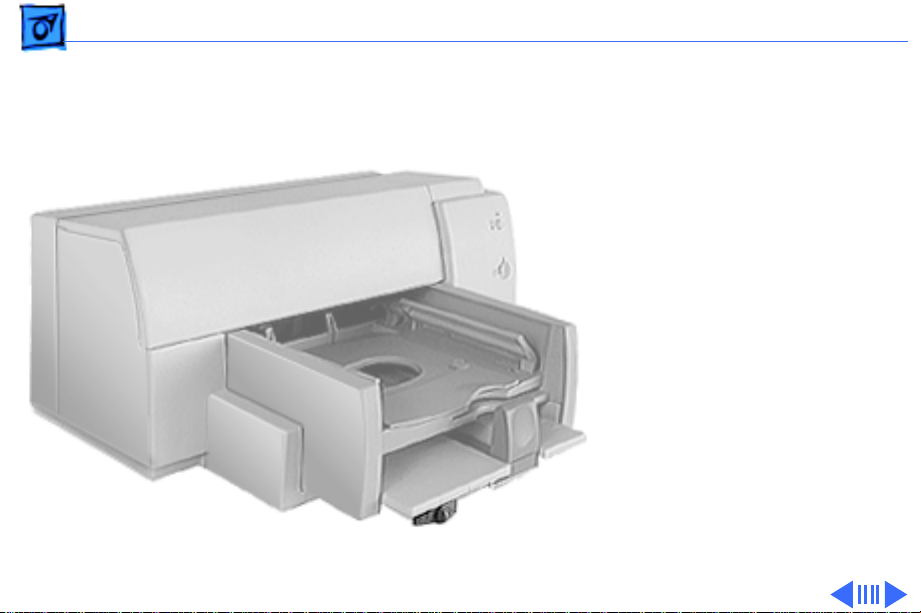
Overview
The Color StyleWriter 4000
Series printers are desktop
color bubble-jet printers
for personal use.
Page 4

Basics Overview - 2
Color StyleWriter 4500 and 4100 Differences
The Color StyleWriter 4500 and the Color StyleWriter
4100 differ in the following ways:
• Color StyleWriter 4500 can produce photo-quality
prints.
• Color StyleWriter 4500 can print on banner (zfold) paper.
• Color StyleWriter 4500 prints slightly faster than
the Color StyleWriter 4100.
Page 5

Basics Overview - 3
Ink Cartridge Configurations
The Color StyleWriter 4500 and 4100 can be configured
with
• Color ink cartridge
• High-performance black ink cartridge
The Color StyleWriter 4500 can also be configured with
• Color ink cartridge
• PhotoGrade ink cartridge.
In the Color StyleWriter 4500, replace the black cartridge
with the PhotoGrade ink cartridge for photo-quality
printing.
Page 6
Basics Overview - 4
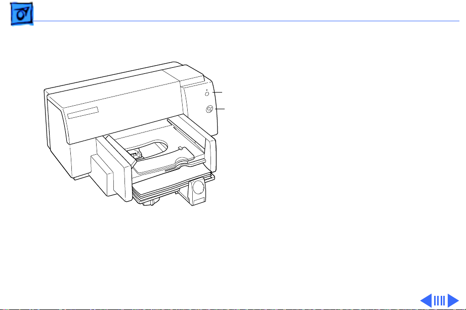
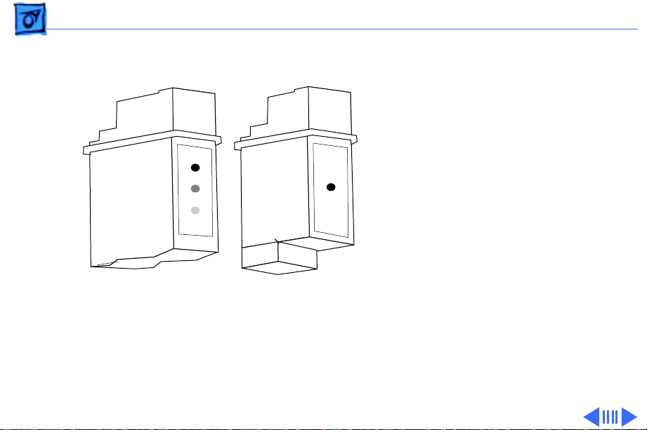
Troubleshooting LEDs
The Color StyleWriter 4500
and 4100 have two LEDs,
Resume
Power
Power and Resume, that can
aid in troubleshooting the
printer. See the
Troubleshooting chapter for
more information.
Page 7

Basics Overview - 5
Ink-jet Technology
Overview
Thermal ink-jet technology involves applying heat to a tiny
measure of ink until it expands and forms a bubble. As the
bubble continues to expand and burst, it is propelled
through one of the nozzles on the ink cartridge. This process
is repeated up to 8,000 times per second.
Each ink cartridge on the Color StyleWriter 4500 and 4100
has 48 nozzles. On the black ink cartridge, all 48 nozzles
are used for black ink. On the color and PhotoGrade
cartridges each color (cyan, magenta, and yellow) has 16
nozzles each.
Page 8

Basics Overview - 6
Photo Printing Technology
The Color StyleWriter 4500 uses multiple dye-load
technology to produce photorealistic print-outs. Two ink
cartridges are used to produce these results: the color and
the photo ink cartridges. The color cartridge contains cyan,
magenta, and yellow inks. The PhotoGrade cartridge contains
cyan, magenta, and yellow inks mixed with a black pigment.
The three additional colors in the PhotoGrade cartridge
quadruples the number of ink color ratios that can be
printed in a given area. The resulting colors produced from
the PhotoGrade cartridge are more subtle shades and hues.
The PhotoGrade cartridge also produces smaller ink
droplets, which can be layered on top of each other to vary
the intensity.
Page 9
Basics Ink Cartridge Identification - 7
Ink Cartridge Identification
Color Cartridge
Black Cartridge
Caution:
printer’s ink on your hands
or clothes. Although the ink
is water soluble, it contains
dyes that will stain.
Note:
StyleWriter 4500 includes
three ink cartridges: black,
color, and PhotoGrade.
The Color StyleWriter 4100
includes only the black and
color cartridges.
Do not get the
The Color
Page 10

Basics Ink Cartridge Identification - 8
High-Performance, Black-Only Ink Cartridge
The black ink cartridge contains black ink only.
Color Ink Cartridge
The color ink cartridge contains cyan, magenta, and yellow
inks.
Color PhotoGrade Ink Cartridge
The PhotoGrade ink cartridge contains cyan, magenta, yellow
inks and black pigment.
Important:
cartridge and PhotoGrade paper. For photorealistic results,
the kit contents must be used together. These parts cannot be
used in the Color StyleWriter 4100.
The Color StyleWriter 4500 includes the ink
Page 11
Basics Ink Cartridge Identification - 9
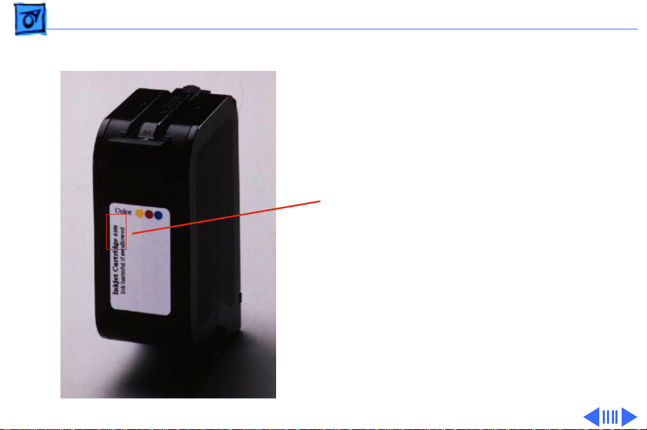
Identifying Replacement Ink Cartridges
The ink cartridges used
with the Color StyleWriter
4100 and 4500 have a
6105
generic cartridge labels.
There is no Apple logo or
Apple part number on the
cartridge. To identify a
cartridge, refer to the
small numeric part number
on the label. This number
can be cross-referenced to
the appropriate Apple
Marketing number in the
chart that follows.
Page 12
Basics Ink Cartridge Identification - 10
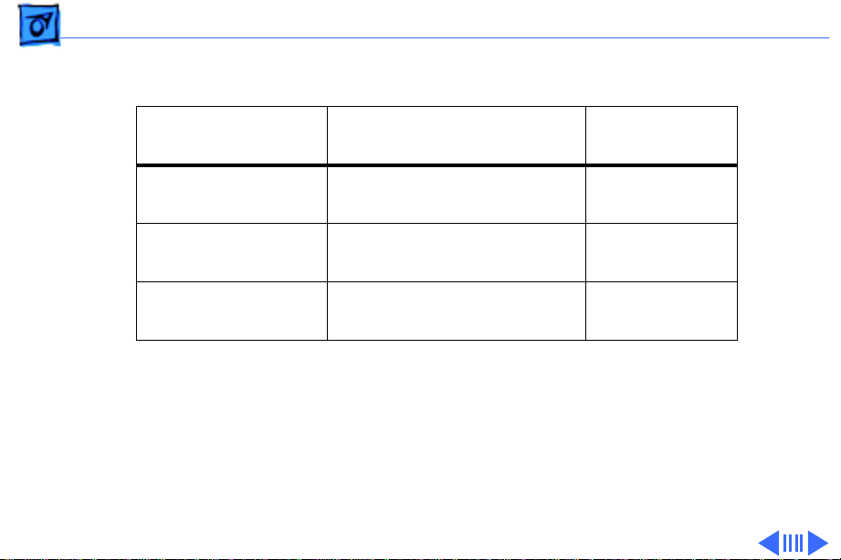
Identify ink cartridges by cross referencing the chart below.
Apple Marketing
Part Number
Product Description HP Cartridge
M5694G/A Color Ink Cartridge (CSW
4100 & 4500)
M5693G/A Black Ink Cartridge (CSW
4100 & 4500)
M5692G/A Color PhotoGrade Ink
Cartidge (4500 only)
Note
: Apple ink cartridges can be found at most Apple authorized dealers, as well as
most office product and computer superstores. Catalog and mail order houses which
specialize in Macintosh products, such as MacWarehouse, MacMall, and MacZone carry
a complete selection of genuine Apple Printer Supplies. You can also call the Apple
Reseller Referral number at 1-800-538-9696, which will refer you to an
authorized Apple dealer in your area.
6107
6106
6104
Page 13

Basics Recommended Paper - 11
Recommended Paper
Apple recommends Apple
Color Ink-Jet PREMIUM
PLUS Coated Paper. It is the
coated paper of choice to use
with the Color StyleWriter
4100 and 4500 ink-jet
printer.
• Letter size p/n M4792G/
A
• A4-size p/n M4791G/A.
Page 14

Basics Printing a Photograph - 12
Printing a Photograph
The Color StyleWriter 4500 has the capability to produce
photo-quality printouts. Follow these procedures
1 Remove the black print cartridge and replace it with the
PhotoGrade Ink cartridge.
2 Load the PhotoGrade paper into the sheet feeder so the
whiter side faces you.
Page 15
Basics Printing a Photograph - 13
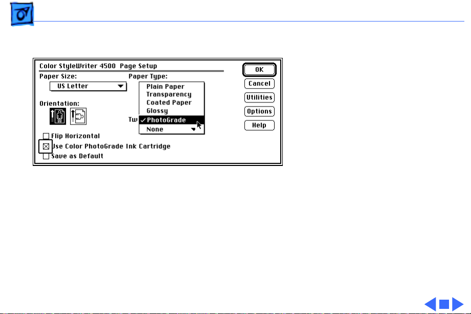
3 Choose Page Setup from
the File menu.
4 In the Page Setup dialog
box, select PhotoGrade
from the Paper Type
pop-up menu.
5 Select the “Use Color
PhotoGrade Ink
Cartridge” option.
6 Click Print.
Page 16
Basics Printing a Banner - 14
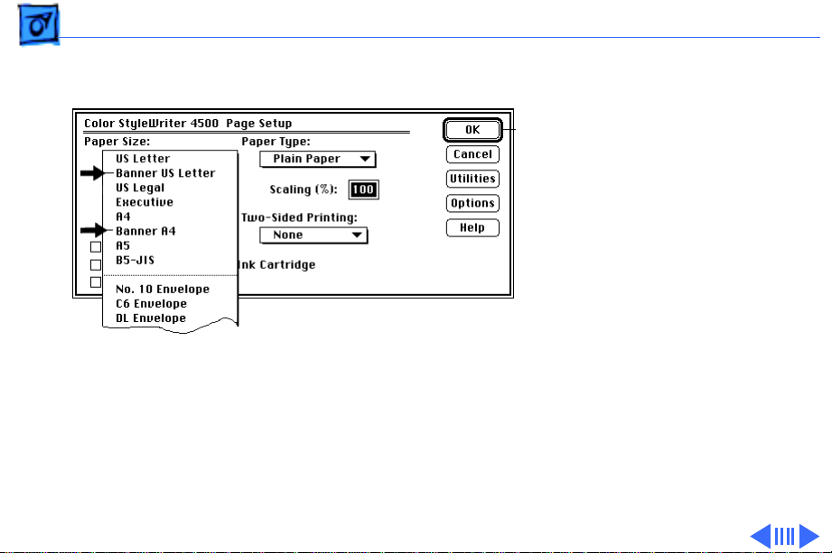
Printing a Banner
Follow these steps to print
on banner (z-fold) paper
using the Color StyleWriter
4500.
1 Choose Page Setup from
the File menu.
2 In the Page Setup dialog
box, choose either
Banner US Letter or
Banner A4 from the
Paper Size pop-up
menu.
Page 17
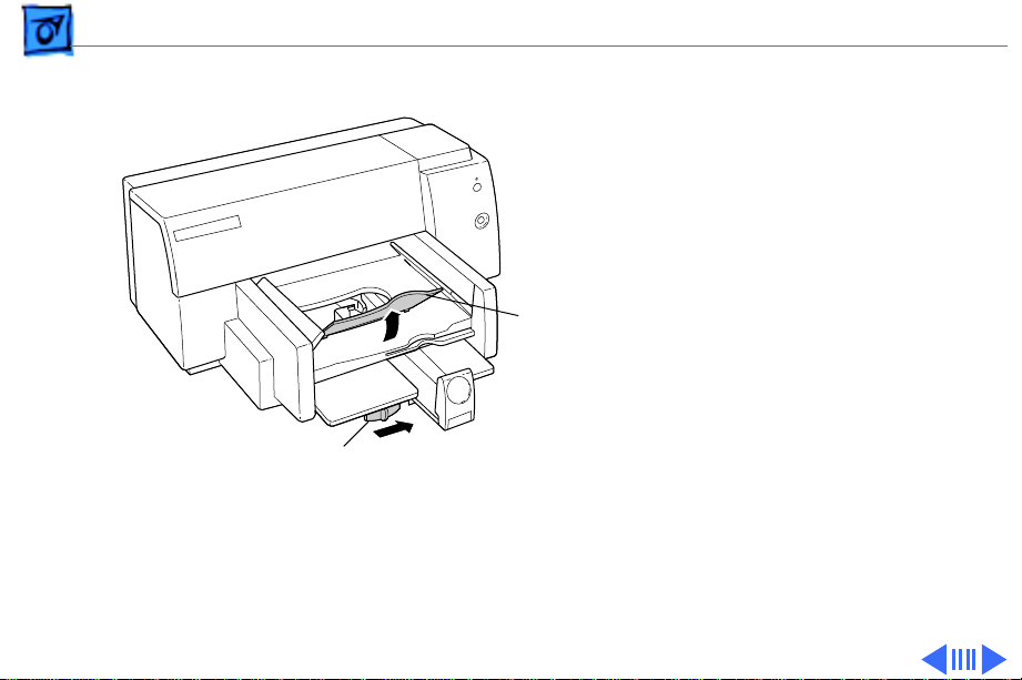
Basics Printing a Banner - 15
3 Slide the banner lever
to the right until it
clicks into place.
4 Remove all paper from
the input tray.
5 Flip up the banner
Banner
Support
support in the output
tray.
6 Put the paper in the
input tray, with a torn
Banner Lever
edge at the top of the
stack, facing lengthwise
into the printer.
Page 18

Basics Printing a Banner - 16
7 Slide the paper width and
length adjusters so they
touch the edges of the
stack of paper.
8 Click Print.
Note:
When printing
stops, press the Resume
button as many times as
necessary to advance the
remaining banner paper
out of the printer.
Page 19

Basics Special Servicing Considerations - 17
Special Servicing Considerations
Banner Calibration
After replacing the logic board or ink cartridges you must
re-calibrate the Color StyleWriter 4500 banner printing.
Performing this calibration requires using the Color
StyleWriter 4500 Banner Calibration utility found in the
Diagnostic folder on the Companion CD. Refer to Additional
Procedures for more information.
Capping Assembly Replacement
If a Color StyleWriter 4100 or 4500 printer is brought in
for service, and the customer has had the printer for
awhile, replace the capping unit.
Capping Assembly 4100: 922-3010
Capping Assembly 4500: 922-2855
Page 20

Basics - 18
Mechanical Assembly Screws
Important:
screws (for any reason) that are not called out in the Take
Apart chapter for the Color StyleWriter 4000 Series.
Doing so will put the printer out of alignment and will
require installing a new mechanical assembly.
Do not touch/remove mechancial assembly
Page 21
K
Service Source
Specifications
Color StyleWriter 4000 Series
Page 22

Specifications Characteristics - 1
Characteristics
Print Methods
Throughput
Serial bubble jet ink-on-demand
Best
:
Up to one page per minute with the black ink cartridge
Up to .3 page per minute for color
Normal
Up to three pages per minute with the black ink cartridge
Up to .8 page per minute for color
Draft
Up to five pages per minute with the black ink cartridge
Up to 1.7 pages per minute for color
Actual speed depends on the documents printed and the Macintosh
:
:
used.
Page 23

Specifications Characteristics - 2
Note:
The Color StyleWriter 4100 prints at slightly slower
rates: up to four pages per minute with the black ink cartridge,
and up to 1.4 pages per minute for color.
Interfaces
• High-speed serial RS-422 port supports serial connection
• Printer can be hooked up to LocalTalk, but not as a shared
printer.
Page 24

Specifications Graphics - 3
Graphics
Resolution
Black:
Best: 600 x 600 dpi
Normal: 600 x 300 dpi
Draft: 300 x 300 dpi
Color & Black:
All Modes (plain paper): 300 x 300 dpi
All Modes (other media paper): 600 x 300 dpi
Color & Photo
Best & Normal (photograde paper): 600 x 300 dpi
Note:
photo ink cartridge.
:
The Color StyleWriter 4100 cannot print using the
Page 25

Specifications Print Media - 4
Print Media
Cut Sheets
Labels
Plain paper, coated (recommended for color picture output)
Color PhotoGrade paper (required for photorealistic color output)
LTR, LGL, Executive, A4, A5, B5
U.S. Letter (LTR): 8.5 x 11 in. (215.9 mm x 279.4 mm)
U.S. Legal (LGL): 8.5 x 14 in. (215.9 mm x 355.6 mm)
U.S. Executive: 7.25 x 10.5 in. (184.1 x 266.7 mm)
A4: 8.3 x 11.7 in. (210 mm x 297 mm)
A5: 5.8 x 8.3 in. (148.5 x 210 mm)
B5: 7.2 x 10.1 in. (182 x 257 mm)
Weight: 16-36 lb. Capacity: 100 sheets
Avery paper labels designed for inkjet printers
Letter, A4
Capacity: 25 sheets.
Page 26

Specifications Print Media - 5
Banner
Cards
Transparencies
U.S. Letter Banner: 8.5 x 11 in. (216 x 279 mm)
U.S. A4 Banner: 8.5 x 14 in. (216 x 356 mm)
Weight: 20 lbs. Capacity: 20 sheets
Note:
The Color StyleWriter 4100 cannot print on banner
paper.
U.S. 4 x 6: 4 x 6 in. (101.6 x 152.4 mm)
U.S. 5 x 8: 5 x 8 in. (127 x 203.3 mm)
A6: 4.1 x 6 in. (105 x 148.5 mm)
Height: 3.9 x 5.8 in. (100 x 148 mm)
Weight: 29-53 lbs. Capacity: 30 cards
Coated transparencies, most inkjet transparencies
Capacity: 50 sheets
Page 27

Specifications Print Media - 6
Envelopes
#10: 9.5 x 4.12 in. (241.3 x 104.4 mm)
DL: 4.33 x 8.66 in. (110 x 220 mm)
C6: 4.49 x 6.38 in. (114 x 162 mm)
A2: 4.375 x 5.75 in. (111 x 146 mm)
Weight: 20-24 lbs. Capacity: 20 envelopes
Page 28
Specifications Printable Area - 7
Printable Area
Paper, Labels, & Transparencies
U.S. Letter
U.S. Legal
U.S. Executive
A4
: 8.3 x 11.7 in. (210 mm x 297 mm)
Top margin:.26 in. (6.6 mm)
Bottom margin:.59 in. (14.9 mm)
Left & right margins: .25 in. (6.4 mm)
A5
: 5.8 x 8.3 in. (148.5 x 210 mm)
Top margin: 26 in. (6.6 mm)
Bottom margin: .84 in. (21.3 mm)
Left & right margins: .25 in. (6.4 mm)
B5
: 7.2 x 10.1 in. (182 x 257 mm)
Top margin: 26 in. (6.6 mm)
Bottom margin: .59 in. (14.9 mm)
Left & right margins: .25 in. (6.4 mm)
: 8.5 x 11 in. (215.9 mm x 279.4 mm)
: 8.5 x 14 in. (215.9 mm x 355.6 mm)
: 7.25 x 10.5 in. (184.1 x 266.7 mm)
Page 29

Specifications Printable Area - 8
Envelopes
Cards
#10
: 9.5 x 4.12 in. (241.3 x 104.4 mm)
DL
: 4.33 x 8.66 in. (110 x 220 mm)
C6
: 4.49 x 6.38 in. (114 x 162 mm)
A2
: 4.375 x 5.75 in. (111 x 146 mm)
Top margin: .84 in. (26 mm)
Bottom margin: .29 in. (6.6 mm)
Left & right margins: 0.125 in. (3.2 mm)
U.S. 4 x 6
U.S. 5 x 8
A6
: 4.13 x 6 in. (105 x 148.5 mm)
Height
Top margin: 0.26 in. (6.6 mm)
Bottom margin: 21.3 in. (.84 mm)
Left & right margins: 0.25 in. (6.4 mm)
: 4 x 6 in. (101.6 x 152.4 mm)
: 5 x 8 in. (127 x 203.3 mm)
: 3.9 x 5.8 in. (100 x 148 mm)
Page 30

Specifications Ink Cartridges - 9
Ink Cartridges
Type
Ink Color
Shelf Life
Black ink cartridge with integrated ink tank and print head
Three-color ink cartridge with three ink tanks (cyan, magenta,
yellow) and integrated print head
Color PhotoGrade ink cartridge with three ink tanks and integrated
print head
Black
Color (Cyan, magenta, yellow)
PhotoGrade (Cyan, magenta and yellow dyes, and Black pigment)
6 months (installed in printer)
18 months (in original package)
Page 31

Specifications Ink Cartridges - 10
Print Cartridge Life
Typical Usable Ink
Number of Nozzles
Black ink cartridge
650 pages at 5% coverage
Color ink cartridge
350 pages at 15% coverage
PhotoGrade ink cartridge
250 pages at 15% coverage
Black ink cartridge
40 ml
Color & PhotoGrade ink cartridges
7.6 ml per tank
Black ink cartridge
48 nozzles
Color and PhotoGrade ink cartridges
48 nozzles (16 per color)
Page 32

Specifications Environmental - 11
Environmental
Acoustic Noise Level
Temperature
Humidity
Best: 48 dB
Normal: 50 dB
Draft: 52 dB
Operating: 41–104°F (5-40°C)
Storage: -40-140°F (-40-60°C)
10–80% (noncondensing)
Page 33

Specifications Electrical - 12
Electrical
Electrical Requirements
Power Consumption
AC power adapter
U.S./Japan: 102-132 VAC, 60 Hz ± 3%
UK/Australia: 204-264 VAC, 50 Hz
Europe: 196-253 VAC, 50 Hz
Powered Off (plugged in): 2 W
Powered On (non-printing): 4.5 W
Powered On (printing): 12 W
Page 34

Specifications Physical - 13
Physical
Dimensions
Weight
Height: 7.9 in. (199 mm)
Width: 17.2 in. (436 mm)
Depth: 16 in. (405 mm)
11.6 lb (5.3 kg)
Page 35

K
Service Source
Take Apart
Color StyleWriter 4000 Series
Page 36

Take Apart Output Tray - 1
Output Tray
Output Tray
Output Tray
1 Slide the output tray out
and remove it from the
printer.
Page 37

Take Apart Access Door - 2
Access Door
Access Door
No preliminary steps are
required before you begin
this procedure.
Note:
Removing the access
door is not required, but it
may allow you to remove the
top cover more easily.
Page 38

Take Apart Access Door - 3
1 Pull the access door off
Hinge
Hinge
Access Door
of the two hinges on the
top cover.
Page 39

Take Apart Banner Lever - 4
Banner Lever
Before you begin, remove
the output tray.
Note:
The Color StyleWriter
4100 does not include the
Banner Lever.
Banner Lever
Page 40

Take Apart Banner Lever - 5
1 Rest the printer on its
side with the bottom
facing you.
2 Move the banner level to
the right.
Hole
3 Insert a small flatblade
screwdriver into the
access hole of the
printer’s base.
4 Push and release the
latch.
5 Pull the banner lever off
of the base.
Banner Lever
Page 41

Take Apart Length Adjuster - 6
Length Adjuster
No preliminary steps are
required before you begin
this procedure.
Length Adjuster
Page 42

Take Apart Length Adjuster - 7
Length Adjuster
Latch
Opening #2
Latch
Opening #1
1 Rest the printer on its
side.
2 Pull the length adjuster
straight out until it
stops.
3 Press and release latch
at opening #1 with a
flatblade screwdriver.
while holding latch, pull
the length adjuster out
until is catches at
second opening.
4 Repeat step at opening
#2. Pull length
adjuster from top cover.
Page 43

Take Apart Input Tray - 8
Input Tray
Before you begin, remove
the output tray.
Page 44

Take Apart Input Tray - 9
1 Set the printer down on
its base.
2 Using a T-20 Torx
screwdriver, remove
the two screws from the
Input Tray.
Note:
To remove all
remaining screws inside
the printer, use a T-10
Torx screwdriver.
Screw
Screw
Input Tray
Page 45

Take Apart I/O Cover - 10
I/O Cover
No preliminary steps are
required before you begin
this procedure.
I/O Cover
Page 46

Take Apart I/O Cover - 11
1 Rest the printer on its
side.
2 Locate the two holes (A
and B) on the base near
the I/O cover.
I/O Cover
Hole
Hole
3 Insert a jeweler’s
screwdriver into the
holes, and push the
latches straight in until
they unsnap from the
base.
4 Rotate the I/O cover
away from the base along
its hinges and lift it
from the top cover.
Page 47

Take Apart Top Cover - 12
Top Cover
Top Cover
Before you begin, remove
the following:
• Output tray
• Banner lever
• Length adjuster
• Input tray
• I/O cover
Note
: Keypad and keypad
cable are part of the top
cover.
Page 48

Take Apart Top Cover - 13
1 Rest the printer upright
Connector
Logic Board
on a flat surface.
2 Disconnect the keypad
cable from the
Top Cover
connector on the logic
board.
Note:
To prevent damage to
Keypad
the keypad cable, you must
disconnect it before
removing the top cover.
Page 49

Take Apart Top Cover - 14
3 Locate the five latches on
the base of the printer:
three on the right and
two on the left.
4 Starting with the latch
nearest the input tray,
Latch
Latch
use a small flatblade
screwdriver to
disconnect the latches.
Push the latches
towards the outside of
the printer, and at the
same time, pull the
cover away from the
bottom of the printer.
Note:
It may be easier to
unlatch the right side
Latch
Latch
first.
Page 50

Take Apart Top Cover - 15
5 After all five latches are
Top Cover
released, lift off the top
cover.
Caution:
Be careful when
lifting off the top cover.
The edges along the base
may be sharp.
Important:
Do not remove
or loosen any screws
that are not described in
the following
procedures. Doing so
may affect print quality
and require replacement
of the entire mechanical
assembly.
Page 51

Take Apart Pressure Plate - 16
Pressure Plate
Before you begin, remove
the following:
• Output tray
• Banner lever
• Length adjuster
• Input tray
• I/O cover
• Top cover
Pressure Plate
Page 52

Take Apart Pressure Plate - 17
1 Press the pressure
Pressure Plate
plate latch outward.
2 Lift up the left side of the
pressure plate.
Pressure Plate Latch
3 Remove the pressure
plate.
Page 53

Take Apart Base - 18
Base
Before you begin, remove
the following:
• Output tray
• Banner lever
• Length adjuster
• Input tray
• I/O cover
• Top cover
Base
Page 54

Take Apart Base - 19
Note:
The printer is not
Paper Motor
attached to the base by any
screws or retainer clips
1 Lift the printer from the
base.
2 Remove the ESD clip
from the base.
Base
ESD Clip
Replacement Note:
The
ESD clip must touch the
bottom of the paper
motor to ensure proper
grounding.
Page 55

Take Apart Logic Board - 20
Logic Board
Before you begin, remove
the following:
• Output tray
• Banner lever
• Length adjuster
• Input tray
• I/O cover
• Top cover
Logic Board
Caution:
precautions in Bulletins/
Safety.
Review the ESD
Page 56

Take Apart Logic Board - 21
Note:
The logic board contains NVRAM, which contains the
information used to determine the position of the banner
lever. Replacing the logic board, mechanical assembly,
drive gear, or paper feed motor requires re-calibration of
the printer.
See “Banner Calibration” in Additional Procedures for more
information.
Note:
The Color StyleWriter 4100 does not provide
banner printing. No calibration is required for that
printer.
Page 57

Take Apart Logic Board - 22
Ribbon cables
Screw
Screw
J9
J10
J11
J12
Screw
Screw
1 Disconnect the ribbon
cables by loosening each
end of the black plastic
tab securing the ribbon
cables to the logic board.
2 Disconnect the
remaining four cables:
• J9: Carriage Motor
• J10: Service Station
• J11: Sensor board
• J12: Paper motor
±
Warning: Connector
J9 should be removed
carefully to prevent the
connector from pulling
apart.
Page 58

Take Apart Logic Board - 23
bb
Ri
Screw
Screw
on cables
J9
J10
J11
Screw
J12
Screw
Screw
3 Using a T-10 Torx
screwdriver, remove
the four mounting
screws.
4 Remove the logic board
from the printer.
Page 59

Take Apart Ground Bracket - 24
Ground Bracket
Before you begin, remove
the following:
• Output tray
• Banner lever
• Length adjuster
• Input tray
• I/O cover
• Top cover
• Logic board
Ground Bracket
Page 60

Take Apart Ground Bracket - 25
Screw
Ground Bracket
Screw
1 Remove the two screws
from the ground bracket.
2 Lift and remove the
bracket from the
printer.
Note:
Once the ground
bracket is removed, the
remaining parts comprise
the mechanical assembly.
The base is not included with
the mechanical assembly.
Page 61

Take Apart Sensor Board - 26
Sensor Board
Before you begin, remove
the following:
• Output tray
• Banner lever
• Length adjuster
• Input tray
• I/O cover
• Top cover
• Logic board
• Ground Bracket
Sensor Board
Caution:
precautions in Bulletins/
Safety.
Review the ESD
Page 62

Take Apart Sensor Board - 27
1 Spread the latches
outward.
2 Tilt the sensor board
forward and remove it
along with its cable.
Latch Latch
Sensor Board
Replacement Note:
Put
the cable through the
chassis opening. Insert
the bottom of the sensor
board first. Tilt the
board away from the
chassis and align the
guide pin against the
board’s centering guidehole. Rotate the sensor
board toward the chassis
and snap it into place.
Page 63

Take Apart Flex Support - 28
Flex Support
Flex Support
Before you begin, remove
the following:
• Output tray
• Banner lever
• Length adjuster
• Input tray
• I/O cover
• Top cover
• Logic board
• Ground Bracket
Caution:
precautions in Bulletins/
Safety.
Review the ESD
Page 64

Take Apart Flex Support - 29
1 Pull the flex support
Flex Support
straight up and remove
it from the chassis.
Page 65

Take Apart Capping Assembly - 30
Capping Assembly
Capping Assembly
Before you begin, remove
the following:
• Output tray
• Banner lever
• Length adjuster
• Input tray
• I/O cover
• Top cover
Caution:
precautions in Bulletins/
Safety.
Review the ESD
Page 66

Take Apart Capping Assembly - 31
Capping Assembly
Latch Latch
1 Press and release the
two retaining latches.
2 Remove the capping
assembly from the
printer.
Caution:
Do not touch the
rubber caps on the
capping assembly.
Finger oils can damage
the ink cartridge pens.
Note
: Rubber cap parts
can crack and wear over
time causing premature
failure of the print
nozzles. Inspect the
capping assembly when
the unit is in for repair.
Page 67

Take Apart Purge Unit - 32
Purge Unit
Purge Unit
Before you begin, remove
the following:
• Output tray
• Banner lever
• Length adjuster
• Input tray
• I/O cover
• Top cover
• Capping assembly
Caution:
precautions in Bulletins/
Safety.
Review the ESD
Page 68

Take Apart Purge Unit - 33
Note:
You can remove the
purge unit without first
removing the encoder strip
Screw
and carriage belt only if you
use a long screwdriver.
1 Disconnect the cable
attached to the motor.
2 Remove the two screws.
3 Lift the purge unit up
and out to remove it
from the printer.
Screw
Cable Purge Unit
Page 69

Take Apart Carriage Motor - 34
Carriage Motor
Before you begin, remove
the following:
• Output tray
• Banner lever
• Length adjuster
• Input tray
• I/O cover
• Top cover
• Capping assembly
• Purge Unit
Carriage Motor
Caution:
precautions in Bulletins/
Safety.
Review the ESD
Page 70

Take Apart Carriage Motor - 35
1 Relax tension on the
Screws
Carriage Belt
Cable
Carriage Motor
Idler Hub
carriage belt by pushing
in on the idler hub.
2 Lift the carriage belt off
the carriage motor
pulley.
3 Disconnect the carriage
motor cable from the
logic board.
±
Warning:
J9 should be removed
carefully to prevent the
connector from pulling
apart.
4 Remove the two screws
at the top of the carriage
motor.
Connector
Page 71

Take Apart Idler Hub - 36
Idler Hub
Idler Hub
Before you begin, remove
the following:
• Output tray
• Banner lever
• Length adjuster
• Input tray
• I/O cover
• Top cover
Caution: Review the ESD
precautions in Bulletins/
Safety.
Page 72

Take Apart Idler Hub - 37
1 Relax tension on the
Carriage Belt
carriage belt by pushing
in on the idler hub.
2 Lift the carriage belt off
the carriage motor
pulley.
Idler Hub
Idler Hub
Carriage Belt
Carriage Belt
3 Slide the idler hub out of
the tension bracket.
Page 73

Take Apart Tension Bracket - 38
Tension Bracket
Before you begin, remove
the following:
• Output tray
• Banner lever
• Length adjuster
• Input tray
• I/O cover
• Top cover
• Idler hub
Caution: Review the ESD
precautions in Bulletins/
Safety.
Tension Bracket
Page 74

Take Apart Tension Bracket - 39
1 Squeeze the tension
bracket together.
Tension Bracket
2 Once the spring tension
is relaxed, swing the
tension bracket and
spring clear of the
chassis.
3 Lift the tension bracket
and spring off the
chassis.
Page 75

Take Apart Paper Motor - 40
Paper Motor
Before you begin, remove
the following:
• Output tray
• Banner lever
• Length adjuster
• Input tray
• I/O cover
• Top cover
Caution: Review the ESD
precautions in Bulletins/
Safety.
Note: The “Paper Motor”
Paper Motor
topic includes the paper
motor and the cluster gear.
Page 76

Take Apart Paper Motor - 41
1 Disconnect the paper
motor cable.
Screw
2 Remove the two screws
and remove the paper
motor from the printer.
Note: (4500 only)
Replacing the logic
board, mechanical
assembly, drive gear,
Paper
Motor
Drive
Gear
or paper feed motor
requires re-calibration
Screw
of the printer.
See “Banner
Calibration” in
Cable
Additional Procedures
for more information.
Page 77

Take Apart Paper Motor - 42
3 Remove the drive gear.
Drive Gear
Page 78

Take Apart Rear Rail - 43
Rear Rail
Rear Rail
Before you begin, remove
the following:
• Output tray
• Banner lever
• Length adjuster
• Input tray
• I/O cover
• Top cover
Caution: Review the ESD
precautions in Bulletins/
Safety.
Page 79

Take Apart Rear Rail - 44
1 Remove the two screws
attaching the real rail to
Screw
Rear Rail
Screw
the chassis.
2 Remove the rear rail
from the chassis.
Replacement Note: The
access door sensor lever
must be installed before
replacing the rear rail.
Page 80

Take Apart Front Cover Actuator - 45
Front Cover Actuator
Front Cover
Actuator
Before you begin, remove
the following:
• Output tray
• Banner lever
• Length adjuster
• Input tray
• I/O cover
• Top cover
• Rear rail
Caution: Review the ESD
precautions in Bulletins/
Safety.
Page 81

Take Apart Front Cover Actuator - 46
1 Rotate the front cover
Front Cover Actuator
actuator forward and
pull it off.
Replacement Note: You
must put the front cover
actuator on before attaching
the rear rail. The actuator
must be in the up position
when attaching the rear rail.
Page 82

Take Apart Encoder Strip - 47
Encoder Strip
Encoder Strip
Before you begin, remove
the following:
• Output tray
• Banner lever
• Length adjuster
• Input tray
• I/O cover
• Top cover
Caution: Review the ESD
precautions in Bulletins/
Safety.
Page 83

Take Apart Encoder Strip - 48
1 Push in the encoder
spring to relax the
tension on the encoder
Encoder
Spring
strip.
2 Disengage the strip
from the right carriage
rod bracket.
3 Slide the free end of this
strip through the
carriage and disconnect
it from the encoder
spring.
Encoder
Strip
Replacement Note: The
encoder strip is
unidirectional, so there
is no specific back or
front orientation.
Page 84

Take Apart Shaft Clip - 49
Shaft Clip
Before you begin, remove
the following:
• Output tray
• Banner lever
• Length adjuster
• Input tray
• I/O cover
• Top cover
Caution: Review the ESD
precautions in Bulletins/
Safety.
Shaft Clip
Page 85

Take Apart Shaft Clip - 50
1 Flex the shaft clip away
from the chassis.
Replacement Note: The
shaft clip must be positioned
correctly to avoid paper
jams and to ensure proper
grounding. Position the clip
so the clip’s tab will fit into
the rod’s circular groove.
Apply downward force on the
clip until the clip latches
into place. On the base, make
sure the clip is inside and
touching the base.
Page 86

Take Apart Carriage Rod - 51
Carriage Rod
Before you begin, remove
the following:
• Output tray
• Banner lever
• Length adjuster
• Input tray
• I/O cover
• Top cover
• Rear rail
• Idler hub
• Tension bracket
• Encoder strip
• Shaft clip
Shaft Clip
Page 87

Take Apart Carriage Rod - 52
Note: Handle the carriage
Carriage Rod
Carriage Rod
rod and carriage unit
carefully. Damage to either
part can affect print quality.
1 Lift the left end of the
carriage rod from the
left bracket.
2 Pull the rod out of the
right bracket and
through the carriage
unit.
Replacement Note: The
carriage rod and
carriage unit are not
replaceable. You may
remove them only to
access other parts.
Page 88

Take Apart Carriage Belt - 53
Carriage Belt
Carriage Belt
Before you begin, remove
the following:
• Output tray
• Banner lever
• Length adjuster
• Input tray
• I/O cover
• Top cover
• Rear rail
• Idler hub
• Tension bracket
• Encoder strip
• Shaft retainer clip
• Carriage rod
Page 89

Take Apart Carriage Belt - 54
Caution: Review the ESD
Carriage Belt
Carriage Unit
precautions in Bulletins/
Safety.
Note: Handle the carriage
unit carefully. Damage to it
can affect print quality.
1 Turn the carriage unit
upside down and grasp
the belt.
2 Form a loop with the belt
and lift it free from the
carriage.
Replacement Note: The
carriage unit is not
replaceable. You may
remove it only to access
other parts.
Page 90

Take Apart Mechanical Assembly - 55
Mechanical Assembly
Before you begin, remove
the following:
• Output Tray
• Banner lever
• Length adjuster
• Input Tray
• I/O cover
• Top cover
• Logic board
• Ground bracket
• Base
Page 91

Take Apart Mechanical Assembly - 56
Note: The base is not
included with the mechanical
assembly.
1 Remove the ESD clip
from the base.
2 Lift the mechanical
assembly from the base.
The mechanical
assembly is not attached
to the base by any
screws or retainer clip.
Important: See Replacement
Note on next page.
ESD Clip
Base
Page 92

Take Apart Mechanical Assembly - 57
Replacement Note: (4500
only) Replacing the logic
board, mechanical
assembly, drive gear, or
paper feed motor requires
re-calibration of the
printer.
See “Banner Calibration” in
Additional Procedures for
more information.
Page 93

Take Apart Paper Out Actuator - 58
Paper Out Actuator
Before you begin, remove
the following:
• Output Tray
• Banner lever
• Length adjuster
• Input Tray
• I/O cover
• Top cover
Page 94

Take Apart Paper Out Actuator - 59
1 With a jeweler’s
screwdriver, very
gently pry the plastic
arm up and over the
metal tab on the chassis.
Note: The plastic is
extremely fragile.
2 With the arm disengaged,
slide the paper out
actuator to the right.
3 Free the actuator from
underneath the carriage
rod to remove it from
the printer.
Page 95

K
Service Source
Troubleshooting
Color StyleWriter 4000 Series
Page 96

Troubleshooting General - 1
General
The Symptom Charts included in this chapter will help you
diagnose specific symptoms related to your product. Because cures
are listed on the charts in the order of most likely solution, try
the first cure first. Verify whether or not the product continues to
exhibit the symptom. If the symptom persists, try the next cure.
(Note: If you have replaced a module, reinstall the original module
before you proceed to the next cure.)
If you are not sure what the problem is, or if the Symptom Charts
do not resolve the problem, refer to the Flowchart for the product
family.
For additional assistance, contact Apple Technical Support.
Page 97

Troubleshooting Error Messages and LEDs - 2
Error Messages and LEDs
The Color StyleWriter 4500 and Color StyleWriter 4100 have
two LEDs that can aid in troubleshooting the printer: Resume LED
and Power LED. To interpret these LEDs, refer to Symptom
Charts/LEDs later in this chapter.
Resume
Power
Page 98

Troubleshooting Error Messages and LEDs - 3
The printer software also gives error messages to pinpoint
errors.
Make sure the printer is hooked up to a Macintosh and that the
Color StyleWriter 4100/4500 printer driver software is
installed.
Page 99

Troubleshooting Diagnostic Tests and Sample Pages - 4
Diagnostic Tests and Sample Pages
The following table summarizes the diagnostic tests and sample
pages that you can run using the Power and Resume buttons.
Perform the tests with printer power on and plain paper in the
paper tray; press and hold down the Power button while pressing
the Resume button. For more information, refer to Additional
Procedures.
Diagnostic Test/Printout Power Button Resume Button
Sample Page HOLD DOWN Press once (hold briefly)
Continuous Sample Page HOLD DOWN Press 10 times
Diagnostic Self Test HOLD DOWN Press 5 times
Extended Diagnostic Test HOLD DOWN Press 12 times
Clean Print Heads/Ink Cartridges HOLD DOWN Press 7 times
Page 100

Troubleshooting Symptom Charts/Operation - 5
Symptom Charts
Operation
No power 1 Check power cable connections and recycle power to printer.
2 Replace power adapter and retest.
3 Reseat logic board connectors. Replace logic board.
4 Replace main cover with control panel board.
Does not print 1 Refer to LEDs later in this chapter.
2 Turn on printer and restart computer.
3 Check interface cable and connector. Replace interface cable.
4 Open Chooser and verify correct printer driver and port.
5 Replace printer driver.
6 Reseat logic board connectors. Replace logic board.
 Loading...