

Page 1

Contents
Introduction--1
Product Description . . . . . . . . . . . . . . . . . . . . . . . . . . . . . . . . . . 1
Internal Management Features. . . . . . . . . . . . . . . . . . . . . . . . . . . 3
Front Panel . . . . . . . . . . . . . . . . . . . . . . . . . . . . . . . . . . . . . . . . 5
Watchdog Features . . . . . . . . . . . . . . . . . . . . . . . . . . . . . . . . . . 7
Control Console--8
How To Log On . . . . . . . . . . . . . . . . . . . . . . . . . . . . . . . . . . . . . 8
How to Recover from a Lost Password. . . . . . . . . . . . . . . . . . . . . 11
Main Screen. . . . . . . . . . . . . . . . . . . . . . . . . . . . . . . . . . . . . . . 12
Control Console Menus . . . . . . . . . . . . . . . . . . . . . . . . . . . . . . . 15
Web Interface--18
Introduction . . . . . . . . . . . . . . . . . . . . . . . . . . . . . . . . . . . . . . 18
How to Log On . . . . . . . . . . . . . . . . . . . . . . . . . . . . . . . . . . . . 20
Summary Page . . . . . . . . . . . . . . . . . . . . . . . . . . . . . . . . . . . . . 22
Navigation Menu . . . . . . . . . . . . . . . . . . . . . . . . . . . . . . . . . . . 24
Network Menu--28
Introduction . . . . . . . . . . . . . . . . . . . . . . . . . . . . . . . . . . . . . . 28
Option Settings . . . . . . . . . . . . . . . . . . . . . . . . . . . . . . . . . . . . 29
System Menu--35
Introduction . . . . . . . . . . . . . . . . . . . . . . . . . . . . . . . . . . . . . . 35
Option Settings . . . . . . . . . . . . . . . . . . . . . . . . . . . . . . . . . . . . 37
DC Power Plant & Device Manager Menus--41
USER’S GUIDE
network management card
®
Status Options . . . . . . . . . . . . . . . . . . . . . . . . . . . . . . . . . . . . . 41
Management Options . . . . . . . . . . . . . . . . . . . . . . . . . . . . . . . . 44
i
Page 2

Event-Related Menus--66
Introduction . . . . . . . . . . . . . . . . . . . . . . . . . . . . . . . . . . . . . . 66
Event Log . . . . . . . . . . . . . . . . . . . . . . . . . . . . . . . . . . . . . . . . 68
Event Actions (Web Interface only). . . . . . . . . . . . . . . . . . . . . . . 72
Event Recipients. . . . . . . . . . . . . . . . . . . . . . . . . . . . . . . . . . . . 75
E-mail Feature . . . . . . . . . . . . . . . . . . . . . . . . . . . . . . . . . . . . . 76
How to Configure Individual Events . . . . . . . . . . . . . . . . . . . . . . 80
Data Menu (Web Interface Only)--81
Log Option . . . . . . . . . . . . . . . . . . . . . . . . . . . . . . . . . . . . . . . 81
Configuration Option . . . . . . . . . . . . . . . . . . . . . . . . . . . . . . . . 82
Security--83
Security Features . . . . . . . . . . . . . . . . . . . . . . . . . . . . . . . . . . . 83
Authentication. . . . . . . . . . . . . . . . . . . . . . . . . . . . . . . . . . . . . 85
Troubleshooting--86
Management Card . . . . . . . . . . . . . . . . . . . . . . . . . . . . . . . . . . 86
Product Information--88
Warranty and Service . . . . . . . . . . . . . . . . . . . . . . . . . . . . . . . . 88
Life-Support Policy . . . . . . . . . . . . . . . . . . . . . . . . . . . . . . . . . . 90
Specifications. . . . . . . . . . . . . . . . . . . . . . . . . . . . . . . . . . . . . . 92
Index--93
APC Worldwide Customer Support 101
USER’S GUIDE
network management card
®
ii
Page 3

Introduction
Product Description
Features
The APC AP9617 Network Management Card EX is a web-based
management product that uses multiple, open standards such as Telnet,
HTTP, and SNMP to provide full management of supported devices:
• The following is a list of some of this Management Card’s features:
– Provides a Data Log accessible by FTP or a Web browser.
– Provides an Event Log accessible by Telnet, FTP, or a Web browser
– Detects connection speed of 10/100 MB per second.
– Generates e-mail notifications for DC Power Plant events and
system events.
– Limits SNMP traps and e-mail notifications based on the severity
level of the DC Power Plant or system events
– For Magnum models, can be managed through InfraStruXure Manager.
Initial set-up
You must define three TCP/IP settings for the Network Management Card
before it can operate on the network.
• IP address of the Management Card
• Subnet mask
• IP address of the default gateway
USER’S GUIDE
network management card
®
To configure the TCP/IP settings, see the Network Management Card
Quick-Start Manual (.\doc\en\Qckguide), provided in printed form, and in
PDF on the APC Network Management Card utility CD.
1
Page 4
Network management features
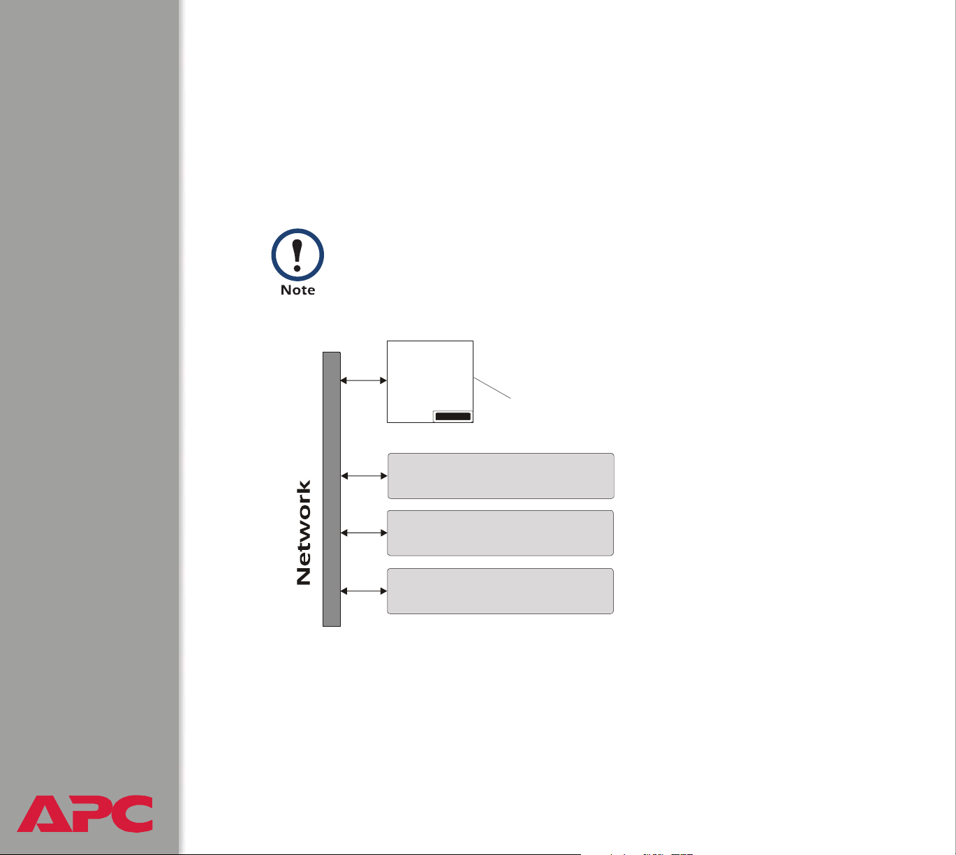
The Management Card can perform a variety of tasks. The figure that
follows identifies and briefly describes the network management
applications that can work with a DC Power Plant that connects to the
network through the Management Card.
The APC Management Card Wizard identified in the
following figure can be used to configure multiple
Management Cards, either serially or over the network. It
cannot be used to download firmware upgrades.
UDP
FTP
HTTP
SNMP
DC Power
Plant
The Management Card connects the DC Power Plant to the network.
SNMP
HTTP
USER’S GUIDE
network management card
®
MIB Browser
Web Browser
FTP
Management Card Wizard
Uses SNMP OIDs to provide SETs and
G on a DC Power Plant.ETs
Provides a graphical UI to the DC
Power Plant through a standard Web
browser.
Configures multiple Management Cards
over a network.
2
Page 5

Internal Management Features
Overview
The Management Card has two internal interfaces (control console and
Web interface) which provide menus with options that allow you to manage
the DC Power Plant and the Management Card. The Management Card’s
SNMP interface also allows you to use an SNMP browser with the
®
PowerNet
Plant.
Management Information Base (MIB) to manage the DC Power
For more information about the Management Card’s internal user
interfaces, see Control Console and Web Interface.
To use the PowerNet MIB with an SNMP browser, see the
®
PowerNet
SNMP Management Information Base (MIB)
See also
Reference Guide (\doc\en\Dcmibgde.pdf), which is provided on
the APC Network Management Card utility CD.
Access priority for logging on
Only one user at a time can log onto the Management Card to use its
internal user interface features. The priority for access is as follows:
• Local access to the control console from a computer with a direct serial
connection to the Management Card always has the highest priority.
• Telnet access to the control console from a remote computer has
priority over Web access.
• Web access either directly or through the InfraStruXure Manager (for
InfraStruXure-compatible products), has the lowest priority.
USER’S GUIDE
network management card
®
f
For information about how SNMP access to the Management
Card is controlled, see SNMP.
3
Page 6

Types of user accounts
The Management Card has two levels of access (Administrator and Device
Manager), both of which are protected by Password and User Name
requirements.
• An Administrator can use all of the management menus available in
the control console and the Web interface. The Administrator’s default
User Name and Password are both apc.
• A Device Manager can use only these menus:
–The Device Manager menu and its sub-menus in the control
console, and all menus in the top section of the navigation panel of
the Web Interface (System, Power Modules, Distribution,
Batteries, I/O)
– the Log option in the Events menu and in the Data menu in the
Web interface. (A Device Manager can also access the Event Log in
the control console by pressing
A Device Manager cannot access the Network menu or the System
menu that are in the second part of the navigation panel in the Web
interface and are sub-menus of the main Control Console menu in
CTRL-L)
the control console.
The Device Manager’s default User Name is device, and the default
Password is apc.
For information about how to set Administrator and Device
Manager User Name and Password settings, see User
Manager.
USER’S GUIDE
network management card
®
4
Page 7
Front Panel
Introduction
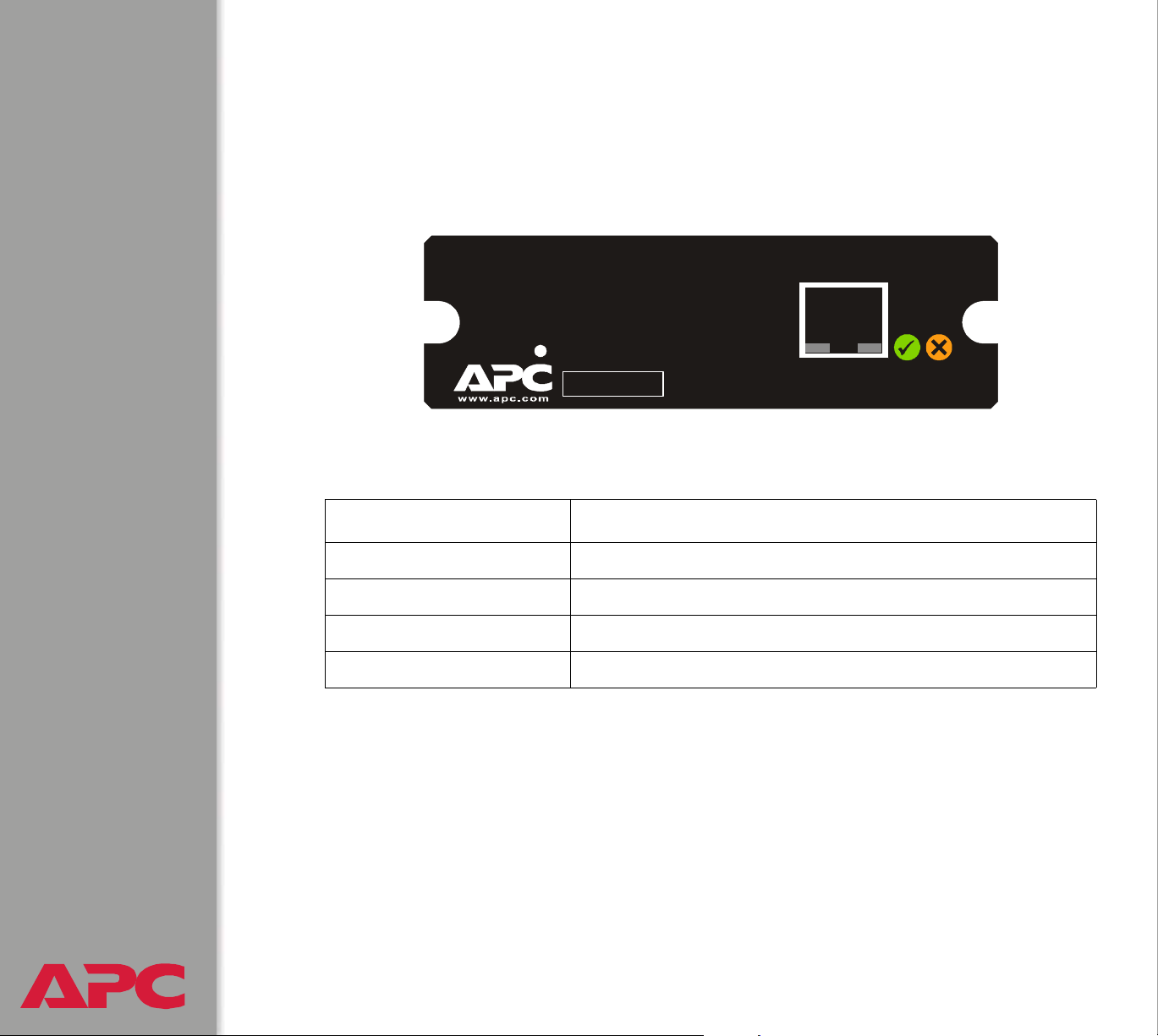
The front-panel features of the Network Management Card (AP9617)
include Status LEDs, a Reset button, and a 10/100Base-T connector.
10/100Base-T
m
Features
Feature Description
Reset button Resets the Management Card while power remains on.
10/100 Base-T connector Connects the Management Card to the Ethernet network.
Link-RX/TX (
Status LEDs See Status LEDs.
Reset
Smart Slot
10/100) LED See Link-RX/TX (10/100) LED.
Link - RX/TX Status
10
100
/
AP9617 Network Management Card EX
USER’S GUIDE
network management card
®
5
Page 8

Link-RX/TX (
This LED indicates the network status.
Condition Description
Off Either the Management Card is receiving no network traffic, or the
Flashing Green The Management Card is receiving data packets from the network
Flashing Orange The Management Card is receiving data packets from the network
10/100
) LED
device which connects the Management Card to the network is
turned off or not operating correctly.
at 10 Megabits per second (Mbps).
at 100 Megabits per second (Mbps).
Status LEDs
These LEDs indicate the Management Card’s status.
Condition Description
Off The Management Card has no power.
Solid Green The Management Card has valid TCP/IP settings.
Flashing Green The Management Card does not have valid TCP/IP settings.
Solid Orange A hardware failure has been detected in the Management Card.
Contact APC Worldwide Customer Support.
Flashing Orange The Management Card is making BOOTP
1.If you do not use a BOOTP server, see the Network Management Card Quick-Start Manual
(.\doc\en\Qckguide) provided in printed format and in PDF on the APC Network Management
Card utility CD
settings.
2.To use a BOOTP server, see the Management Card Addendum (.\doc\Addendum.pdf) on the
APC Network Management Card utility CD.
USER’S GUIDE
network management card
®
for information about how to configure the Management Card’s TCP/IP
1
2
requests.
6
Page 9

Watchdog Features
Overview
To detect internal problems and recover from unanticipated inputs, the
Management Card uses internal, system-wide watchdog mechanisms.
When it reboots itself to recover from an internal problem, a System:
Warmstart event is recorded in the Event Log.
Network interface watchdog mechanism
The Management Card implements internal watchdog mechanisms to
protect itself from becoming inaccessible over the network. For example, if
the Management Card does not receive any network traffic for 9.5 minutes
(either direct traffic, such as SNMP, or broadcast traffic, such as an Address
Resolution Protocol [ARP] request), it assumes that there is a problem with
its network interface and reboots itself.
Resetting the network timer
To ensure that the Management Card does not reboot if the network is quiet
for 9.5 minutes, the Management Card attempts to contact the Default
Gateway every 4.5 minutes. If the gateway is present, it responds to the
Management Card, and that response restarts the 9.5-minute timer. If your
application does not require or have a gateway, specify the IP address of a
computer that is running on the network most of the time and is on the same
subnet. The network traffic of that computer will restart the 9.5-minute timer
frequently enough to prevent the Management Card from rebooting.
USER’S GUIDE
network management card
®
7
Page 10
Control Console
How To Log On
Overview
You can use either a local (serial) connection, or a remote (Telnet)
connection with a computer on the Management Card’s subnet to access
the control console.
Use case-sensitive User Name and Password entries to log in (by default,
apc and apc, for an Administrator, or device and apc, for a Device
Manager).
If you cannot remember your User Name or Password, see
How to Recover from a Lost Password.
Remote access to the control console
You can use Telnet to log into the control console from any computer on the
same subnet as the Management Card.
1. At a command prompt, type telnet and the Management Card’s
System IP address, and then press
telnet 139.225.6.133
2. Enter your User Name and Password.
USER’S GUIDE
network management card
®
ENTER. For example:
8
Page 11

Local access to the control console
You can use a local computer that connects to the Management Card
through the Management Card’s serial port. The type of cable to use
depends on the location of the Management Card in the DC Power Plant:
• Type 1: The Management Card is an integrated part of the DC System
Controller. The DC System Controller front panel has the following
connectors:
– A female DB-9 connector for connection to the control console.
– An RJ-45 10/100BaseT connector for connection to the network.
For Type 1 equipment, use the straight-through serial cable (940-0085
or 0129-6) supplied with the DC Power Plant.
• Type 2: The Management Card is not a part of the DC System
Controller. It is installed separately from the controller. The female
DB-9 connector for connection to the control console is next to the
Management Card.
For Type 2 equipment use a smart-signaling (advanced signaling)
cable (940-0024 or 940-1524) supplied with the DC Power Plant.
To connect Type 1 equipment:
1. Select a serial port at the local computer, and disable any service that
uses that port.
2. Use the Type 1 cable (940-0085 or 0129-6) to connect the selected
port to the serial port on the DC System Controller.
USER’S GUIDE
network management card
®
9
Page 12

To connect Type 2 equipment:
1. Select a serial port at the local computer, and disable any service that
uses that port.
2. Use the smart-signaling (advanced signaling) cable (940-0024 or
940-1524) to connect the selected port to the serial port on the
mounting bracket of the Management Card.
Do not attach the cable to the serial port on the front panel of
the DC System Controller
To continue the procedure for either type of equipment:
3. Run a terminal program (such as HyperTerminal
selected port for 2400 bps, 8 data bits, no parity, 1 stop bit, and no flow
control, and save the changes.
®
), and configure the
4. Press
5. Enter your user name and, at the Password prompt, your password.
USER’S GUIDE
network management card
®
ENTER to display the User Name prompt.
10
Page 13

How to Recover from a Lost Password
You can use a local computer that connects to the Management Card
through the serial port at the Management Card’s mounting bracket to
access the control console.
1. Select a serial port at the local computer, and disable any service
which uses that port.
2. Use the type 1 or type 2 serial cable as described in Local access to
the control console to connect the selected port to the Management
Card’s serial port.
®
3. Run a terminal program (such as HyperTerminal
selected port for 2400 bps, 8 data bits, no parity, 1 stop bit, and no flow
control, and save the changes.
), and configure the
4. Press
5. Press the Reset button on the Management Card, which causes the
Management Card to restart, a process that typically takes
approximately 15 seconds.
6. Press
prompt, then use apc for the user name and password. (If you take
longer than 30 seconds to log on after the User Name prompt is
redisplayed, you must start the login procedure again at step 4.)
7. From the Control Console menu, select System, then User
Manager.
8. Select Administrator, and change the User Name and Password
settings, both of which are now defined as apc.
9. Press
USER’S GUIDE
network management card
ENTER to display the User Name prompt.
ENTER as many times as necessary to redisplay the User Name
CTRL-C and log off.
Reconnect any cable that you disconnected in step 2 and
restart any service that you disabled in step 1.
®
11
Page 14

Main Screen
Example main screen
The following is an example of the screen that appears when you log onto
the control console at a Network Management Card (AP9617).
User Name: apc
Password : ***
American Power Conversion Network Management Card AOS v1.0.7
<c> Copyright 2004 All Rights Reserved MX28B DC APP v1.1.1
------------------------------------------------------------------------------Name : Plant1 Date: 04/15/2004
Contact : Tom_Adams Time: 05:49:30
Location : TestLab User: Administrator
Up Time : 1 Day 4 Hours 5 Minutes Stat: P+ N+ A+
DC Power Plant : No Alarms Present
-------- Control Console ------------------------------------------------------
1- Device Manager
2- Network
3- System
4- Logout
<ESC>- Main Menu, <ENTER>- Refresh, <CTRL-L>- Event Log
>
USER’S GUIDE
network management card
®
12
Page 15

Information and status fields
Main screen information fields.
• Two fields identify the APC operating system (AOS) and application
(APP) firmware versions. The application firmware uses a name that
identifies the type of DC Power Plant that the Management Card
connects to the network. In the Example main screen, the
Management Card uses the application firmware for the DC Power
Plant.
Network Management Card AOS v1.0.7
MX28B DC APP v1.1.1
• Three fields identify the system Name, Contact, and Location values.
Name : Plant1
Contact : Tom_Adams
Location : TestLab
To set the Name, Contact, and Location values, see
System Menu.
•An Up Time field reports how long the Management Card has been
running since it was last turned on or reset.
Up Time : 1 Day 4 Hours 5 Minutes
• Two fields identify when you logged on, by Date and Time.
Date : 04/15/2004
Time : 05:49:30
•A User field identifies whether you logged on as an Administrator or
Device Manager.
User : Administrator
USER’S GUIDE
network management card
®
13
Page 16

Main screen status fields.
•A Stat field reports the Management Card status.
Stat : P+ N+ A+
P+ The APC operating system (AOS) is functioning properly.
N+ The network is functioning properly.
N? A BOOTP request cycle is in progress.
N– The Management Card failed to connect to the network.
N! Another device is using the Management Card’s IP address.
A+ The application is functioning properly.
A– The application has a bad checksum
A? The application is initializing
A! The application is not compatible with the AOS.
If the AOS status is not P+, contact APC Worldwide
Customer Support, even if you can still access the
Management Card.
•A DC model and name field reports the status of the DC Power Plant.
For example:
DC Power Plant : No Alarms Present
USER’S GUIDE
network management card
®
14
Page 17

Control Console Menus
Overview
The control console dynamically expands to provide options that you use to
manage a Management Card and the DC Power Plant.
Main menu
The main Control Console menu has options that provide access to the
control console’s management features:
1- Device Manager
2- Network
3- System
4- Logout
s
When you log on as Device Manager, you can access only
the Device Manager menus and the Logout menu.
USER’S GUIDE
network management card
®
15
Page 18

Menu structure
The menus in the control console list options by number and name. To use
an option, type the option’s number and press
screen instructions.
Some options access a new menu; other options allow you to change a
setting. Menus that allow you to change a setting have an Accept Changes
option which you must use before you exit a menu to save the changes you
made.
While in a menu, you can also do the following:
ENTER, then follow any on-
•Type
the menu has help available)
• Press
• Press
current menu
• Press
• Press
? and press ENTER, to access brief menu option descriptions (if
ENTER, to refresh the menu
ESC, to go back to the menu from which you accessed the
CTRL-C, to return to the main (Control Console) menu
CTRL-L, to access the Event Log.
For information about the Event Log, see Event-Related
Menus.
Device Manager option
This option accesses the Device Manager menu. This menu’s options
allow you to select the device that you want to manage. For example:
1- DC Power Plant
USER’S GUIDE
network management card
®
16
Page 19

Network option
To do any of the following tasks, see Network Menu:
• Configure the Management Card’s TCP/IP settings.
• Use the Ping utility
• Define settings that affect the Management Card’s FTP, Telnet, Web
interface, SNMP, e-mail, and DNS features
System option
To do any of the following tasks, see System Menu:
• Control Administrator and Device Manager access
• Define the system Name, Contact, and Location values
• Set the Date and Time used by the Management Card
• Reboot the Management Card
• Reset control console settings to their default values
• Access system information about the Management Card
USER’S GUIDE
network management card
®
17
Page 20

Web Interface
Introduction
Overview
The Web interface provides options that you use to manage a Management
Card and the DC Power Plant.
Web menu options
Two Web menu options affect access to the Web interface.
• Access: Enables (by default) or disables the Web interface.
• Port: Defines the Web-server port (80, by default) used for the Web
interface.
For more information about the Access and Port options, see
FTP Server, and Telnet & Web options.
USER’S GUIDE
network management card
®
18
Page 21

Supported Web browsers
As your browser, you can use Microsoft® Internet Explorer (IE) 5.0 (and
®
higher) or Netscape
through its Web interface.
Some Web interface features (data verification, Event Log, and Data Log)
require that you enable the following for your Web browser:
• JavaScript
•Java
• Cookies
In addition, the Management Card cannot work with a proxy server.
Therefore, before you can use a Web browser to access its Web interface,
you must do one of the following:
• Configure the Web browser to disable the use of a proxy server for the
Management Card
• Configure the proxy server so that it does not proxy the specific IP
4.0.8 (and higher) to access the Management Card
address of the Management Card
USER’S GUIDE
network management card
®
19
Page 22

How to Log On
Overview
You can use a Management Card’s DNS name or System IP address for
the URL address of the Web interface. Use your case-sensitive User Name
and Password settings to log on (by default, apc and apc, for an
Administrator, or device and apc, for a Device Manager).
For information about the Web page that appears when you
log onto the Web interface, see Summary Page.
USER’S GUIDE
network management card
®
20
Page 23

URL address formats
Type the Management Card’s DNS name or IP address in the Web
browser’s URL address field and press
http:// is automatically added by the browser.
If the error “You are not authorized to view this page” occurs
(Internet Explorer only), someone is logged onto the Web
interface or control console. If the error “No Response”
(Netscape) or “This page cannot be displayed” (Internet
Explorer) occurs, Web access may be disabled, or the
Management Card may use a non-default Web-server port
that you did not specify correctly in the address.
For more information, see FTP Server, and Telnet & Web
options.
• For a DNS name of Web1, the entry would be:
http://Web1
ENTER. Except as noted below,
• For a System IP address of 158.205.12.114, when the Management
Card uses the default port (80) at the Web server, the entry would be:
http://158.205.12.114
• For a System IP address of 158.205.12.114, when the Management
Card uses a non-default port (5000, in this example) at the Web server,
the entry would be:
http://158.205.12.114:5000
For Internet Explorer, you must type http:// as part of the
address when any port other than 80 is used. Omitting
http://causes the error “This page cannot be displayed.”
For more information, see FTP Server, and Telnet & Web
USER’S GUIDE
network management card
®
options.
21
Page 24
Summary Page
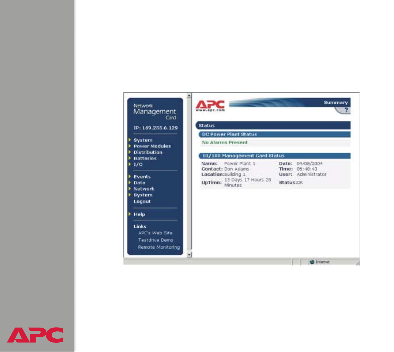
Example Web page
The following is an example of the navigation menu (see Navigation Menu)
and Summary page that appear when you log onto the Web interface at a
Network Management Card.
USER’S GUIDE
network management card
®
22
Page 25

Summary page fields
The Summary page has two sections:
•The DC section reports the status of a connected DC Power Plant.
• The Management Card section reports the following information:
–The Name, Contact and Location information for the Management
Card
– The login Date and Time
– Type of User (Administrator or Device Manager)
– How long (Up Time) the Management Card has been continuously
running since it was turned on or reset
–The Status of the Management Card
Help icon on quick status tab
Click on the question mark (?) in the quick status tab in the upper-right
corner of any Web interface page to access the online help for that page.
USER’S GUIDE
network management card
®
23
Page 26

Navigation Menu
Overview
When you log onto the Web interface, the navigation menu (left frame)
includes the following elements:
• The Management Card’s IP address
• DC menus to manage the DC Power Plant and its components
– System menu with DC Parameters and Active Alarms as options
– Power Modules menu, with Rectifiers and Converters as options
– Distribution menu, with Breakers and Fuses as options
– Batteries menu, with Parameters and LVD as options.
– I/O menu, with Input and Output as options.
• Menus to manage the logs, network connection, system parameters
– Events menu
– Data menu
– Network menu
– System menu
When you log on as a Device Manager, the Network and
System menus do not appear in the navigation menu.
• Logout option
• Help menu
• Links menu
USER’S GUIDE
network management card
®
24
Page 27

Selecting a menu to perform a task
Use the menus to perform tasks as follows:
• To manage a DC Power Plant, see DC Power Plant & Device Manager
Menus
• To do the following, see Event-Related Menus:
– Access the Event Log
– Configure the actions to be taken based on an event’s severity level
– Configure SNMP Trap Receiver settings for sending event-based
traps
– Define who will receive e-mail notifications of events
• To do the following, see Data Menu (Web Interface Only):
– Access the Data Log
– Define the log interval (how often data will be sampled and
recorded) for the Data Log
• To do the following, see Network Menu:
– Configure new TCP/IP settings for the Management Card
– Identify the Domain Name Service (DNS) Server and test the
network connection to that server
– Define settings that affect FTP, Telnet, the Web interface, SNMP,
and E-mail
For information about how the Network menu’s Telnet/Web
option can affect access to the Web interface, see Web
menu options.
USER’S GUIDE
network management card
®
25
Page 28

• To do the following, see System Menu.
– Control Administrator and Device Manager access
– Define the system Name, Contact, and Location values
– Set the Date and Time used by the Management Card
– Reboot the Management Card
– Reset control console settings to default settings
– Select Fahrenheit or Celsius for temperature displays
– Define the URL addresses used by the Web interface’s user and
APC logo links, as described in Links menu
Help menu
When you click Help, the Contents for the online help is automatically
displayed to provide for easy navigation to a specific online help topic.
However, from any of the Web interface pages, you can use the question
mark (?) that appears in the quick status bar to link to the section of the
online help that covers that page’s content.
The Help menu also has an About System option you use to view
information about the Management Card’s Model Number, Serial Number,
Hardware Revision, Manufacture Date, MAC Address, Application
Module and APC OS (AOS) Module, including the date and time these
modules were loaded.
In the control console, the About System option, which is a
System menu option, identifies the Flash Type used.
USER’S GUIDE
network management card
®
26
Page 29

Links menu
Provides three user-definable URL link options. By default, these links
access the following APC Web pages:
• APC’s Web Site accesses the APC home page
• Testdrive Demo accesses a demonstration page where you can use
samples of APC web-enabled products
• APC Monitoring accesses the “APC Remote Monitoring Service”
page where you can find more information about pay-for-monitoring
services available from APC
You can use the following procedure to redefine these links so that they
point to other URLs.
1. Click on Links in the System menu.
2. Define any new names for the User Links.
3. Define any new URL addresses that you want the User Links to
access.
4. Click Apply.
USER’S GUIDE
network management card
®
27
Page 30

Network Menu
Introduction
Overview
The Network menu has the options that you use to do the following tasks:
• Define TCP/IP settings, including BOOTP server settings, when a
BOOTP server is used to provide the needed TCP/IP values
• Use the Ping utility
• Define settings that affect the Management Card’s FTP, Telnet, Web
interface, SNMP, e-mail, and DNS features
Only an Administrator has access to the Network menu.
Menu options
Unless noted, the following menu options are available in the control
console and Web interface:
• TCP/IP
• DNS
• Send DNS Query (Web interface only)
• Ping utility (control console)
• FTP Server, and Telnet & Web options
• SNMP
• Email
USER’S GUIDE
network management card
®
28
Page 31

Option Settings
These options are combined in the Web interface (the TCP/IP
& DNS option) but separate in the control console.
TCP/IP
Use this option to enable or disable BOOTP, and when BOOTP is disabled,
to define the three TCP/IP settings that the Management Card needs to
operate on the network.
• The Management Card’s System IP address
• The subnet mask value
• The IP address of the default gateway
For information about the watchdog role of the default
gateway, see Resetting the network timer.
When BOOTP is enabled (by default), you can affect only the BOOTP
setting: A BOOTP server will provide the Management Card with its TCP/IP
settings whenever the Management Card is turned on, reset, or rebooted.
To use BOOTP, see the Network Management Card Addendum
(.\doc\en\addendum.pdf) provided on the APC Network
See also
Current TCP/IP settings fields. The current values for System IP,
Subnet Mask, Default Gateway, and the Management Card’s MAC
Address are displayed above the TCP/IP settings in the control console
USER’S GUIDE
network management card
®
and Web interface.
Management Card utility CD.
29
Page 32

DNS
This control console option is part of the TCP/IP & DNS option in the Web
interface.
Configure Domain Name Server Settings fields. Use these fields to
define the IP addresses of the primary and secondary Domain Name
Servers (DNS) used by the Management Card’s e-mail feature.
See E-mail Feature and DNS servers.
Send DNS Query (Web interface only). Use this option, available only
through the TCP/IP & DNS menu in the Web interface, to send a DNS
query that tests the setup of your DNS servers.
Use the following settings to define the parameters for the test DNS
request; you view the result of the test DNS request in the Last Query
Response field (Passed, Failed, or Not Responding).
• Use the Query Type setting to select the method to use for the DNS query:
– The URL name of the server (By Name)
– The IP address of the server (By IP)
– The Mail Exchange used by the server (By MX)
• Use the Query Question text field to specify the value to be used for the
selected Query Type:
–For Name, specify the URL
–For IP, specify the IP address
–For MX, specify the Mail Exchange address
• Use the DNS Server to Query to select whether you want to query the
USER’S GUIDE
network management card
®
Primary DNS Server or Secondary DNS Server.
30
Page 33

Ping utility (control console)
Select this option, available only in the control console, to check the
Management Card’s network connection by testing whether a defined IP
address responds to the Ping network utility.
By default, the default gateway IP address (see TCP/IP) is used. However, you
can use the IP address of any device known to be running on the network.
USER’S GUIDE
network management card
®
31
Page 34

FTP Server, and Telnet & Web options
The Telnet and Web options are combined in the Web
interface but separate in the control console.
Each of these options has a setting which enables (by default) or disables
Access, and a Port setting that identifies the TCP/IP port used for
communications with the Management Card. The default Port settings are 21
(FTP), 23 (Telnet), and 80 (Web interface).
To enhance the protection provided by User Name and Password settings,
change the Port setting to a unique port number from 5000 to 65535. After
this change, when you log on, you must add a colon (:) and the non-default
Port number to the IP address used. The following examples show the FTP,
Telnet, and Web interface commands needed when the Port numbers have
been changed to 5000 for FTP, 59401 for Telnet, and 65002 for HTTP at a
management card with a System IP address of 159.215.12.114:
ftp 159.215.12.114:5000
telnet 159.215.12.114:59401
http://159.215.12.114:65002
To use FTP to download configuration files, see the Management
Card Addendum (.\doc\en\addendum.pdf) on the APC Network
See also
USER’S GUIDE
network management card
®
Management Card utility CD.
To use FTP to access a text version of the Management Card’s Event
Log or Data Log, see How to use FTP to retrieve log files.
32
Page 35

SNMP
An Access option (the Settings option in the control console) enables (by
default) or disables SNMP. When SNMP is enabled, the Access Control
settings allow you to control how each of the four available SNMP channels
is used.
To define up to four NMSs to serve as trap receivers, see
Trap Receiver settings.
Setting Definition
Community
Name
NMS IP Limits access to the NMS or NMSs specified by the format used for the
Defines the password (maximum of 15 characters) which an NMS that is
defined by the NMS IP setting below uses to access the channel.
IP address.
• 162.245.12.1 allows only the NMS with that IP address to have access.
• 162.245.12.255 allows access for any NMS on the 162.245.12 segment.
• 162.245.255.255 allows access for any NMS on the 162.245 segment.
• 162.255.255.255 allows access for any NMS on the 162 segment.
• 0.0.0.0 or 255.255.255.255 allows access for any NMS.
USER’S GUIDE
network management card
®
33
Page 36

Setting Definition
Access
Type
Selects how the NMS defined by the NMS IP setting can use the channel,
when that NMS uses the correct Community Name.
Read The NMS can use GETs at any time, but it can never use
SETs.
Write The NMS can use GETs at any time, and can use SETs
when no one is logged onto either the control console or
Web interface.
Disabled The NMS cannot use GETs or SETs.
Write+ The NMS can use GETs and SETs at any time, even
when someone is logged onto the control console or
Web interface.
Use this option to define two SMTP settings (SMTP Server and From
Address) used by the Management Card’s e-mail feature.
For more information about these settings, see SMTP settings; for more
information about e-mail as it relates to the Management Card, see E-mail
Feature.
USER’S GUIDE
network management card
®
34
Page 37

System Menu
Introduction
Overview
The System menu has the options that you use to do the following tasks:
• Configure system identification, date and time settings, and
Administrator and Device Manager access
• Synchronize the Management Card’s real-time clock with a Network
Time Protocol (NTP) server
• Download configuration files
• Reset or reboot the Management Card
• Define the URL links available in the Web interface
• Access hardware and firmware information about the Management
Card
• Set the units (Fahrenheit or Celsius) used for temperature displays
Only an Administrator has access to the System menu.
USER’S GUIDE
network management card
®
35
Page 38

Menu options
Unless noted, the following menu options are available in the control
console and Web interface:
• User Manager
• Identification
• Date & Time
• Too ls
• Preferences (Web interface)
• Links (Web interface)
• About System
The About System option is a Help menu option in the Web
interface.
USER’S GUIDE
network management card
®
36
Page 39

Option Settings
User Manager
Use this option to define the access values shared by the control console
and the Web interface.
Setting Definition
Auto Logout The number of minutes (3, by default), before a user is
automatically logged off because of inactivity.
Administrator and Device Manager User
User Name Defines the case-sensitive name (maximum of 10 characters) used
to log onto the control console or Web interface (apc, by default, for
Administrator, and device, by default, for Device Manager User).
Password Defines the case-sensitive password (maximum of 10 characters).
apc is the default for both Password settings.
Identification
Use this option to define the System Name, Contact, and Location values
used by the Management Card’s SNMP agent. The option’s settings
provide the values used for the MIB-II sysName, sysContact, and
sysLocation Object Identifications (OIDs).
For more information about the MIB-II OIDs, see the PowerNet®
SNMP Management Information Base (MIB) Reference Guide
See also
USER’S GUIDE
network management card
®
(.\doc\en\Dcmibgde.pdf) provided on the APC Network
Management Card utility CD.
37
Page 40

Date & Time
Use this option to set the time and date used by the Management Card. The
option displays the current settings, and allows you to change those
settings manually, or through a Network Time Protocol (NTP) Server.
Set Manually. Use this option in the Web interface, or Manual in the
control console, to set Date and Time for the Management Card.
An Apply Local Computer Time to Network Management
Card option, which is available in the Web interface only,
sets these values to match the date and time settings of the
computer you are using to access the Web interface.
Synchronize with Network Time Protocol (NTP) Server
which is called Network Time Protocol (NTP) in the control console, to
have an NTP Server automatically update the Date and Time settings for
the Management Card.
In the control console, use the NTP Client option to enable
or disable (the default) the NTP Server updates. In the Web
interface, use the Set Manually option to disable the
updates.
Setting Definition
Primary NTP Server Identifies the IP address of the primary NTP server.
Secondary NTP Server Identifies the IP address of the secondary NTP server,
when a secondary server is available.
TIme Zone Defines the offset to be used from Greenwich Mean TIme
(GMT) based on the Management Card’s time zone.
Update Interval Defines how often, in weeks, the Management Card will
USER’S GUIDE
network management card
®
access the NTP Server for an update (1 week minimum,
52 weeks maximum). Use Update Using NTP Now to
initiate an immediate update as well.
. Use this option,
38
Page 41

Tools
Use this option to reboot the Management Card or to reset some or all of its
configuration settings to their original, default values.
Action Definition
Reboot Restarts the Management Card.
Reset to Defaults Resets all configuration settings.
Reset to Defaults Except
TCP/IP
XMODEM (control
console only)
Resets all configuration settings except the TCP/IP
settings.
Allows you to download firmware using a terminalemulation program when you use a local connection to the
control console only. To connect to the control console
locally, see Local access to the control console.
Preferences (Web interface)
Use this option to define whether temperature values are displayed as
Fahrenheit or Celsius in the Web interface and the control console.
USER’S GUIDE
network management card
®
39
Page 42

Links (Web interface)
Use this option to modify the links to APC Web pages.
Setting Definition
User Links
Name Defines the link names that appear in the Links menu (by default,
APC’s Web Site, Testdrive Demo, and Remote Monitoring).
URL Defines the URL addresses used by the links. By default, the
following URL addresses are used:
• http://www.apc.com (APC’s Web Site)
• http://testdrive.apc.com (Testdrive Demo)
• http://rms.apc.com (Remote Monitoring)
N
OTE:For information about these pages see Links menu.
Access Links
APC Home Page Defines the URL address used by the APC logo at the top of all Web
interface pages (by default, http://www.apc.com).
About System
This option identifies hardware information for the Management Card,
including its Model Number, Serial Number, Hardware Revision,
Manufacture Date, MAC Address, and Flash Type.
This information is set at the factory and cannot be changed.
In the Web interface, except for Flash Type, this hardware
information is reported by the About System option in the
Help menu.
USER’S GUIDE
network management card
®
40
Page 43

DC Power Plant & Device Manager Menus
Status Options
System and battery status
To display system and battery status, do either of the following:
• In the Web interface, select the DC Parameters option of the first
menu item (System)
• In the control console, select, in order, Device Manager, DC Power
Plant, DC System, and DC System Parameters.
USER’S GUIDE
network management card
®
41
Page 44

Web interface. The Web interface displays the DC Power Plant page.
USER’S GUIDE
network management card
®
42
Page 45

Control Console. The DC Power Plant screen displays the same status
information as the DC Power Plant page of the Web interface.
DC System Voltage (V) : -54.30
DC System Current (A) : 0.21
DC System Temperature(degC) : 32.90
Battery Current (A) : 0.014
Battery Temperature (degC) : 30.11
Battery Float Voltage (V) : -58.00
Battery Max Recharge (A) : 50.00
In the control console only, you can set alarm thresholds for the last two
values. See the description of the first two menu items on the Battery
Thresholds submenu: 1- Float Voltage and 2- Max Recharge. (For the
Battery Thresholds submenu, select, in order, Device Manager, DC
Power Plant, DC System, Batteries.)
USER’S GUIDE
network management card
®
43
Page 46

Management Options
DC Power Plant options
Control Console and Web Interface. To access the following menu
options to manage the DC Power Plant:
• In the control console, select Device Manager and DC Power Plant.
• In the Web interface, use the menus in the top section of the navigation
panel.
Control Console Web interface Link to Description
1 - DC System System>DC
Parameters
2 - Power Modules Power Modules Power Modules: Rectifiers and
3 - Distribution Distribution Distribution: Breakers and Fuses
4 - Batteries Batteries>Parameters Batteries: Status, Thresholds and
5 - Relays I/O Relays: Output Relays and Input
6 - LVD Batteries>LVD LVD (Low Voltage Disconnect)
7 - Power Plant
Alarms/
Internal Log
8 - About DC
Power System
In the Web interface, you display Power Plant alarms by
System>Active
Alarms (Internal Log
not available)
not available About DC Power Plant System
DC System: DC System
Parameters & OEM Parameters
Converters
Alarms
Relays
Power Plant Alarms/Internal Log
USER’S GUIDE
network management card
®
selecting Active Alarms from the first menu (System) in the
navigation panel.
44
Page 47

DC System: DC System Parameters & OEM Parameters
Web Interface. DC System Parameters are displayed at the bottom of the
DC Power Plant page, which you access by selecting DC Parameters at
the first menu (System) in the navigation panel. At the bottom of the page
are two links:
• To configure the DC System Parameters, click Configure.
• To display OEM Parameters, click View OEM Parameters.
For descriptions of the parameters, see Control Console.
USER’S GUIDE
network management card
®
45
Page 48

Control Console. From Device Manager, type 1 to select DC Power
Plant, then type
1 again to select DC System. The following options are
displayed.
1- DC System Parameters
2- OEM Parameters
From the DC System menu, type 1 to select DC System Parameters,
which displays the following menu items:
Menu Item Description
1- Description1 Descriptions related to your DC Power Plant system.
2- Description2
3- Description3
4- High
Temperature
5- High
Temperature
Alarm
6- Low
Temperature
7-
Low
Temperature
Alarm
a
Standard alarm selections
•Major activates the major relay.
•Minor activates the minor relay.
•Relay 1 through Relay 6 activates the relay specified.
•Ignore ignores the alarm.
Maximum per field: 16 characters.
The ambient high temperature threshold.
Minimum: 0 ° Celsius
Maximum: 100.00° Celsius
The alarm action to occur when the ambient high temperature
threshold (item 4 above) is violated.
Allowed values: any standard alarm selection.
The ambient low temperature threshold.
Minimum: – 100.00° Celsius
Maximum: 100.00° Celsius
The alarm action to occur when the ambient low temperature
threshold (item 6 above) is violated.
Allowed values: any standard alarm selection.
a
a
USER’S GUIDE
network management card
®
46
Page 49

Menu Item Description
8- Hardware
Temperature
Alarm
9- Remote
Configurability
Accept Changes Use this option to save your changes.
a
Standard alarm selections
•Major activates the major relay.
•Minor activates the minor relay.
•Relay 1 through Relay 6 activates the relay specified.
•Ignore ignores the alarm.
The alarm action to occur in response to any of the following
• No temperature probe cable is connected
• A faulty temperature probe cable is connected
• The temperature probe itself is faulty.
This alarm action occurs only if temperature compensation is
enabled. See Battery Thresholds.
a
Allowed values: any standard alarm selection.
Disables remote write access to the DC Power Plant. You can reenable access only from the DC Power Plant’s front panel.
From the DC System menu, type 2 to select OEM Parameters, which
displays the following calibration parameters, which are set at the factory
and cannot be changed:
Menu Item Description
Rectifier Offset Rectifier offset adjustment in volts.
Rectifier Gain Rectifier measurement gain adjustment.
Converter
Offset
Converter Gain Converter measurement gain adjustment.
Shunt Offset Battery shunt offset adjustment in amps.
USER’S GUIDE
network management card
®
Shunt Gain Battery shunt measurement gain adjustment.
Converter offset adjustment in volts.
47
Page 50

Power Modules: Rectifiers and Converters
From the Device Manager menu, type 1 to select DC Power Plant. Then
2 to select Power Modules. The following options are displayed.
type
1- Rectifiers
2- Converters
Each option has sub-menus for parameters, alarms, and status.
Rectifiers. From the Rectifiers sub-menu, type 1 for configurable Rectifier
Parameters.
Rectifier Parameters Description
1- High Voltage Threshold (V) If rectifier voltage exceeds this value, a rectifier high
voltage alarm occurs. To set the alarm action, see
Rectifier Alarms.
2- Low Voltage Threshold (V) If rectifier voltage drops below this value, a rectifier low
voltage alarm occurs. To set the alarm action, see
Rectifier Alarms.
3- Fail Safe (V) The value sent to rectifier controllers to use if
communication is lost with the master controller or if
the master controller board fails.
4- Communications Fail (sec) The time in seconds (60 by default) that a rectifier
waits for communication with the master controller
before resetting all its values to their defaults.
5- Accept Changes Use this option to save your changes.
USER’S GUIDE
network management card
®
48
Page 51

From the Rectifiers sub-menu, type 2 for configurable Rectifier Alarms:
Rectifier Alarms Description
1- High Voltage
Alarm
2- Low Voltage
Alarm
3- Configuration
Alarm
4- 1 of N Alarm The alarm action that occurs if one rectifier fails in a DC Power
5- 2 of N Alarm The alarm action that occurs if two or more rectifiers fail.
6- Diagnostic
Alarm
The alarm action that occurs if the High Voltage Threshold has
been violated. See Rectifier Parameters.
a
Allowed values: any standard alarm selection
The alarm action that occurs if the Low Voltage Threshold has been
violated. See Rectifier Parameters.
Allowed values: any standard alarm selection
The alarm action that occurs if a new rectifier is detected that was
not present when the system was rebooted or powered on.
Allowed values: any standard alarm selection
Plant with multiple rectifiers
Allowed values: any standard alarm selection
Allowed values: any standard alarm selection
The alarm action that occurs in response to a diagnostic alarm for
the rectifier controller.
Allowed values: any standard alarm selection
.
a
.
a
.
a
.
a
.
a
or n of Nb.
7- Imbalance
Alarm
a
Standard alarm selections:
• Major activates the major relay.
• Minor activates the minor relay.
• Relay 1 through Relay 6 activates the relay specified.
• Ignore ignores the alarm.
b
USER’S GUIDE
network management card
®
n of N activates the alarm setting for menu item 4 (1 of N) if one rectifier fails, or
activates the alarm setting for menu item 5 (2 of N) if two or more rectifiers fail.
The alarm action that occurs for rectifier imbalance.
Allowed values: any standard alarm selection
49
a
or n of Nb.
Page 52

Rectifier Alarms Description
8- Current Limit
Alarm
9- Standby Alarm The alarm action that occurs if the control unit is holding one or
10- Fan Failure
Alarm
11- Failure Alarm The alarm action that occurs if the output of one or more rectifiers
12- Hardware
Voltage Alarm
13- Accept
Changes
a
Standard alarm selections:
• Major activates the major relay.
• Minor activates the minor relay.
• Relay 1 through Relay 6 activates the relay specified.
• Ignore ignores the alarm.
b
n of N activates the alarm setting for menu item 4 (1 of N) if one rectifier fails, or
activates the alarm setting for menu item 5 (2 of N) if two or more rectifiers fail.
The alarm action that occurs if one or more rectifiers have been
forced into the “current limited” mode.
a
Allowed values: any standard alarm selection
more rectifiers in the standby mode.
Allowed values: any standard alarm selection
The alarm action that occurs if the fan fails in one or more rectifiers.
Allowed values: any standard alarm selection
fails.
The alarm action that occurs if rectifier voltage is outside
reasonable limits or if a voltage measurement failure occurs.
Note: There is a single rectifier voltage for all rectifiers.
Allowed values: any standard alarm selection
Use this option to save your changes.
or n of Nb.
a
or n of Nb.
a
or n of N
a
.
b
USER’S GUIDE
network management card
®
50
Page 53

From the Rectifiers sub-menu, type 3 for Rectifier Status. Then at the
prompt, enter the number of a rectifier for a report of its status.
Status Field Description
Device Type The device type of the rectifier, including voltage and amperage.
All rectifiers in a DC Power Plant must be the same type.
In Standby Reports Yes if the control unit is holding the rectifier in standby
mode.
Firmware Version The firmware revision of the rectifier device.
Rect Fail Alarm Reports Yes if the rectifier has failed.
PCB Serial No. The PCB (Printed Circuit Board) serial number of the rectifier.
Rect Voltage The system-level rectifier voltage.
Self Test Result Reports whether the rectifier has passed or failed its diagnostic
testing.
Rect Current The DC output current in amps.
Fan Fail Reports Yes if the rectifier fan has failed.
Current Limit Reports Yes if the rectifier has been forced into its current-limited
mode.
USER’S GUIDE
network management card
®
51
Page 54

Converters. From the Converters sub-menu, type 1 for configurable
Converter Parameters.
Converter Parameters Description
1- High Voltage
Threshold (V)
2- Low Voltage
Threshold (V)
3- Fail Safe (V) The value sent to the converter controllers to use if
4- Set Point (V) The initial set point used in the voltage control loop.
5- Fail Max (V) The value sent to the converter controllers to define the
6- Fail Min (V) The value sent to the converter controllers to define the
7- Communications Fail
(sec)
If converter voltage exceeds this value, a converter high
voltage alarm occurs. To set the alarm action, see Converter
Alarms.
If converter voltage drops below this value, a converter low
voltage alarm occurs. To set the alarm action, see Converter
Alarms.
communication is lost with the master controller or if the
master controller board fails.
maximum set point allowed (the converter fail maximum
limit).
minimum set point allowed (the converter fail minimum
limit).
The time in seconds (60 by default) that a converter waits
for communication with the master controller before
resetting all its values to their defaults.
8- Accept Changes Use this option to save your changes.
USER’S GUIDE
network management card
®
52
Page 55

From the Converters sub-menu, type 2 for configurable Converter
Alarms.
Converter Alarms Description
1- High Voltage
Alarm
2- Low Voltage
Alarm
3- Configuration
Alarm
4- 1 of N Alarm The alarm action that occurs if one converter fails in a DC Power
5- 2 of N Alarm The alarm action that occurs if two or more converters fail.
6- Diagnostic Alarm The alarm action that occurs in response to a diagnostic alarm
The alarm action that occurs if the High Voltage Threshold has
been violated. See Converter Parameters.
a
Allowed values: any standard alarm selection
The alarm action that occurs if the Low Voltage Threshold has
been violated. See Converter Parameters.
Allowed values: any standard alarm selection
The alarm action that occurs if a new converter is detected.
Allowed values: any standard alarm selection
Plant
with multiple converters.
Allowed values: any standard alarm selection
Allowed values: any standard alarm selection
for the converter controller.
Allowed values: any standard alarm selection
.
a
.
a
.
a
.
a
.
a
or n of Nb.
7- Imbalance Alarm The alarm action that occurs for converter imbalance.
Allowed values: any standard alarm selection
a
Standard alarm selections:
Major activates the major relay.
Minor activates the minor relay.
Relay 1 through Relay 6 activates the relay specified.
Ignore ignores the alarm.
b
n of N activates the alarm setting for menu item 4 (1 of N) if one converter fails, or
USER’S GUIDE
network management card
®
activates the alarm setting for menu item 5 (2 of N) if two or more converters fail.
53
a
or n of Nb.
Page 56

Converter Alarms Description
8- Current Limit
Alarm
9- Standby Alarm The alarm action that occurs if one or more of the converters are
10- Fan Failure
Alarm
11- Failure Alarm The alarm action that occurs if the output of one or more
12- Hardware
Voltage Alarm:
13- Accept Changes Use this option to save your changes.
a
Standard alarm selections:
The alarm action that occurs if one or more converters have
been forced into the “current limited” mode.
a
Allowed values: any standard alarm selection
in standby mode.
Allowed values: any standard alarm selection
The alarm action that occurs if the fan fails in one or more
converters.
Allowed values: any standard alarm selection
converters fails.
The alarm action that occurs if converter voltage is outside
reasonable limits or if a voltage measurement failure occurs.
Note: There is a single converter voltage for all converters.
Allowed values: any standard alarm selection
or n of Nb.
a
or n of Nb.
a
or n of Nb.
a
.
Major activates the major relay.
Minor activates the minor relay.
Relay 1 through Relay 6 activates the relay specified.
Ignore ignores the alarm.
b
n of N activates the alarm setting for menu item 4 (1 of N) if one converter fails, or
activates the alarm setting for menu item 5 (2 of N) if two or more converters fail.
USER’S GUIDE
network management card
®
54
Page 57

From the Converters sub-menu, type 3 for Converter Status. Then at the
prompt, enter the number of a converter for a report of its status.
Status Field Description
Device Type The device type of the converter.
In Standby Reports Yes if the control unit is holding the converter in standby
mode.
Firmware
Version
Conv Fail
Alarm
PCB Serial No. The PCB (Printed Circuit Board) serial number of the converter.
Conv Voltage The system-level converter voltage.
Self Test Result Reports whether the converter has passed or failed its diagnostic
Conv Current The DC output current in amps.
Fan Fail Reports Yes if the converter fan has failed.
Current Limit Reports Yes if the converter has been forced into its current-limited
The firmware revision of the converter device.
Reports Yes if the converter has failed.
testing.
mode.
USER’S GUIDE
network management card
®
55
Page 58

Distribution: Breakers and Fuses
From Device Manager, type 1 to select DC Power Plant. Then type 3 to
select Distribution. The following options are displayed.
1- Breakers (range of numbers)
2- Fuses (range of numbers)
From the Distribution sub-menu, type 1 for Breakers or 2 for Fuses. Then
at the prompt, enter the number of a distribution breaker or fuse to display
its state (open or closed), its configurable name, and its configurable alarm
setting.
• The name can be up to 16 characters.
• You can specify any of the standard alarm settings:
– Major activates the major relay.
– Minor activates the minor relay
– Relay 1 through Relay 6 activates the relay specified.
– Ignore ignores the alarm.
USER’S GUIDE
network management card
®
56
Page 59

Batteries: Status, Thresholds and Alarms
From Device Manager, type 1 to select DC Power Plant. Then type 4 to
select Batteries. The following options are displayed.
1- Battery Status
2- Battery Thresholds
3- Battery Alarms
Battery Status. From the Batteries sub-menu, type 1 for Battery Status:
Menu Item Description
Float Voltage (V) The DC Power Plant voltage, in volts. To set this value, see
Battery Thresholds.
Maximum Recharge (A) The battery maximum recharge rate, in amps. To set this
value, see Battery Thresholds.
Amp/Hour Capacity (AHr) Battery amp-hour size. To set this value, see Battery
Thresholds.
Compensation Temp
Coefficient (mV/degC/cell)
High Knee Temperature
(0V/degC/cell)
Low Knee Temperature
(0V/degC/cell)
Current (A) The battery current, in amps.
Temperature The battery temperature, in degrees Celsius.
Current Sane Indicates, by yes or no, whether battery current is within an
USER’S GUIDE
network management card
®
Temperature Sane Indicates, by yes or no, whether battery temperature is within
Compensation temperature coefficient, in millivolts. To set this
value, see Battery Thresholds.
The temperature (in Celsius) above which Float Voltage no
longer changes to compensate for increase in temperature. To
set this value, see Battery Thresholds.
The temperature (in Celsius) below which Float Voltage no
longer changes to compensate for decrease in temperature. To
set this value, see Battery Thresholds.
acceptable range.
an acceptable range.
57
Page 60

Battery Thresholds. From the Batteries sub-menu, type 2 to display and
configure Battery Thresholds:
Menu Item Description
1-Float Voltage (V) The DC Power Plant voltage, in volts
Minimum: – 58.00
Maximum: – 40.00
2- Max Recharge (A) The battery maximum recharge rate, in amps.
Minimum: 0
Maximum: The maximum possible output power of your
specific DC Power Plant model.
3- Discharge Threshold (A) If battery output current exceeds this threshold (in
amps), the battery discharge alarm occurs.
Minimum: 0
Maximum: 200.00
4- High Voltage Threshold (V) If system battery voltage exceeds this threshold (in
volts), the battery high voltage alarm occurs.
Minimum: – 60.00
Maximum: – 40.00
5- Low Voltage Threshold (V) If system battery voltage drops below this threshold (in
volts, the battery low voltage alarm occurs.
Minimum: – 60.00
Maximum: – 30.00
6- High Temperature
Threshold
7- Low Temperature
Threshold
USER’S GUIDE
network management card
®
If system battery temperature in Celsius exceeds this
threshold, the battery high temperature alarm occurs.
Minimum: – 100.00
Maximum:
If system battery temperature in Celsius drops below
this threshold, the battery low temperature alarm
occurs.
Minimum: – 100.00
Maximum: 200.00
200.00
58
Page 61

Menu Item Description
8- Amp Hours (AHr) The battery amp-hour size, in amp-hours.
9- Compensation Method On enables and
compensation.
10- Comp Temp Coefficient
(mV/degC/cell)
11- High Knee Temperature
(mV/degC/cell)
12- Low Knee Temperature
(mV/degC/cell)
13- Accept Changes Use this option to save your changes.
The compensation temperature coefficient, in millivolts.
Minimum: – 4.99
Maximum: 0
The temperature (in Celsius) above which Float Voltage
no longer changes to compensate for increase in
temperature.
Minimum: 0
Maximum: 100.00
The temperature (in Celsius) below which Float Voltage
no longer changes to compensate for decrease in
temperature.
Minimum: – 100.00
Maximum: 100.00
Off disables battery temperature
USER’S GUIDE
network management card
®
59
Page 62

Battery Alarms. From the Batteries sub-menu, type 3 to display and
configure Battery Alarms:
Menu Item Description
1- Discharge
Alarm
2- High Voltage
Alarm
3- Low Voltage
Alarm
4- High
Temperature
Alarm
5- Low
Temperature
Alarm
6- Hardware
Current Alarm
The alarm action that occurs if battery output current exceeds the
Discharge Threshold. See Battery Thresholds.
a
Allowed values: any standard alarm selection
The alarm action that occurs if system battery voltage exceeds the
High Voltage Threshold. See Battery Thresholds.
Allowed values: any standard alarm selection
The alarm action that occurs if system battery voltage drops below
the Low Voltage Threshold. See Battery Thresholds.
Allowed values: any standard alarm selection
The alarm action that occurs if system battery temperature exceeds
the High Temperature Threshold. See Battery Thresholds.
Allowed values: any standard alarm selection
The alarm action that occurs if system battery temperature drops
below the Low Temperature Threshold. See Battery Thresholds.
Allowed values: any standard alarm selection
The alarm action that occurs if the battery current is outside
reasonable limits or if a measurement fault occurs.
Allowed values: any standard alarm selection
.
a
.
a
.
a
.
a
.
a
.
7- Hardware
Temperature
Alarm
a
Standard alarm selections:
• Major activates the major relay.
• Minor activates the minor relay.
• Relay 1 through Relay 6 activates the relay specified.
USER’S GUIDE
network management card
®
• Ignore ignores the alarm.
The alarm action that occurs if the battery temperature is outside
reasonable limits or if a measurement fault occurs.
Allowed values: any standard alarm selection
60
a
.
Page 63

Menu Item Description
8- Accept
Changes
a
Standard alarm selections:
• Major activates the major relay.
• Minor activates the minor relay.
• Relay 1 through Relay 6 activates the relay specified.
• Ignore ignores the alarm.
Use this option to save your changes.
USER’S GUIDE
network management card
®
61
Page 64

Relays: Output Relays and Input Relays
From Device Manager, type 1 to select DC Power Plant. Then type 5 to
select Relays. The following options are displayed.
1- Input Relays
2- Output Relays
Type 1 for a menu of Input Relays, or type 2 for a menu of Output Relays,
including the Minor and Major Relay.
From either menu, to display the status (On or Off) and the following
configurable options of a relay, type the menu option number for that relay.
Menu Item Description
1- Name The name of the relay.
Maximum: 16 characters
2- Alarm Delay
(sec)
3- Alarm Allowed values: any standard alarm selection:
USER’S GUIDE
network management card
®
4- Accept
Changes
If the condition causing the alarm clears before this delay expires,
the Management Card does not initiate the action associated with
the alarm.
Minimum: 0 seconds
Maximum: 60.00 seconds
Note: If menu item 3- Alarm is set to M
configure an alarm delay
Major activates the major relay.
Minor activates the minor relay.
Relay 1 through Relay 6 activates the relay specified.
Ignore ignores the alarm.
Note: You cannot change this value for the Major or Minor Relay.
Use this option to save your changes.
AJOR or Minor, you cannot
62
Page 65

LVD (Low Voltage Disconnect)
From Device Manager, type 1 to select DC Power Plant. Then type 6 to
select LVD.
At the prompt, enter the number of a Low Voltage Disconnect (LVD) on your
system to view the status (Opened or Closed) and to configure options for
that LVD. The following table uses LVD 1 as an example.
Menu Item (for LVD 1) Description
1- LVD 1 Name The name of the low voltage disconnect (LVD).
Maximum: 16 characters
2- LVD 1 Enable Enabled (the default) turns on the LVD. Use Disabled if no
LVD is installed.
3- LVD 1 Trip (V) Voltage above this threshold trips (opens) the LVD.
Minimum: – 58.00 Volts
Maximum:–
4- LVD 1 Reset (V) Voltage above this threshold resets (closes) the LVD.
30.00 Volts
Minimum: – 58.00 Volts
Maximum: – 30.00 Volts
5- LVD 1 Open Alarm Alarm condition indicating that the LVD is tripped (Opened).
Allowed values: any standard alarm selection
6- LVD 1 Hardware
Alarm
7- Accept Changes Use this option to save your changes.
a
Standard alarm selections:
Major activates the major relay.
USER’S GUIDE
network management card
®
Minor activates the minor relay.
Relay 1 through Relay 6 activates the relay specified.
Ignore ignores the alarm.
Alarm condition indicating that a conflict exists between the
commanded position and sensed position of the LVD.
Allowed values: any standard alarm selection
63
a
.
a
.
Page 66

Power Plant Alarms/Internal Log
From Device Manager, type 1 to select DC Power Plant. Then type 7 to
select Power Plant Alarms/Internal Log. The following options are
displayed:
1- Power Plant Status
2- Power Plant Internal Log
Alarm Status. From the Power Plant Alarms/Internal Log sub-menu,
type
1 for Power Plant Status to display the status of all DC Power Plant
alarms.
Interpret an alarm status item as follows:
• For the meaning of each active alarm status item, see the descriptions
of the alarms displayed on the Control Unit menus, as listed in your DC
Power Plant product manual.
• The last character of an alarm item is one of the following:
– The number of the relay that the alarm has activated
– m for a minor alarm
– M for a major alarm
In the following example, item 1 indicates that the System Low Voltage
Alarm is on and is a major alarm, item 3 indicates the System Low
Temperature Alarm is on and is a minor alarm, and item 4 indicates that the
Battery Low Voltage alarm is on and has activated relay 2.
1: Sys LV Alm On M
2: Load LV Alm On M
3: Sys LT Alm On m
4: Batt LV Alm On 2
5: Hdwr Batt T Alm 4
USER’S GUIDE
network management card
®
64
Page 67

Power Plant Internal Log. From the Power Plant Alarms/Internal Log
sub-menu, type
Power Plant events and the date and time at which each event occurred.
Press ENTER to scroll through earlier events. You can view this DC Power
Plant event log only in the control console, and you cannot clear this DC
Power Plant event log.
2 to display, on the first screen, the ten most recent DC
About DC Power Plant System
From Device Manager, type 1 to select DC Power Plant. Then type 8 to
select About DC Power System.
The screen displays the model, hardware revision, and firmware revision of
the DC Power Plant.
You cannot view this information in the Web interface.
USER’S GUIDE
network management card
®
65
Page 68

Event-Related Menus
Introduction
Overview
The Events menu provides access to the options that you use to do the
following tasks:
• Access the Event Log
• Define the actions to be taken when an event occurs, based on the
severity level of that event
– Event logging
– SNMP trap notification
– E-mail notification
You can only use the Web interface to define which events
will use which actions, as described in Event Log and How
to Configure Individual Events.
• Define up to four SNMP trap receivers, by NMS-specific IP address, for
event notifications by SNMP traps.
• Define up to four recipients for event notifications by email.
USER’S GUIDE
network management card
®
66
Page 69

Menu options
In the Web interface, all of the events options are accessed through the
Events menu. In the control console, access the available events-related
options as follows:
• Use the Email option in the Network menu to define the SMTP server
and e-mail recipients.
• Use the SNMP option in the Network menu to define the SNMP trap
receivers.
• Use Ctrl-L to access the Event Log from any menu.
For information about the settings available for the Events menu options,
and for a detailed description of the e-mail feature, see the following
descriptions:
• Event Log
• Event Actions (Web Interface only)
• Event Recipients
• E-mail Feature
• How to Configure Individual Events
USER’S GUIDE
network management card
®
67
Page 70

Event Log
Overview
The DC Power Plant supports an event-logging capability for all DC Power
Plant application firmware modules. This allows you to record and view DC
Power Plant and Management Card events. You can use any of the
following to view the Event Log:
• Web interface
• Control console
• FTP
Logged events
By default, any event which causes an SNMP trap will be logged, except for
SNMP authentication failures. Additionally, the Management Card will log
its abnormal internal system events. However, you can use the Actions
option in the Web interface’s Events menu to disable the logging of events
based on their assigned severity level, as described in Event Actions (Web
Interface only).
Some System (Management Card) events do not have a severity
level. Even if you disable the Event Log for all severity levels,
events with no severity level will still be logged.
To access a list of the System (Management Card) and DC (DC Power
Plant) events, see “Event List” page.
USER’S GUIDE
network management card
®
68
Page 71

Web interface
The Log option in the Events menu accesses the Event Log. This log
displays all of the events that have been recorded since the log was last
deleted, in reverse chronological order. The Delete Log button clears all
events from the log.
Control console
When logged on at the control console, press CTRL-L to display up to 300
events from the Event Log, with the most recent events displayed first. Use
the SPACE BAR to scroll through the recorded events. While viewing the log,
type d and press
After events are deleted, they cannot be retrieved.
ENTER to clear all events from the log.
USER’S GUIDE
network management card
®
69
Page 72

How to use FTP to retrieve log files
You can use FTP to retrieve a tab-delineated Event Log (event.txt) or Data
Log (data.txt) file that you can import into a spreadsheet application.
• The file reports all of the events (event.txt) or data (data.txt) recorded
since the log was last deleted.
• The file includes information that the Event Log or Data Log does not
display.
– The version of the file format (first field)
–The Date and Time the file was retrieved
–The Name, Contact, Location, and IP address of the Management
Card
– In the event.txt file, the unique Event Code for each recorded event
The Management Card uses a 4-digit year for log entries.
You may need to select a four-digit date format in your
spreadsheet application to display all four digits of the year.
To use FTP to retrieve the event.txt or data.txt file:
1. At a command prompt, type ftp and the Management Card’s IP
address, and press
Network menu has changed from its default value (21), you must use
the non-default value in the FTP command. For some FTP clients, you
must use a colon to add the port number to the end of the IP address.
For Windows FTP clients, use the following command (including
spaces):
ftp>open ip_address port_number
To use non-default port values to enhance security, see Port
USER’S GUIDE
network management card
®
assignments.
ENTER. If the Port setting for FTP Server in the
70
Page 73

2. Use the case-sensitive User Name and Password for either an
Administrator or a Device Manager User to log on.
– For Administrator, apc is the default for User Name and Password.
– For Device Manager, device is the default for User Name, and apc
is the default for Password.
3. Use the get command to transmit the text version of the Event Log to
your local drive.
ftp>get event.txt
or
ftp>get data.txt
4. You can use the del command to clear the contents of the Event or
Data Log.
ftp>del event.txt
or
ftp>del data.txt
You will not be asked to confirm the deletion.
– If you clear the Data Log, a Deleted Log event will be recorded in the
Event Log.
– If you clear te Event Log, a new event.txt file will be created to
record the Deleted Log event
5. Type quit at the ftp> prompt to exit from FTP.
USER’S GUIDE
network management card
®
71
Page 74

Event Actions (Web Interface only)
Overview
The Actions option is available only in the Web interface’s Events menu.
This option allows you to do the following:
• Select which actions will occur for events that have a specified severity
level:
– Event Log selects which severity levels cause an event to be
recorded in the Event Log. See Event log action.
– SNMP Traps selects which severity levels cause SNMP traps to be
generated. See SNMP traps action
– Email selects which severity levels cause e-mail notifications to be
sent. See Email action.
• Click Details to access a complete list of the System (Management
Card) and DC (DC Power Plant) events that can occur, and then edit
the actions that will occur for an individual event, as described in How
to Configure Individual Events. Click Hide Details to return to the
Actions option.
USER’S GUIDE
network management card
®
72
Page 75

Severity levels
With the exception of some System (Management Card) events that do not
have a severity level assigned, events are assigned a default severity level
based on the seriousness of the event.
• Informational: Indicates an event that requires no action, such as a
notification of a return from an abnormal condition.
• Warning: Indicates an event that may need to be addressed should
the condition continue, but which does not require immediate attention.
• Severe: Indicates an event that requires immediate attention. Unless
resolved, severe Device and System events can cause incorrect
operation of the DC Power Plant or its Management Card.
Event log action
You can disable the recording of events in the event log. By default, all
events are recorded, even events that have no severity level assigned.
Even if you disable the event log action for all severity levels,
System (DC Power Plant) events that have no severity level
assigned will still be logged.
For more information about this log, see Event Log.
SNMP traps action
By default, the SNMP Traps action is enabled for all events that have a
severity level assigned. However, before you can use SNMP traps for event
notifications, you must identify the network management stations (NMSs)
that will receive the traps by their IP addresses.
USER’S GUIDE
network management card
®
To define up to four NMSs as trap receivers, see Event Recipients.
73
Page 76

Email action
By default, the Email action is enabled for all events that have a severity
level assigned. However, before you can use e-mail for event notifications,
you must define the e-mail recipients. See E-mail Feature.
USER’S GUIDE
network management card
®
74
Page 77

Event Recipients
Overview
The Web interface and control console both have options that allow you to
define up to four trap receivers and up to four e-mail addresses to be used
when an event occurs that has the SNMP traps or e-mail enabled. See
Event Actions (Web Interface only).
Trap Receiver settings
To access the Trap Receiver settings that allow you to define which NMSs
will receive traps:
• In the Web interface, use the Recipients option in the Events menu.
• In the control console, use the SNMP option in the Network menu.
Item Definition
Community Name This setting defines the password (maximum of 15
characters) used when traps are sent to the NMS
identified by the Receiver NMS IP setting.
Receiver NMS IP Identifies by IP address the NMS that will receive traps.
If this setting is 0.0.0.0 (the default value), traps will not
be sent to any NMS.
Generation (Web interface)
Trap Generation (control
console)
Authentication Traps Enables or disables the sending of authentication traps
USER’S GUIDE
network management card
®
Email options
See E-mail Feature.
Enables (by default) or disables the sending of any traps
to the NMS identified by the Receiver NMS IP setting.
to the NMS identified by the Receiver NMS IP setting.
75
Page 78

E-mail Feature
Overview
You can use the Simple Mail Transfer Protocol (SMTP) to send e-mail to a
maximum of four recipients when an event occurs.
To use the E-mail feature, you must define the following settings:
• The IP addresses of the primary and secondary Domain Name Service
(DNS) servers, as described in DNS servers
• The DNS name of the SMTP Server and the From Address settings
for SMTP, as described in SMTP settings
• The e-mail addresses for a maximum of four recipients, as described in
Email Recipients
You can use the To Address setting of the Email Recipients
option to send e-mail to a text-based pager.
DNS servers
The Management Card cannot send any e-mail messages unless the IP
address of the primary DNS server is defined (see DNS).
The Management Card will wait a maximum of 15 seconds for a response
from both the primary and (if specified) the secondary DNS servers. If the
Management Card does not receive a response within that time, e-mail
cannot be sent. Therefore, use DNS servers that are on the same segment
as the Management Card or on a nearby segment (but not across a WAN).
Once you define the IP addresses of the DNS servers, verify that DNS is
USER’S GUIDE
network management card
®
working correctly by entering the DNS name of a computer on your network
to test whether you can look up the IP address for that DNS name.
76
Page 79

SMTP settings
The Email option in the Network menu accesses the following settings:
Setting Description
SMTP Server Defines the SMTP server by its DNS name.
OTE:This definition is required only when the SMTP Server option
N
(see Email Recipients) is set to Local.
From Address Defines the contents of the From field in the e-mail messages sent
by the Management Card.
OTE:The SMTP server’s configuration may require that you use a
N
valid user account on the server for this setting. See the
server’s documentation for more information.
Email Recipients
Web interface. The Recipients option in the Events menu or the
Configure the Email recipients link in the “Email Configuration” page
accesses the settings you use to identify up to four e-mail recipients. Use
the Email Test option to send a test message to a configured recipient.
USER’S GUIDE
network management card
®
77
Page 80

Control console. The Email option in the Network Menu, accesses the e-
mail recipient settings.
Setting Description
To
Address
Use SMTP
Server
1
Defines the user and domain names of the recipient. To use e-mail for
paging, use the e-mail address for that recipient’s pager gateway account
(for example,
the recipient.
OTE:The recipient’s pager must be able to use text-based messaging.
N
Selects one of the following methods for routing e-mail:
• Through the Management Card’s SMTP server (the recommended
option, Local). This option ensures that the e-mail is sent before the
Management Card’s 20-second time-out, and, if necessary, is retried
several times. Also do one of the following:
• Enable forwarding at the Management Card’s SMTP server so that it
can route e-mail to external SMTP servers. Typically, SMTP servers
are not configured to forward e-mail. Always check with the
administrator of your SMTP server before changing its configuration
to allow forwarding.
• Set up a special e-mail account for the Management Card to forward
e-mail to an external mail account.
• Directly to the recipient’s SMTP server (the Recipient’s option). On a
busy remote SMTP server, the time-out may prevent some e-mail from
being sent, and with this option the Management Card tries to send the
e-mail only once.
myacct100@skytel.com). The pager gateway pages
When the recipient uses the Management Card’s SMTP server, this
setting has no affect.
Generation Enables (by default) or disables sending e-mail to the recipient.
1.You can bypass the DNS lookup of the mail server’s IP address by using the IP address in
brackets instead of the e-mail domain name. For example, use jsmith@[xxx,xxx.x.xxx] instead
of jsmith@company.com. This is useful when DNS lookups are not working correctly.
USER’S GUIDE
network management card
®
78
Page 81

Setting Description
Format Selects the format used for e-mail messages:
Short: Identifies only the event that occurred. For example:
DC: Communications Lost
Long: Includes information about the Management Card and the DC
Power Plant, as well as the event. For example:
Name : PowerPlant1
Location : Testing Lab
Contact : John Winslow
http://159.223.55.157
Serial # : JA0217009306
Date: 11/01/2002
Time: 02:42:48
Code: 0x0D02
Severe - DC: Communications Lost
1.You can bypass the DNS lookup of the mail server’s IP address by using the IP address in
brackets instead of the e-mail domain name. For example, use jsmith@[xxx,xxx.x.xxx] instead
of jsmith@company.com. This is useful when DNS lookups are not working correctly.
USER’S GUIDE
network management card
®
79
Page 82

How to Configure Individual Events
“Event List” page
The Actions option in the Events menu opens the “Event Actions
Configuration” page. You use the Details button in this page to access a
complete list of the System (Management Card) and DC (DC Power Plant)
events that can be reported by your Management Card.
Each event is identified by its unique code, its description, and its assigned
severity level, as shown in the following examples.
For information about severity levels and how they define the
actions associated with events, see Event Actions (Web
Interface only).
Code Description Severity
0x0008 System: Password changed. Informational
0x0D06 DC: A Minor alarm is active in the DC power plant. Warning
Detailed Event Action Configuration page
The event codes provide a link to a page that allows you to do the following:
• Change the selected event’s severity level
• Enable or disable whether the event uses the Event Log, SNMP traps,
or e-mail notifications
USER’S GUIDE
network management card
®
80
Page 83

Data Menu (Web Interface Only)
Log Option
Use this option to access a log that stores information about the DC Power
Plant and the power input to that DC Power Plant.
The information in the Data Log is sampled and stored based on the log
interval defined by the Data menu’s Configuration Option. Each entry is
listed by the date and time the data was recorded, and provides the data in
a column format.
For descriptions of the recorded data that is specific to the
DC Power Plant, see the online help in your Management
Card’s Web interface; for information about how you can
retrieve the Data Log as a text file, see How to use FTP to
retrieve log files.
USER’S GUIDE
network management card
®
81
Page 84

Configuration Option
Use this option to access the “Data Log Configuration” page. This page
reports how much data can be stored in the Data Log based on the Log
Interval setting, which defines how often data is sampled and recorded in
the Data Log. If you change the Log Interval, the report updates to reflect
the effect of the new setting.
The minimum interval is
minutes, 15 seconds.
60 seconds; the maximum interval is 8 hours, 10
USER’S GUIDE
network management card
®
82
Page 85

Security
Security Features
Planning and implementing security features
As a network device that passes information across the network, the
Network Management Card is subject to the same exposure as other
devices on the network.
Use the information in this section to plan and implement the security
features appropriate for your environment.
Port assignments
If a Telnet, FTP, or Web server uses a non-standard port, a user must
specify the port when using the client interface, such as a Web browser.
The non-standard port address becomes an extra “password,” hiding the
server to provide an additional level of security. The TCP ports for which the
Telnet, FTP, and Web servers listen are initially set at the standard “well
known ports” for the protocols. To hide the interfaces, use any port numbers
from 5000 to 32767.
User names, passwords, community names
All user names, passwords, and community names for SNMP are
transferred over the network as plain text. A user who is capable of
monitoring the network traffic can determine the user names and
passwords required to log in to the accounts of the Control Console or Web
interface of the Network Management Card. This security limitation of the
USER’S GUIDE
network management card
®
protocols affects any device using Telnet, a Web server, or an SNMP
version 1 agent.
83
Page 86

Summary of access methods
Interface Security Access Notes
Serial
Control
Console
Te lne t
Control
Console
SNMP These methods are
Access is by user name and
password.
These methods are
available:
• User name and password
• Selectable server port
• Server Enable/Disable
available:
• Community Name
• NMS IP filters
• Agent Enable/Disable
• Four access communities
with read/write/disable
capability
Always enabled.
The user name and password are
transmitted as plain text.
The NMS IP filters allow access from
designated
• 162.245.12.1 allows only the NMS with
that IP address to have access.
• 162.245.12.255 allows access for any
NMS on the 162.245.12 segment.
• 162.245.255.255 allows access for any
NMS on the 162.245 segment.
• 162.255.255.255 allows access for any
NMS on the 162 segment.
• 0.0.0.0 or 255.255.255.255 allows
access for any NMS.
IP addresses.
FTP Server These methods are
available:
• User name and password
• Selectable server port
• Server Enable/Disable
Web Server These methods are
available:
USER’S GUIDE
network management card
®
• User name and password
• Selectable server port
• Server Enable/Disable
Only the Administrator account has
access.
In basic HTTP authentication mode, the
user name and password are
transmitted base-64 encoded (with no
encryption).
84
Page 87

Authentication
Authentication versus encryption
The Network Management Card controls access by providing basic
authentication through user names, passwords, and IP addresses, but
provides no type of encryption. These basic security features are sufficient
for most environments, in which sensitive data is not being transferred.
Firewalls
Although some methods of authentication provide a higher level of security
than others, complete protection from security breaches is almost
impossible to achieve. Well-configured firewalls are an essential element in
an overall security scheme.
USER’S GUIDE
network management card
®
85
Page 88

Troubleshooting
Management Card
Management Card access problems
For problems that are not described in the following table, see SNMP
issues. If you still cannot resolve the problem, see Warranty and Service.
Problem Solution
Unable to ping the
Management Card
Cannot access the
Web interface
If the Management Card’s Status LED is green, try to ping
another node on the same network segment as the
Management Card. If that fails, it is not a problem of the
Management Card.
If the Status LED is not green, or if the ping test succeeds,
perform the following checks:
• Verify all network connections.
• Verify the IP addresses of the Management Card and the
NMS.
• If the NMS is on a different physical network (or subnetwork)
from the Management Card, verify the IP address of the
default gateway (or router).
• Verify the number of subnet bits for the Management Card’s
subnet mask.
• Verify that HTTP access is enabled.
• Verify that you can ping the Management Card.
• Verify that you are using either Internet Explorer, version 5.0
or higher, or Netscape, version 4.0.8 or higher.
USER’S GUIDE
network management card
®
86
Page 89

SNMP issues
Problem Solution
Unable to perform a GET • Verify the read (GET) community name.
Unable to perform a SET • Verify the read/write (SET) community name.
• Use the control console or Web interface to ensure that
the NMS has access. See SNMP.
• Use the control console or Web interface to ensure that
the NMS has write (SET) access. See SNMP.
Unable to receive traps at
the NMS
Traps received at an NMS
are not identified
Query the mconfigTrapReceiverTable PowerNet MIB
OID to check whether the NMS IP address is listed
correctly and whether the community name defined for
the NMS matches the community name in the table. Use
SETs to the mconfigTrapReceiverTable OIDs, or use
the control console or Web interface to make any
necessary corrections. See SNMP.
See your NMS documentation to verify that the traps are
properly integrated in the alarm/trap database.
USER’S GUIDE
network management card
®
87
Page 90

Product Information
Warranty and Service
Limited warranty
APC warrants the Network Management Card to be free from defects in
materials and workmanship for a period of two years from the date of
purchase. Its obligation under this warranty is limited to repairing or
replacing, at its own sole option, any such defective products. This warranty
does not apply to equipment that has been damaged by accident,
negligence, or misapplication or has been altered or modified in any way.
This warranty applies only to the original purchaser.
Warranty limitations
Except as provided herein, APC makes no warranties, express or
implied, including warranties of merchantability and fitness for a
particular purpose. Some jurisdictions do not permit limitation or exclusion
of implied warranties; therefore, the aforesaid limitation(s) or exclusion(s)
may not apply to the purchaser.
Except as provided above, in no event will APC be liable for direct,
indirect, special, incidental, or consequential damages arising out of
the use of this product, even if advised of the possibility of such
damage.
USER’S GUIDE
network management card
®
88
Page 91

Specifically, APC is not liable for any costs, such as lost profits or revenue,
g
loss of equipment, loss of use of equipment, loss of software, loss of data,
costs of substitutes, claims by third parties, or otherwise. This warranty
gives you specific legal rights and you may also have other rights, which
vary according to jurisdiction.
Obtaining Service
If you could not resolve the problem using the information in
Troubleshooting, contact APC Worldwide Customer Support and be ready
to provide the following:
• The Management Card’s serial number. To find the serial number of
the Management Card, use the About System menu option.
• The date you obtained the card, either as part of your DC Power Plant
or as a replacement for the original card
• A description of the problem
• Information about your service contract.
If phone consultation cannot solve the problem, you need on-site service by
an APC technician. See your service contract for information.
Do not attempt to remove the Management Card without
prior authorization. The terms of your warranty and service
Warnin
USER’S GUIDE
network management card
®
contract may require that service be performed by an
authorized APC technician only.
89
Page 92

Life-Support Policy
General policy
American Power Conversion (APC) does not recommend the use of any of
its products in the following situations:
• In life-support applications where failure or malfunction of the APC
product can be reasonably expected to cause failure of the life-support
device or to affect significantly its safety or effectiveness.
• In direct patient care.
APC will not knowingly sell its products for use in such applications unless it
receives in writing assurances satisfactory to APC that (a) the risks of injury
or damage have been minimized, (b) the customer assumes all such risks,
and (c) the liability of American Power Conversion is adequately protected
under the circumstances.
Examples of life-support devices
The term life-support device includes but is not limited to neonatal oxygen
analyzers, nerve stimulators (whether used for anesthesia, pain relief, or
other purposes), autotransfusion devices, blood pumps, defibrillators,
arrhythmia detectors and alarms, pacemakers, hemodialysis systems,
peritoneal dialysis systems, neonatal ventilator incubators, ventilators (for
adults and infants), anesthesia ventilators, infusion pumps, and any other
devices designated as “critical” by the U.S. FDA.
Hospital-grade wiring devices and leakage current protection may be
ordered as options on many APC UPS systems. APC does not claim that
units with these modifications are certified or listed as hospital-grade by
USER’S GUIDE
network management card
®
APC or any other organization. Therefore these units do not meet the
requirements for use in direct patient care.
90
Page 93

Caution
THE NETWORK MANAGEMENT CARD IS SENSITIVE TO STATIC
ELECTRICITY. WHEN HANDLING THE MANAGEMENT CARD,
TOUCH ONLY THE END PLATE WHILE USING ONE OR MORE OF
THESE ELECTROSTATIC-DISCHARGE DEVICES (ESDS): WRIST
STRAPS, HEEL STRAPS, TOE STRAPS, OR CONDUCTIVE SHOES.
USER’S GUIDE
network management card
®
91
Page 94

Specifications
Electrical
Item Specification
Acceptable input voltage 19-30 VDC
Maximum total current draw 110 mA
Physical
Item Specification
Size (H × W × D) 1.46 × 4.75 × 4.3 in
Weight .25 lb (.11 kg)
Shipping weight .8 lb (.36 kg)
(3.7 × 12.1 × 10.9 cm)
USER’S GUIDE
network management card
®
92
Page 95

Index
Numerics
1 of N alarm
converters 53
rectifiers 49
2 of N alarm
converters 53
rectifiers 49
A
About DC Power Plant menu 65
About System menu 26, 40
About your DC Power Plant system 65
Access
FTP, Telnet, and Web interface 32
limiting NMS SNMP access by IP address 33
security options for each interface 83
troubleshooting 86
Access Type setting 34
Actions 72
Alarm Delay
for input relay 62
for output relay 62
Alarms
battery
configuring in control console 60
converters 53
failure alarm, status of 55
DC Power Plant 64
input relays
allowed values 62
LVDs
hardware 63
USER’S GUIDE
network management card
output relays
allowed values 62
rectifiers 49
failure alarm, status of 50
system 46, 47
interpreting system alarms 64
Amp/Hour Capacity
configuring in control console 59
displaying 57
Amp/Hours (battery threshold) 59
APC OS 26
Apply Local Computer Time 38
Authentication 85
SNMP Traps 75
versus encryption 85
Auto Logout 37
B
Batteries menu 57
Battery Status
displaying 41
Battery Thresholds, configuring 58
BOOTP
Status LED indicating BOOTP requests 6
Breakers
thresholds for tripping and resetting LVD 63
Browsers, supported 12
C
Communications failure
converters 52
rectifiers 48
Community Name 75
setting 33
verifying correctness 87
®
93
Page 96

Compensation Method
configuring in control console 59
Compensation Temperature Coefficient
configuring in control console 59
displaying 57
Configuration Alarm
converters 53
rectifiers 49
Configuring
proxy server before using Web interface 19
Contact
identification 37
Control console
Device Manager menu 16
main screen 12
navigating menus 16
refreshing menus 16
security access 83
Conv Current status field 55
Converter Gain 47
Converter Offset 47
Converters
alarms 53
configurable parameters 52
status
displaying in control console 55
Cookies
as security method 85
Current (battery) status field 57
Current Limit Alarm
converters 54
rectifier 50
Current Limit status
converters 55
rectifiers 51
Current Sane (battery current
acceptable) 57
USER’S GUIDE
network management card
®
D
Data Log
Configuration 82
Log Interval 82
using FTP to retrieve 70
data.txt file, importing into spreadsheet 70
Date & Time settings 38
Apply Local Computer Time 38
GMT Offset for TIme Zone 38
Manual 38
Network Time Protocol (NTP) 38
Primary NTP Server 38
Secondary NTP Server 38
Set Manually 38
Synchronize with NTP Server 38
Update Interval 38
DC Power Plant
internal log 65
menu options 44
DC System menu
DC System Parameters 46
OEM Parameters 47
Device Manager menu
control console 16
Device Type
for converter 55
for rectifier 51
Diagnostic Alarm
converter 53
rectifiers 49
Disabling
e-mail to a recipient 78
event logging 73
LVDs 63
sending any traps to an NMS 75
sending authentication traps to an NMS 75
use of a proxy server 19
Discharge Alarm (battery) 60
Discharge Threshold (battery) 58
Distribution menu 56
94
Page 97

E
Electrical specifications 92
E-mail
configuring 76
enabled by default for severe events 74
enabling and disabling 78
message format (long or short) 79
reason to use local DNS server 76
setting up an account for the Management
Card
78
using for paging 78
Email action, configuring for events 74
Email Recipients 77
Events menu option 77
Format 79
Generation 78
Local SMTP Server 78
To Address 78
Use SMTP Server 78
Enabling
e-mail forwarding to external SMTP
servers
e-mail to a recipient 78
LVDs 63
sending any traps to an NMS 75
sending authentication traps to an NMS 75
Error messages 21
Event Log
accessing 16
deleting by typing d in control console 69
disabling 73
displaying the log in control console 69
using FTP del command 71
using FTP to retrieve log files 70
event.txt file
contents 70
importing into spreadsheet 70
USER’S GUIDE
network management card
®
Events menu
Actions 72
Email action (Web interface) 74
78
Email Recipients (Web interface) 77
Event Log 69, 73
SNMP traps 73
F
Fail Max, maximum set point allowed for
converters 52
Fail Min, minimum set point allowed for con-
verters 52
Fail Safe value
converters 52
rectifiers 48
Failure Alarm
converters 54
rectifiers 50
Failure status
converters 55
rectifiers 51
Fan Fail status
converters 55
rectifiers 51
Fan Failure Alarm
converters 54
rectifiers 50
Firewalls for added security 85
Firmware
versions
for converter 55
for rectifier 51
versions displayed on main screen 13
Float Voltage
battery threshold 58
status field 57
From Address 77
FTP 32
Server security access 83
to retrieve text version of Event
or Data Log
95
70
Page 98

G
Generation 78
GET commands, troubleshooting 87
H
Hardware Current Alarm (battery) 60
Hardware Temperature Alarm
battery 60
system 47
Hardware Voltage Alarm
converters 54
rectifiers 50
Help
About System option (Web interface) 26
on control console 16
High Knee Temperature
configuring in control console 59
displaying 57
High Temperature Alarm
battery 60
system 46
High Temperature Threshold
battery 58
system 46
High Voltage Alarm
battery 60
rectifiers 49
High Voltage Threshold
battery 58
converters 52
rectifiers 48
Hyperlinks, defining 40
I
USER’S GUIDE
network management card
®
Identification 37
fields on main screen 13
MIB-II variables 37
Imbalance Alarm
converters 53
rectifiers 49
In Standby status
converters 55
rectifiers 51
Input relays
alarm 62
alarm delay 62
name 62
Internal log for DC Power Plant 65
Internet Explorer support 12
IP addresses
of DNS server for e-mail 76
of trap receivers 75
to limit access to specified NMSs 33
L
Life support 90
Links
redirecting user-definable links 27, 40
Local SMTP Server 78
Location 37
Log option
Events 69
Logging on
error messages for Web interface 21
Web interface 20
Login date and time
control console 13
Web interface 23
Low Knee Temperature
configuring in control console 59
displaying 57
Low Temperature Alarm
battery 60
system 46
Low Temperature Threshold
battery 58
96
Page 99

Low Voltage Alarm
battery 60
converters 53
rectifiers 49
Low Voltage Threshold
battery 58
converters 52
rectifiers 48
M
Main screen
displaying identification 13
firmware values displayed 13
login date and time 13
status 14
Up Time 13
User access identification 13
Management Card
port assignment 83
security 83
Manual option 38
Maximum Recharge
configuring battery threshold 58
displaying status 57
Menus
About DC Power Plant 65
About System 40
Batteries 57
Control Console 15
Data 25, 81
DC System 46
Distribution 56
Events 25, 66
Help 26
Links 40
Network 25, 28
Power Modules 48
USER’S GUIDE
network management card
Power Plant and Internal Log 64
System 26, 35
MIB-II Identification variables 37
N
Name
of input relay 62
of LVD 63
of output relay 62
Netscape support 12
Network Management Card, See
Management Card
Network menu
Email (control console) 77
FTP Server 32
Telnet 32
Web 32
Network Time Protocol (NTP) 38
NMS
receiving unidentified trap,
troubleshooting
NMS IP setting 33
NTP 38
87
O
OEM Parameters
DC System menu (control console) 47
OS, APC 26
Output current
converters 55
rectifiers 51
Output relays
alarm 62
alarm delay 62
name 62
®
97
Page 100

P
Paging by using e-mail 78
Passwords
default for Administrator account 20
default for Device Manager account 20
for NMS that is a trap receiver 75
User Manager access 37
using non-standards ports as
extra passwords
PCB Serial Number
converters 55
rectifiers 51
Physical specifications 92
Ping utility
for troubleshooting Management Card
access
for troubleshooting Management Cards
network connection
Ports
assigning 83
changing port settings 32
defaults for FTP, Telnet, and Web
interface
Power Modules menu 48
Power Plant and Internal Log menu 64
Primary NTP Server 38
Proxy servers
configuring not to proxy the Management
Card
disabling use of 19
86
32
19
83
31
R
Read access by an NMS 34
Reboot 39
preventing automated reboot for inactivity 7
USER’S GUIDE
network management card
Receiver NMS IP 75
Recipient’s SMTP Server 78
Rect Current status field 51
Rect Voltage status field 51
Rectifiers
configurable parameters 48
rectifier gain 47
rectifier offset 47
Rectifier Parameters 48
status of 51
Remote configurability, disabling and
re-enabling 47
Reset Card
to Defaults 39
to Defaults Except TCP/IP 39
S
Secondary NTP Server 38
Security
disabling remote write access 47
firewalls 85
options for each interface 83
using non-standards ports as extra
passwords
Self Test status
converters 55
rectifiers 51
Send DNS Query 30
SET commands, Troubleshooting 87
Set Manually 38
Set point, for converters 52
Severity levels (of Events)
events with no severity level 73
Shunt Gain 47
Shunt Offset 47
SMTP
From Address 77
Server 77
SMTP Server 77
SNMP
83
®
98
 Loading...