

Page 1

Call-UPS II
AP9208
AP9608
Page 2

Thank You !
Thank you for selecting this American Power Conversion Call-UPS II remote
control accessory. Whether you have the SmartSlot or external version, your
Call-UPS II has been designed for many years of reliable, maintenance-free
service in combination with your American Power Conversion Uninterruptible
Power Supply. American Power Conversion is dedicated to the development of
high-performance electrical power conversion and control products and we
hope that you will find this product a valuable, convenient addition to your
computing system.
Please read this manual! It provides installation and operating instructions
that will help you get the most from your Call-UPS II accessory.
Save this manual! It includes important instructions for the safe installation
of your Call-UPS II accessory. Further, it includes instructions for obtaining
factory service should the proper operation of the accessory come into
question.
Radio frequency interference
WARNING: Changes or modifications to this unit not expressly approved by
the party responsible for compliance could void the users authority to operate
the equipment.
NOTE: This equipment has been tested and found to comply with the limits for
a Class A digital device pursuant to Part 15 of the FCC Rules. These limits are
designed to provide reasonable protection against harmful interference when
the equipment is operated in a commercial environment. This equipment
generates, uses, and can radiate radio frequency energy and, if not installed and
used in accordance with the instruction manual, may cause harmful interference
to radio communications. Operation of this equipment in a residential area is
likely to cause harmful interference in which case the user will be required to
correct the interference at his own expense.
Shielded communications cables must be used with this unit
to ensure compliance with the Class A FCC limits.
This digital apparatus does not exceed the Class A limits for radio noise
emissions from digital apparatus set out in the Radio Interference Regulations of
the Canadian Department of Communications.
Le présent appareil numérique német pas de bruits radioélectriques dépassant
les limites applicables aux appareils numériques de la Class A prescrites dans le
Règlement sur le brouillage radioélectrique édicté par le ministère des Communications du Canada.
Page 3

Contents
1 Introduction . . . . . . . . . . . . . . . . . . . . . . . . 1
1.1 Overview 1
1.2 Hardware Requirements 1
2 Product Description . . . . . . . . . . . . . . . . . . . 2
2.1 The Call-UPS II Panel 2
2.2 Management Port 2
2.3 UPS Monitoring Port [External Version] 2
2.4 UPS Cable [External Version] 3
2.5 Optional Power Port [External version] 3
With Smart-UPS 3
With Matrix-UPS and Symmetra Power Array 3
2.6 Status Indicator 4
3 Installation and Setup . . . . . . . . . . . . . . . . . 5
3.1 Handling 5
3.2 Receiving Inspection 5
3.3 Installation 5
Smart Slot 5
External Version 6
3.4 Confirm Operation 6
3.5 Configure Call-UPS II 7
Initial Logging On 7
Customize Settings 8
Connect to Modem 9
4 Operation . . . . . . . . . . . . . . . . . . . . . . . . . 11
4.1 Logging On to Call-UPS II 11
4.2 UPS Status [and Diagnostics] 11
With Smart-UPS and Matrix-UPS 12
With Symmetra Power Array 15
4.3 UPS Control 20
i
Page 4

4.4 UPS Characteristics 22
With Smart-UPS and Matrix-UPS 22
With Symmetra Power Array 25
4.5 Data/Event Logging 27
4.6 Call-UPS Settings 29
4.7 Paging Setup 32
4.8 Measure-UPS Info 36
5 Problem Resolution . . . . . . . . . . . . . . . . . . 38
5.1 Troubleshooting Chart 38
5.2 If Problems Persist 39
6 Specifications . . . . . . . . . . . . . . . . . . . . . . . 40
6.1 Management Port 40
6.2 Product Specifications 41
Appendix:
Multiple Smart Slot Installation . . . . . . . . . 42
Triple Chassis 42
Symmetra Power Array 43
Daisy Chains 43
Smart-UPS ans Matrix-UPS 43
ii
Page 5

1 Introduction
1.1 Overview
American Power Conversion’s Call-UPS II is a remote UPS management
device that allows you to monitor and control your
It provides the following features:
APC UPS by modem.
• Remote
• Remote
UPS status display
UPS control (e.g., safe reboot during power
outage or when the server is down)
• Data and event logging
• Operator paging in case of trouble
Call-UPS II works with any
Symmetra
used with the
PowerNet
Callas a SmartSlot
TM
Power ArrayTM. It draws power from the UPS, and can be
APC Measure-UPSTM Environmental Monitor and the APC
TM
SNMP Adapter
UPS II comes in two versions: as an external device (AP9208) and
TM
card (AP9608). SmartSlot Call-UPS II mounts in all APC
APC Smart-UPS
TM
.
TM
, Matrix-UPS
TM
or
devices equipped with a SmartSlot. The external Call-UPS II connects to
the
UPS communications port.
1.2 Hardware Requirements
Call-UPS II requires an APC Smart-UPS, Matrix-UPS, Symmetra Power
Array or other
mote management, Callindustry standard
Call-
UPS II requires local DTE equipment — either a dumb terminal or a
computer running terminal emulation software (e.g., HyperTerminal). A
remote management site requires its own computer with modem and terminal emulation software. The communications rate for Callbe configured to 1200, 2400, 9600, and 19,200 baud. The default is
APC device equipped with a SmartSlot. For paging or re-
UPS II requires both a modem that understands
AT commands, and a telephone line. For configuration,
UPS II can
9600.
1
Page 6
2 Product Description
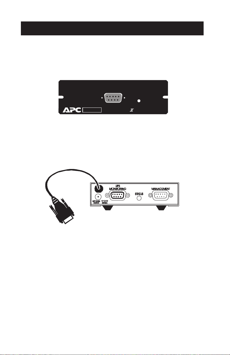
2.1 The Call-UPS II Panel
The SmartSlot Call-UPS II panel contains the management port and the
status indicator. See the figure below.
Management Port
Status
Smart SlotSmart Slot
AP9608 Call-UPS Remote Mgt Device
The external Call-UPS II rear panel contains the management port, status
indicator,
UPS monitoring port, and optional power jack. See the figure
below.
2.2 Management Port
The Call-UPS II management port is used for configuring Call-UPS II and
for remote management and paging by modem. For specifications, see
Sec. 6.1.
2.3 UPS Monitoring Port [External Version]
The UPS monitoring connector duplicates the signals from the UPS so
that the normal computer-tofor use with
APC software and interface kits only.
2
UPS connection is maintained. This port is
Page 7

2.4 UPS Cable [External Version]
Use this cable to connect Call-UPS II to an APC Smart-UPS, Matrix-UPS,
Symmetra Power Array or other
APC smart device (Share-UPS or Triple
Chassis, for example).
2.5 Power Port [External Version]
The external version of Call-UPS II has a power port for an optional
power adapter. This adapter is not needed in most situations. Callnormally receives power from the UPS through the UPS connection cable,
giving Call-
UPS II protection from poor power conditions. After UPS
shutdown for low-battery condition, Call-UPS II will still draw power
from the
ity of the
UPS for a time determined by the size of the load and the capac-
UPS. However, Call-UPS II stops drawing power from the UPS
before the battery is completely drained.
To determine whether a power connector will be useful, refer to the two
paragraphs that follow. You can obtain a power adapter by contacting
APC technical support at one of the numbers given on the back cover of
this manual. The
APC part number for the power adapter is AP9505.
With Smart-UPS
The optional power adapter is required for some older Smart-UPS models
that do not supply power to CallSmart-
UPS supplies power to Call-UPS II, refer to the Smart-UPS user
UPS II. To determine whether your
manual. Plug the adapter into a wall receptacle if you want remote turnon and turn-off capability; otherwise, plug it into a Smart
(Smart-
UPS models 250, 370, and 400 cannot be turned on or off by
-UPS receptacle.
remote connection; for these models plug the adapter into a Smartreceptacle.)
UPS II
UPS
With Matrix-UPS
You will need the optional power adapter for use with Matrix- UPS only
if you want remote turn-on capability. Matrixremotely by Calllose power. The
the
UPS Control menu of Call- UPS II ) without causing Call-UPS II to lose
UPS II, but, without the adapter, Call-UPS II will then
UPS will execute a Graceful Reboot command (item 5 on
UPS can be turned off
power. Plug the power adapter into a wall receptacle if you want remote
turn-on and turn-off capability. Otherwise, plug it into a Matrix-
UPS
receptacle.
3
Page 8

2.6 Status Indicator
The status indicator shows the following conditions.
STATU S LED IN DIC ATI ON
Off Call-UPS
On Continuously Call-UPS II is on with no user logged in.
Single short flashes User is logged in or logging in.
Double short flashes Lockout is in progress.
Rapid flashes Call-UPS II failed its power on self-test.
II
is off.
4
Page 9

3 Installation and Setup
3.1 Handling
Call-UPS II is sensitive to electrostatic discharge. It is shipped in a con-
ductive bag to help dissipate damaging static charges. Leave the product
in the bag until ready to install. Handle CallDo not touch the printed circuit board or other components.
3.2 Receiving Inspection
Once the Call-UPS II has been removed from its shipping container,
inspect it for damage that may have occurred while in transit. Notify
the carrier and place of purchase immediately if any damage is found.
The packing materials are recyclable and should be disposed of properly.
Please complete and return the enclosed warranty card.
Call-
UPS II is shipped with a null modem cable ( APC part number 940-
0103).
3.3 Installation
Before installing Call-UPS II, install your UPS. Then refer to the appro-
priate section that follows.
UPS II by the end plate only.
SmartSlot
If you are using a SmartSlot Call-UPS II with other SmartSlot devices,
refer to the appendix, “Multiple SmartSlot Installation” on pages 42 –43 .
While it is not possible to install the Calldamage the unit in the attempt to do so. Note the proper orientation of the
Call-
UPS II shown in the figure that follows. The sides of the printed cir-
cuit board align with the locating slots in the sides of the SmartSlot. In a
UPS, the SmartSlot may be oriented horizontally or vertically.
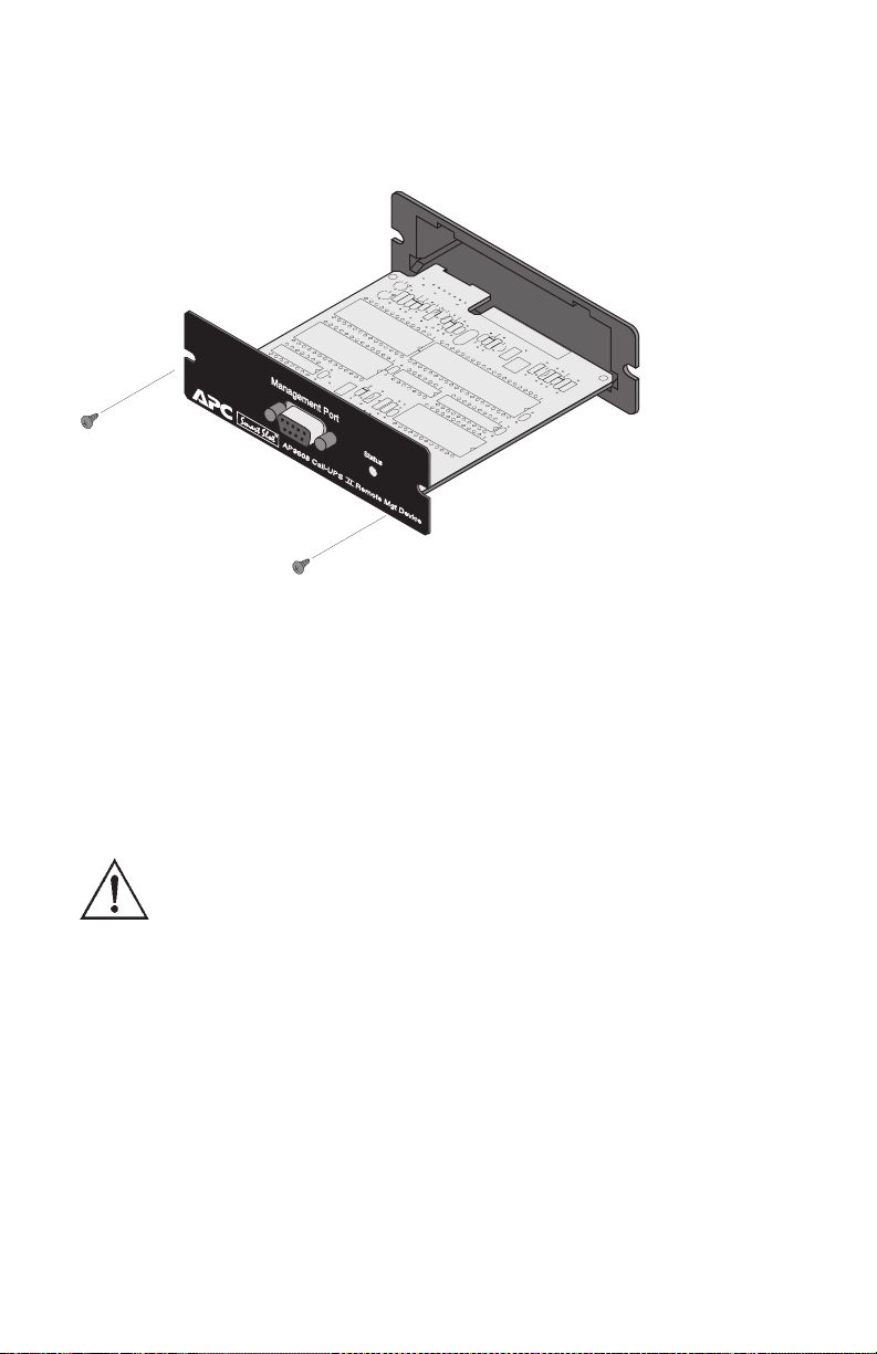
Use the following procedure to install the Call-
1 Shut down the protected loads and turn off the UPS.
2 Use a #2 Phillips head screwdriver to remove the two screws re-
taining the cover. Keep the screws handy for step 4 below. Retain
the cover for future use.
3 Orient the Call-
Slide the Callthe Call-
UPS II to fit in the SmartSlot as shown below.
UPS II all the way into the SmartSlot. The panel of
UPS II should be flush with the front face of the slot.
UPS II upside down, you can
UPS II:
5
Page 10
4 Secure the Call5 Turn on the
UPS II with the screws removed in step 2.
UPS and the protected equipment.
External Version
It is not necessary to turn off the the UPS or its load before connecting or
disconnecting the external Callcause the
UPS to beep, or, if the UPS is powered off, to power on. This is
UPS II. When connected, Call-UPS II may
normal.
Use only
of Call-
APC-supplied cables to connect the external version
UPS II to the UPS. Do not connect to any Call-UPS II port
except as specified in these instructions. Connections using a
cable or any other manufacturer may cause damage to or
improper operation of Call-
UPS II, the UPS, or the computer.
If a device such as a server or workstation is currently using the communi-
cations port on the back of the UPS, disconnect it now according to the
UPS connection instructions. Connect that device securely to the UPS
Monitoring Port on Call-UPS II. See Sec. 2.5 to determine if the optional
power adapter is required.
3.4 Confirm Operation
Observe the status indicator on Call-UPS II. After a moment it should
be on continuously. If the indicator flashes rapidly, Callits power-on self-test. See Chapter 5.
6
UPS II has failed
Page 11

3.5 Configure Call-UPS II
Call-UPS II requires on-site configuration before remote operation. You
will be able to change any of the settings later by the remote connection.
Follow these steps to configure Call-
• Communication parameters
• Password protection
• Time and date
• Paging (optional)
• Dial-back security (optional)
• Event logging (optional)
Initial Logging On
Connect DTE equipment (a dumb terminal or a computer running terminal emulation software) to the Management Port of Callsupplied null modem cable. It may be necessary to use an adapter (not
supplied) to connect the
DTE equipment to the null modem cable.
UPS II for:
UPS II using the
Set the communication parameters of the DTE equipment to
second, 8 data bits, no parity, and 1 stop bit (
With Call-
UPS II running (Status Indicator on steady), press CTRL + P
9600, 8, N, 1).
9600 bits per
(press and hold the CTRL key while pressing the P key). At the prompt:
Enter Password>
Type in APC and press ENTER.
Note: “
APC” is the factory default password for Call-UPS II. If the
default has been changed through previous configuration,
enter the changed password. Callcase sensitive. Enter
APC in upper case.
On correct entry of the password, Call-
UPS II communication is
UPS II displays the following
information:
---------------------- SMART-UPS 700 --------------------
Call-UPS II by American Power Conversion Corp
(c) Copyright 1994,95,97 All Rights Reserved
Site ID: 12345678
Location: Physical Location of This UPS
Press Any Key To Continue...
7
Page 12

Note the top line, which displays the model number of the
currently connected . Site
ID and Location are user configuration items.
UPS that is
The display shows the factory defaults.
Press any key to bring up the Main menu:
---------------------- MAIN MENU ------------------------
Date: Dec-16 '97 Time: 08:39:36
1- UPS Status
2- UPS Control
3- UPS Characteristics
4- Data/Event Logging
5- Call-UPS Settings
6- Paging Setup
7- Measure-UPS Info
?- Help
<ENTER> Display Menu
<ESC> End Session
>
Customize Settings
From the Main menu, you can go to the various menus by pressing the
number associated with each of them. Press 5, then
the Call-
UPS Settings menu. Set the date, time, password, location, and
baud rate from this menu. The baud rate should be set at
ENTER to bring up
9600. The other
menu items can be left alone for now. Note that any changes you make
are displayed when you return to the menu.
Then press
the Paging Setup menu, where you can change the Site
its default setting. If you will be using the paging capability of Call-
ESC to return to the Main menu. Type 6 and press ENTER for
ID number from
UPS
II, use this menu to enable and set up paging.
If you plan to use Calland press
ENTER for the Data/Event Logging menu. Proceed from there
UPS II for logging, go to the Main menu, type 4
to set up logging.
To change any of the changeable setting of the UPS and Call-UPS II, use
the other menus listed in the Main menu. For a full description of the entire menu scheme, see Section 4.
8
Page 13

Any changes to Callof the session. Changes are made when Call-
UPS II communication settings are held until the end
UPS II issues modem com-
mands at that time.
Connect to Modem
Call-UPS II requires a modem for remote UPS control and paging. If a
modem is used with Callit. Plugging the modem into the protected power output of the
UPS II, some thought must be given to powering
UPS will
keep the modem operating in bad power conditions, but remote turn-on
of the
UPS will not be possible since, when the UPS is off, the modem
is off. By plugging the modem into a wall socket, remote turn-on of the
UPS will work, but the modem will have to get by with unprotected
power. Also, it is possible in this situation to miss pages, since the
modem would be off in a power outage that Call-
UPS II tries to report by
paging.
A better option is to use a modem designed for portable computers that
draws power from the computer. Callproviding protected power whether the
a modem that draws power from Call-
UPS II will power such a modem,
UPS is on or off. Be careful to use
UPS II, not a battery.
The configuration is complete. Disconnect the management device from
Call-UPS II. Connect the Call-UPS II according to the appropriate system
connection diagram on the following page.
Note: Use a standard modem cable to make this connection. Do not
use the null modem cable supplied with Call-
UPS II.
9
Page 14
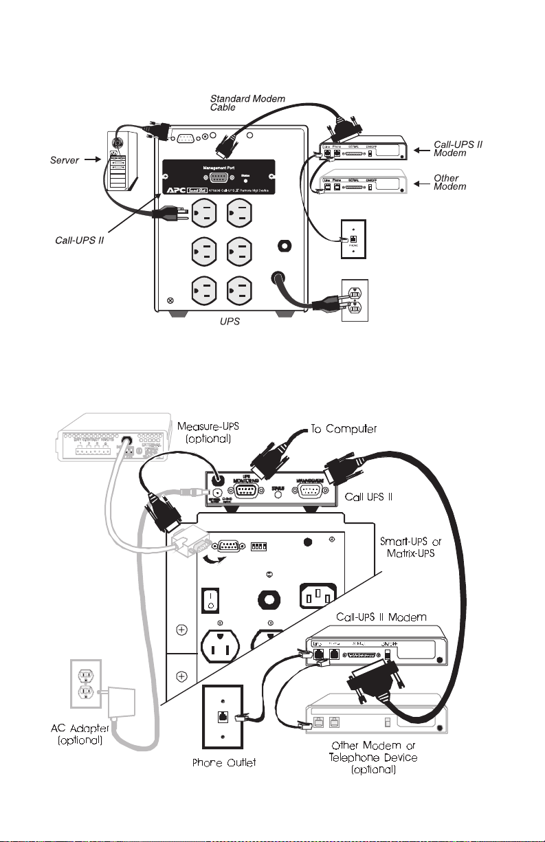
SmartSlot Configuration
External Configuration
10
Page 15

4 Operation
4-1 Logging On to Call-UPS II
For on-site logging on to Call-UPS II, see Section 3.5.
For remote logging on to Call-
the
UPS. After establishing communication, press CTRL + P. Call-UPS II
UPS II, connect via modem to the site of
prompts you for the password. Type in your password. (If you have not
changed the password, the default password is
APC.) The Opening
screen is diplayed. After pressing any key, the Main menu appears.
All Call-UPS II functions are available from the Main menu. To gain
access to one of the listed functions, type the associated number and
press
ENTER. To redraw the screen, press ENTER by itself.
Tip: Extensive online help is available throughout the menu
system. It is available whenever a “?” appears on a menu.
The “>” is the Call-
UPS II menu prompt. Call-UPS II uses the double
prompt “>>” to request a settable value. Some of these values can be
viewed by selecting them on the menu, pressing
through a list of possible settings and then pressing
SPACEBAR to cycle
ENTER to change the
setting to the current one listed.
Any time Call-UPS II responds to a command with the prompt “Are You
Sure?” Call-
UPS II requires confirmation of the command. Type YES in
uppercase letters at the prompt to confirm the command. Any other entry
aborts the command.
To return to the Main menu from another menu, press
ESC. Press ESC
from the Main menu screen to end the Call-UPS II session and hang up
the modem.
The paragraphs which follow give a description of the menus available in
the Main menu.
Note: Menu item 7 on the Main menu, Measure-
only if Call-
UPS II is used with a Measure-UPS environment
UPS Info, appears
monitor.
4.2 UPS Status [and Diagnostics]
The name and content of the first item on the Main menu varies according to the UPS being used. With a Smartitem is “
UPS Status.” When used with the Symmetra Power Array, the
UPS or a Matrix-UPS, the first
11
Page 16

first item is “UPS Status and Diagnostics.” Refer to the appropriate
sections and accompanying tables that follow.
With Smart-UPS and Matrix-UPS
Type 1, then ENTER at the Main menu to display the status of the connected UPS.
Note: This example is from a Matrix-
UPS 3000. Other models may
not show this exact information.
------------------ MATRIX 3000 STATUS ------------------Utility Line: 241.2 VAC Battery Info
UPS Output: 235.6 VAC ------------------
UPS Load: 000.0 % Voltage: 55.62 VDC
Run Time: 0185 min Capacity: 100.0 %
Load Power: 000.0 VA Smart Cells: 002
Load Current: 00.00 A Bad Cells: 000
UPS Temp: 019.8 C Batt Date: 02/23/97
Freq: 60.00 Hz Self Test: OK
Last Xfer: Test
<ESC>=Main menu>
The following table describes the items on the
Call-
Status: On-Line
UPS Status screen when
UPS II is used with Smart-UPS or Matrix-UPS.
12
Page 17

UPS STATUS (Sm art-UPS and Ma trix-UPS)
Ite m Description
Utility Line
UPS Output
UPS Load
Run Time
Load Power
Load Current
UPS Temp
Freq
Last Xfer
Voltage
Capacity
Utility line input, in volts A C RMS.
UPS output to the load, in volts A C RMS .
Connected load as a percentage of the rated capacity of the UPS.
Estimate of the total run time currently available from the
UPS, based on present load and battery, in minutes.
Amount of power being drawn by the load, in volt-amps (if
supported by the UPS).
Amount of current being drawn by the load, in amps (if
supported by the UPS).
Current temperature inside the UPS, in degrees Celsius.
Output frequency of the UPS, in hertz.
Reason for the last UPS transfer to battery. Possible results
are: Te st, Low Volta ge, Hi Voltage, Rate of Change, and
Notch/Spike.
Total voltage of the UPS batteries, in volts DC.
Battery charge as a percentage of capacity.
Smart Cells
Bad Cells
Batt Date
Self Test
Number of Smart Cell battery packs connected to the UPS
(only with Matrix-UPS).
Number of Smart Cells connected to the UPS that have gone
bad (only with Matrix-UPS).
Date of the last battery change.
Results of the last UPS self-test. Possible re sults are: OK,
None (not available), Unable to Test (inval id results due to
overload), and Battery Failed (due to insufficient capacity).
13
Page 18

The Status line at the bottom of the Status screen can display the follow-
UPS status conditions:
ing
• Runtime Calibration
• Waiting to Power Load
• Smart Boost
• Smart Trim
• On-Line
• On-Battery
• Low Battery
• Replace Battery
The following fault conditions display only when Calla Matrix-
UPS and a fault condition exists.
• Main Relay
• Batt Charger
• Bypass Relay
• Internal Temp
• In Bypass
• Sleeping – Delayed Wakeup
• Sleeping – Inverter Shutdown
• Forcing Graceful Shutdown
• Sleeping – Low Battery
• Shutdown Overload – Unable
to Transfer to Battery
• UPS Fault
UPS II is used with
• Iso Unit Fan
• Bypass Supply
• Voltage Select
• DC Imbalance
• Elec Unit Fan
If the
UPS is powered off during a status request, Call-UPS II responds
with the message:
UPS Powered OFF
14
Page 19

With Symmetra Power Array
Type 1, then ENTER at the Main menu to display the Status and Diagnostics screen of the connected Symmetra Power Array.
----------------------------- SYMMETRA STATUS ------------------------------IM Status: On & Ok Last Xfer: None
RIM Status: Off & Failed Last Self test: OK
------------------------------ INPUT/OUTPUT ---------------------------------
----------------------------- POWER MODULES ---------------------------------
------------------------------- BATTERIES -----------------------------------
System Status:On-Line
1- Main Frame Information
2- External Battery Frame Information for frame(s): 1, 2, 3, 6, 7
<ENTER>=Refresh, <ESC>=Main menu>, ?=Help>
Input: 246.0 V at 60.04 Hz Load Assuming No Redundancy: 000 %
Output: 000.0 V at 60.04 Hz Allowing for n+1 Redundancy: 000 %
Load Current: 00.0 A Capacity: 16.0 kVA
Installed: 05 Fault Tolerance: n+0
Bad: 00 Alarm if Under: n+2
Installed: 004 Voltage: 137.1 VDC Runtime: 0244 min.
Bad: 000 Capacity: 98.0 % Alarm if Under: 015 min.
Alarm if Over: 06.0 kVA
The following table describes the items on the
tics screen when Call-
UPS II is used with a Symmetra Power Array. The
UPS Status and Diagnos-
table continues on the next page.
UPS S TATUS AN D DI A GNO ST ICS ( Sym me tr a Po wer Ar ray )
Item Description
IM Status
RIM Status
Last Xfer
Last Self Test
Input
Output
Load Current
Status of the Intellige nce Module.
Status of the Redundant Intelligence Module.
Reason for the last UPS transfer to battery. Possible
results are: Test, Low Voltage, HiVoltage, Rate of
Change, and N otch/Spike.
Results of the last Sel f Test. Possible results are listed
in earlier Self Test Table in this section.
Utility line input, in volts AC RMS and in hertz.
UPS output to the load, in volts AC RMS and in hertz.
Amount of current being drawn by the load, in amps.
15
Page 20

UPS STATUS AN D DIAGNO S TIC S
(Symmetra Power Array, Co ntinued)
Item Description
Load Assuming No
Redundancy
Allowing For
n+[1] Redundancy
(Battery Po wer)
Capacity
(Load)Alarm
if Over
Installed
Bad
Fault T oler ance
Connected load as a percentage of the capacity of the
good battery modules, assuming a ll good m odules
are available for power.
Connected load as a percentage of the capacity of the
good battery modules, assuming one [two, no] good
module is reserved for redundancy. The value of
redundancy (n+0, n+1, n+2) is taken from the Alarm
if Under setting (see below).
Battery power available, in kilovolt-amps.
Load alarm threshold, in kilovolt-amps. If the load is
at or above this setting, an alarm sounds. Changeable
in the UPS Characteristics menu.
Number of power modules/batteries installed in the
Symmetra Power Array.
Number of power modules/batteries that have failed.
Redundancy of the Symmetra Power Array, given the
present load and battery capacity. A Fault Tolerance
of n+2, for example, means that two modules could
fail and there would be enough power for the load in
the event of utility line power outage.
(Fault Tolerance)
Alarm if Under
Voltage
(Battery Charge)
Capacity
Runtime
(Runtime)
Alarm if Under
16
Low redundancy ala rm. If the Fault Tolerance goes
below this setting, an alarm sounds. Changeable in
the UPS Characteristics menu.
Total voltage of the batteries, in volts DC.
Battery charge as a percentage of capacity.
Estimated runtime on-battery with the present load,
based on the latest Run Ti me Calibr ation (Sec. 4.3).
Runtime alarm threshold, in minutes. If the Runtime
reading falls below this setting, an alarm sounds.
Changeable in the UPS Characteristics menu.
Page 21

The System Status line at the bottom of the UPS Status and Diagnostics
screen can display the following Symmetra status conditions:
• Runtime Calibration
• Waiting to Power Load
• Smart Boost
• Smart Trim
• On-Line
• On-Battery
• Low Battery
• Replace Battery
• In Bypass
• Sleeping – Delayed Wakeup
• Sleeping – Inverter
Shutdown
• Forcing Graceful Shutdown
• Sleeping – Low Battery
Shutdown
• Overload – Unable
• Bad Power Module
• Intelligence Module is installed and failed
• Redundant Intelligence
Module is installed and
failed
• Bad Battery Module
• Load is above kVA alarm
threshold
• Redundancy has been lost
• Redundancy is below alarm
threshold
• Bypass is not in range (either
freq or voltage)
• Bypass contactor stuck in
bypass position
• Bypass Contactor stuck in
on-line position
• UPS in bypass due to internal
fault
• UPS in bypass due to overload
• System is in Maintenance
Bypass
• Input circuit breaker tripped
open
• System level fan failed
• The Redundant Intelligence
Module is in control
• IIC inter-module communications failed
• Turn on requested, override
required
• UPS will turn on automatically when conditions are met
• Runtime is below alarm
threshold
• # of batteries increased
• # of batteries decreased
• # of power modules increased
• # of power modules decreased
• Intelligence Module inserted
• Intelligence Module removed
• Redundant Intelligence Module inserted
• Redundant Intelligence Module removed
• # of External battery Cabinets
increased
• # of External Battery Cabinets
decreased
17
Page 22

If the UPS is powered off during a status request, Call-
UPS II responds
with the message:
UPS Powered OFF
In addition to providing general status information, the UPS Status and
Diagnostics screen serves as a menu for obtaining more detailed information on the Symmetra frames and external frames.
To go to the Main Frame screen, type 1 and press
ENTER. The following
display will appear.
Main Frame
+---------------+–--------------+
L1- | Power Module | None | -RIM
| No Module IIC | OK | -IM
+---------------+---------------+
L2- | Power Module | Battery |
|OK | OK |
+---------------+---------------+
L3- | Power Module | Battery |
|OK | OK |
+---------------+---------------+
L4- | Power Module | Battery |
|OK | OK |
+---------------+---------------+
L5- | Power Module | Battery |
| BAD | None |
+---------------+---------------+
<ENTER>=Refresh, <ESC>=Status Menu, ?=Help, or module
code for details>
The Main Frame screen is a map of the Symmetra array. The left column
displays the five levels of power module slots (
L1 to L5). The box at the
top of the right column displays the status of the Redundant Intelligence
Module (
(
IM) on the second line. The remainder of the right column displays the
RIM) on the first line and the status of the Intelligence Module
four levels of batteries. The power module and battery boxes display the
status of the corresponding power module or battery on the second line.
The Main Frame screen also serves as a menu for more detailed information on each of the power modules and the intelligence modules. By typing
L1 and pressing ENTER, for example, you can view a screen that dis-
plays information regarding Power Module
Intelligence Module, type
IM and press ENTER, and so on. Included in
L1. For information on the
this information are hardware and firmware version numbers and the
18
Page 23

module serial number, in addition to raw status readings. Normally you
will not need to go to these module status screens unless you need information for technical support. To return to the Main Frame screen, press
ESC.
For External Battery Frame(s) Information, type 2 and press
ENTER. The
last choice is available only when external battery frames are connected
to the Symmetra power array. These external battery frames are numbered and listed next to the menu item. (See earlier screen capture of the
UPS Status and Diagnostics screen.) The message prompts you to enter
the battery frame number. Type the number of one of the external battery
frames to go to a Battery Frame screen. An example follows.
Battery Frame
+---------------+–--------------+
| Battery | Battery |
|OK | OK |
+---------------+---------------+
| Battery | Battery |
| Failed | No frame IIC |
+---------------+---------------+
| Battery | Battery |
|OK | OK |
+---------------+---------------+
| Battery | Battery |
| None | OK |
+---------------+---------------+
| Battery | Battery |
| None | None |
+---------------+---------------+
| Battery | Battery |
| None | None |
+---------------+---------------+
Batteries possible: 12 F/W Rev: A01 Manuf. Date: 06/06/97
Batteries Installed: 07 H/W Rev: G98 S/N: W960123456789
ENTER=Refresh, ESC=Status menu, or enter frame number>
19
Page 24

4.3 UPS Control
For remote control of the connected UPS, go to the Main menu and type 2
and press
ENTER. Call-UPS II displays the Control menu.
--------------------- CONTROL MENU ----------------------
>
1- Turn UPS ON
2- Turn UPS OFF
3- UPS Self Test
4- Simulate Power Failure
5- Graceful Reboot
6- Graceful Turn OFF
7- Start Runtime Cal (Stop Runtime Cal)
8- Put UPS in Bypass (Return from Bypass)
?- Help
<ENTER> Display menu
<ESC> Return to Previous menu
Select from the menu items to perform the following:
UPS CONTR OL
Command Description
Turn UPS ON
Turn UPS OFF
Restores power to the load.
Cuts off power to the load immediately. T his does not
allow for graceful shutdown for operating systems that
require it.
UPS Self Test
Simulate Power
Failure
Graceful
Reboot
20
Starts a UPS self test and displays the results.
Puts the UPS on battery for a moment as if there were a
power failure.
Causes the UPS to cycle power to the a tt ached computer
to reboot it. Call-UPS II signals that the UPS is on
battery and that the battery is nearly exhausted. Graceful
Reboot uses the value set for Low Batte ry D uration. See
UPS Characteristics table, Sec. 4.4.
Page 25

UPS CONTROL (Continued)
Command Description
Causes the UPS to shut down. Call-UPS II immediately
Graceful Turn
OFF
Start(Stop)
Runtime
Calibration
signals that the UPS is on battery and that the battery is
nearly exhausted. Graceful Turn OFF uses the value set for
Low Battery Duration. See UPS Characteristics table in
Sec. 4.4.
Starts and stops runtime calibration on the UPS.
Calibration starts only if the UPS has a 100% battery
charge. If the UPS accepts the command to start runtime
calibration, Cal l-UPS II reports “Runtime Calib: OK.” If
the UPS does not accept the command, Call-UPS
reports “Runtime Calib: NO.” Runtime is displayed on the
UPS Status [and Dia gnos tics] Screen.
product s with serial numbers that begin with the letter
do not support runtime calibration.
II
Note: Smar t-UPS
W
Put UPS in
(Return from)
Bypass
UPS is powered off when UPS Control is selected from the Main
If the
menu, Call-
--------------------- CONTROL MENU ----------------------
<ENTER> Display menu
>
UPS II responds with an abbreviated control menu:
1- Turn UPS ON
2- Turn UPS OFF
?- Help
<ESC> Return to Previous menu
Type 1 to turn the
press
ENTER to re-display the full UPS Control menu.
For Matrix-UPS and Symmetra Power Array only
UPS in Bypass mode and returns the UPS from Bypass
mode.
UPS on, then press ESC to return to the Main menu or
. Puts the
21
Page 26

4.4 UPS Characteristics
UPS characteristics are set at the factory for normal operation and usually
do not need to be changed. However if a change is needed, select items
from the
operation of UPS monitoring software in use, so check the requirements
of the system before changing them. Default and optional values for these
settings vary from one UPS to another.
UPS Characteristics menu. New settings may conflict with the
Note: Smart-
UPS products with serial numbers beginning with
the letter W do not support reporting and setting
UPS
characteristics with Call-UPS II. In this case, item 3, UPS
Characteristics will not appear on the Main menu.
To display or change the characteristics of the
ENTER from the Main menu. The appearance of the UPS Characteristics
menu will vary according to the type of the connected
UPS, type 3 and press
UPS. Refer to the
appropriate sections and accompanying tables that follow.
With Smart-UPS and Matrix-UPS
Call-UPS II connected to a Smart-UPS or Matrix-UPS displays the follow-
ing UPS Characteristics menu:
------------------- UPS CHARACTERISTICS -----------------
UPS ID: UPS_IDEN
1- Output: 240 V
2- Output Freq Range: AUTO
3- Output Voltage Reporting base: Auto
4- If UPS fails and freq or voltage is out of
---------------------------------------------------------
---------------------------------------------------------
---------------------------------------------------------
<ENTER> Display Menu
<ESC> Return to Previous Menu
range: Go to Bypass
5- Low Battery Duration: 02 min.
6- Shutdown Delay: 020 sec.
7- Return Delay: 000 sec.
8- Return Battery Capacity: 00 %
9- Scheduled Self Test: every 14 Days
10- Alarm if runtime is less than: 000 min.
11- Alarm if load is greater than: 00.0 kVA
12- Alarm if redundancy is less than: n+2 (0=never)
13- Reset UPS to Default Settings
?- Help
22
>
Page 27

You can choose a numbered item to change its current setting. Type its
corresponding number and press
prompted to cycle through the settable values. Press
any change and return to the
ENTER. Press SPACEBAR when
ENTER to confirm
UPS Characteristics menu.
The following table gives a description of the settings on the UPS Characteristics menu. Those marked with a † are non-settable characteristics.
UPS CHARACTERISTICS (Smart- UPS and Matrix UPS)
Setting Description
†
Model
UPS Dip
Switches
UPS S/N
F/W Rev
†
†
†
UPS ID
Manuf. Date
Output
Battery Date
Low Transfer
Model name of the connected UPS.
Hexadecimal display of the UPS switch settings for those
UPSs that have them. Used by technical support.
Call-UPS II will not allow changes to U PS characteristics
if this value is other than 0.
Serial number of the UPS.
Revision number of the firmwa re in the UPS.
Identification of the UPS (not settable t hrough Cal l-UPS II).
†
Date of manufacture of the UPS.
Rated output voltage of the UPS. Settable for UPSs that
allow change of output voltage. You will be prompted to
select from the choices displayed.
Date of the last battery replacement (not settable through
Call-UPS II).
Lowest allowed utility line voltage before transfer to battery
operation. Consult your UPS and computer manuals for
proper setting.
transfer voltage
Note: Matrix-UPS does not allow setting low
.
Note:
High Transfer
High utility line voltage setting for transfer to battery
operation. Consult your UPS and computer manuals for
proper setting.
23
Page 28

UPS CHARACTERISTICS (Smart- UPS and Matrix UPS, Cont.)
Setting Description
Sensitivity of the UPS to power line fluctuation. Set this
value according to the type and magnitude of expected
fluctuation and the susceptibility of the load. Values range
Sensitivity
Shutdown
Delay
Return Delay
from high to low sensitivity. Use lower sensitivity settings
when running from a less stable power source, e.g., an
inexpensive fuel-powe red gen erator, when you have determined that the connected devices can handle the instability.
Time interval between issuance of a UPS turn off command
and actual shutdown of the load. Since the UPS notifies the
computer of the impending shutdown, Shutdown Delay
allows for graceful turn off.
Time interval after which the UPS turns on after restoration
of utility power. Use return delay to prevent branch circuit
overloads.
UPS Self Test
Audible Alarm
Low Battery
Duration
Return
Battery
Capacity
Reset UPS to
Default
Settings
Time intervals between UPS battery self-tests.
Function of the UPS audible alarm.
Time interval between low-battery warni ng and shutdown of
the UPS. Select from values between 2 and 10 minutes.
Battery capacity desired for UPS restart after a power
outage. Select from values between 0% and 90%. A t 0%,
the UPS will restart as soon as utility line power returns to
normal. With other settings, the UPS will charge the
batteries to the specifie d level pri or to restart.
Returns the UPS to its default state. Type
uppercase) and press
resetting. Any other entry stops resetting.
when prompted to confirm
ENT ER
YES
(all
24
Page 29

With Symmetra Power Array
Call-UPS II connected to a Symmetra Power Array displays the following
UPS Characteristics menu:
------------------------------ UPS CHARACTERISTICS ---------------------------
UPS ID: UPS_IDEN
1- Output: 240 V
2- Output Freq Range: 60/.1 Hz
3- Output Voltage Reporting Base: Auto
4- If UPS fails and freq or voltage is out of range: Go to Bypass
------------------------------------------------------------------------------5- Low Battery Duration: 02 min.
6- Shutdown Delay: 020 sec.
7- Return Delay: 000 sec.
8- Return battery Capacity: 10 %
9- Scheduled Self Test: every 14 days
-------------------------------------------------------------------------------
10- Alarm if runtime is less than: 015 min.
11- Alarm if load is greater than: 05.0 kVA
12- Alarm if redundancy is less than: n+1 (0=never)
-------------------------------------------------------------------------------
13- Reset UPS to Default Settings
<ENTER> Display menu
<ESC> Return to Previous menu
>
To change a setting, type the number of the menu item and press ENTER.
The following screen displays when you enter “9.”
NOTE: Changes May Conflict with monitoring Software
Press <SPACE> To See Next Entry, <ENTER> To Accept
UPS Self Test> 14 Days
The following table gives a description of the settings on the UPS Characteristics menu for Call-
UPS II connected to the Symmetra Power Array.
25
Page 30

UPS CHARACTERISTICS (Symmetra Pow er Array)
Setting Description
Output
Output Freq
Range
Output Voltage
Reporting base
If UPS fails …
Low Battery
Duration
Shutdown Delay
Return Delay
Output voltage of the UPS, in volts AC.
Output frequency range of the UPS, in hertz.
Desired output voltage setting. The default setting, Auto,
indicates that output voltage equals the nominal i nput
voltage. Other settings are 208 VAC and 240 VA C.
Instructs the UPS to go to bypass mode or to drop t he
load in the event the UPS fails and the frequency or
voltage is out of range of their settings (see 1 and 2 on
this menu).
Time interval between low-battery warning and
shutdown of the UPS. Select from values between 2 and
10 minutes.
Time interval between the issuance of a UPS turn off
command and actual shutdown of the load. Since the
UPS notifies the computer of the impending shutdown,
Shutdown Delay allows for gra ceful turn off.
Time interval after which the UPS turns on after
restoration of utility power. Use Return Delay to prevent
branch circuit overloads.
Return Battery
Capacity
Scheduled Self
Test
Alarm if …
Reset UPS to
Default
Settings
26
Battery capacity desired for UPS restart after a power
outage. Select from values between 0% and 90%. At
0%, the UPS will restart as soon as utility line power
returns to normal. With other settings, the UPS will
charge the batteries to the specified level prior to restart.
Ti me intervals between UPS battery self-tests
Three alarm thresholds. An alarm will sound if any of
the three alarm settings — calculated runtime, load, and
redundancy — is out of range. For a description of these
settings, see UPS Status and Diagnostics table, Sec. 4.2.
Returns the UPS to its default state. Type
uppercase) and press
resetting. A ny other e ntry stops resetting.
ENTER
when prompted to confi rm
YES
(all
Page 31

4.5 Data/Event Logging
To enable logging and to specify which data and events are included in
logging, select 4 from the Main menu. Select items from the Data/Event
Logging menu using the screen listing below.
--------------------- LOGGING MENU ---------------------1-Power Events: ON 3 - UPS Faults: ON
2-UPS Control: O N 4 - User Activity: O N
Date: Jul-27 ’97 Time: 15:05:35
---------------------------------------------------------
Jul-27 15:01:12 UPS Returned On Line
Jul-27 15:01:34 Shut Down Until Power Returns
Jul-27 15:01:38 Power Restored, Load Powered ON
--------------------------------------------------------6- List Event Groups
7- View Event Log
8- Reset Event Log
9- Log UPS Data to screen
10- Log Interval: 1 min
11- Data Format: Text
?- Help
<ENTER> Display menu
<ESC> Return to Previous menu
>
5- Measure-UPS: OFF
The following is a sample Call-
UPS II UPS data log, with Data Format set
to Text:
Jul-27 ’97 14:42:39
Line:117.8VAC Max:119.0VAC Min:117.1VAC Batt:27.67VDC
Freq:60.00Hz Temp:025.2C Load:017.6%
Jul-27 ’97 14:43:39
Line:119.0VAC Max:119.0VAC Min:117.8VAC Batt:27.67VDC
Freq:60.00Hz Temp:025.2C Load:017.6%
Jul-27 ’97 14:44:39
Line:119.0VAC Max:119.0VAC Min:117.8VAC Batt:27.67VDC
Freq:60.00Hz Temp:025.2C Load:018.7%
Jul-27 ’97 14:45:39
Line:118.4VAC Max:119.0VAC Min:117.8VAC Batt:27.67VDC
Freq:60.00Hz Temp:025.6C Load:018.7%
For a description of the items on the Data/Event Logging menu, refer to
the table that follows.
27
Page 32

DATA/ E VEN T LO GGI N G
Item Default Description
Power
Events
ON
UPS Control ON
UPS Faults ON
User
Activity
ON
Measure-UPS OFF
List Event
Groups
View Event
Log
Reset Event
Log
Displays a list of all reportable events, sorted into event
groups.
Displays the event log. Call-UPS II pauses after each page of
log information.
Clears the event log. Log information is kept in non-volatile
memory, so log items remain even when Call-UPS II is off.
Call-UPS II will log power events, such as utility
line failure and battery exhausted, when enabled.
Enter 0 when prompte d to disa ble, 1 to enable.
Call-UPS II will log control events, such as UPS
turned on and UPS in bypass, when enabled. Enter
0 to disable, 1 to enable.
Call-UPS II will log UPS faults, such as UPS is
overloaded, and internal temperature too high,
when enabled. Enter 0 to disable, 1 to enable.
Call-UPS II will log user activity, s uch as users
logging on and password changes, when enabled.
Enter 0 to disable, 1 to enable.
Call-UPS II will log Measure-UPS alarms, e.g.,
high temperature, low temperature, and contact
closure, when enabled. Ent er 0 to disable, 1 to
enable.
Log UPS Data
to Screen
Log
Interval
Data Format
28
Queries the UPS for operating data at preset intervals (see
next item) and displays this information on the screen.
Call-UPS II reports date, time, current line voltage, mini-mum
line voltage, ma ximum line voltage, battery voltage, line
frequency, internal UPS temperature, and UPS load.
Time interval at which Call-UPS II queries the UPS for log
data. The default is 1 minute. Set from 1 to 99 minutes
between queries, depending on how much data is needed.
Choose one of two log data output formats. Use text, the
default, if the dat a will be used in word processing programs.
Use the comma delimited format for im porti ng the data into
spreadsheets or databases.
Page 33

4.6 Call-UPS Settings
To see or change Call-UPS II settings, go to the main menu and type 5,
then press
---------------------CALL-UPS SETUP ---------------------
---------------------------------------------------------
---------------------------------------------------------
<ENTER> Display menu
>
ENTER. You will see the following display.
Model Number: AP9608 HW Rev: A 2
Serial Number: WA718570411 F/W Rev: K
Manuf. Date: 6/27/97
1- Set Date: Sep-28 ’97 7- Ansi Color: Off
2- Set Time: 10:38:06 8- Baud Rate: 9600
3- Set Password: ******** 9 - Answer Ring: 0
4- Dial Back: OFF 10-Answer Lockout: 0 min
5-Dial Back Str: DT5551212
6- Location: Physical Location of This UPS
11- UPS Present: ON
12- Reset Call-UPS to Default Settings
?- Help
<ESC> Return to Previous Menu
The top section of the CallCall-
UPS II device information which will be needed in case technical
UPS Setup menu displays the following
support is required:
• Model Number — the model number of Call-
UPS II
• H/W Rev — the revision of the Call-UPS II hardware
• Serial Number — the serial number of this Call-
F/W Rev — the revision number of the Call-UPS II firmware
•
• Manuf. Date — the date this Call-
The remaining two sections of the Callsettings of Call-
UPS II. For a description of these settings, see the table
UPS II was manufactured
UPS Setup menu list changeable
UPS II unit
that follows.
29
Page 34

CALL -UPS II SE TTINGS
Setting Default Description
Set Date
Set Time
Set
Password
Dial
Back
Dial
Back Str
Location
– Curre nt date in mm/dd/yy format.
–
APC
OFF
DT55512 12
Physical …
Current time in hh:m m:ss forma t. Call-UPS II uses
24-hour format.
From 0 to 8 alphanume ric chara cters. Use no
characters (press ent er when prom pted for the
password) for no password.
Dial Back Security feature. With Dial Back on,
Call-UPS II hangs up when called, and then calls the
number you set for the Dial Back String (see next).
Dial string used to implement dial-back security (see
preceding). Cal l-UPS II prefaces this string with t he
attention command, so do not include AT in the
string. Use industry standard dial strings of up to 20
alpha-numeric characters for the telephone number of
the modem to be called back. Use the vertical bar
(pipe) character (|) to start a new line in the string.
Make sure the remote modem is set to answer calls.
Description of the physical location of the UPS. Use
up to 40 alphanumeric characters. Call-UPS II does
not wordwrap, so use the vertical bar (pipe) character
(|) to start a new line. For example, “ACME Company|Any Town” will display: ACME Company
Any Town
30
Ansi
Color
Baud
Rate
OFF
960 0
Causes Call-UPS II to send ANSI standard color
display escape sequences when on.
Call-UPS II communication setting, i n bits per second.
Choose between 1200, 2400, 9600, and 19,200 bps.
Set to the highest supported bit rate of the DTE port
of the modem or other DCE equipment in use. Many
modems have DTE port rates that are higher than the
communication link rate in order to support data
compression. For example, ma ny 9600 baud modems
will support bit rates of 19,200 or higher at their DTE
ports. Consult your modem user manual.
Page 35

CALL -UPS II S E TT INGS ( C ont inued)
Setting Default Description
Number of rings before the Call-UPS II modem
answers a call. After each communication session, t he
modem SO register is set to this value. If the value is
Answer
Ri ng
Answer
Lockout
0
0 min
0 (the default), Call-UPS II wil l send “ATSO=0,” and
the modem will not answer calls. Set this value to 0
to use Call-UPS II for paging only. With Answer
Ring set to 0, Call-UPS II will not answer a stray call
and will always be available for paging. Values from
0 to 15 are accepted.
Answer Lockout time interval, for use of multiple
devices (like modems) on the same telephone line as
Call-UPS II. When set to a non-zero value, the
modem is prevented from accepting incoming calls
during the defined interval after a communication
session. To use Answer Lockout, m ake sure the
modem attached to Call-UPS II is the first device in
the telephone line chain (see figure at end of Sec.
3.5). When this feature is enabled, the next device
down the chain will get as many rings as it needs to
answer a call. Make sure that all othe r autom atic
answering devices on the line with Call-UPS II are se t
to answer in a greater number of rings than Call-UPS
II. Values from 0 to 99 minutes are accepted.
UPS
Present
Reset …
ON
States whether Call-UPS II is connected to a UPS.
Change the default setting (ON) if Call-UPS II is
connected only to Measure-UPS. This shortens the
menu structure and the polling sequence.
Resets Call-UPS II to factory defaults.
31
Page 36

4.7 Paging Setup
When used in conjunction with a modem that understands industry standard
AT commands, Call-UPS II can be set up to page an operator in case
of trouble, such as on-battery operation or problems with the UPS. To use
paging, choose item 6 on the Main menu menu to bring up the Paging
Setup menu. Select items from the Paging Setup menu, referring to the
screen listing and table later in this section.
Call-
UPS II reports the condition by showing a code on the pager’s dis-
play. Call-
Site
grammed by the user (see below). When a reportable condition occurs,
Calldem command string like this:
UPS II reports information in this format:
ID][space character][trouble code]
[Site
ID, Space Character, and Trouble Code are among the settings pro-
UPS II uses the modem to page an operator. Call-UPS II issues a mo-
The initial AT comes from Call-U PS II. Do not include it in the Dial
String. In this example, the Dial String is DT9,5551212@. DT instructs
the modem to dial in tone mode. The 9 and comma are only needed when
Call-
UPS II is used with a phone system that requires dialing 9 for an out-
side line. The comma adds a pause. The @ symbol at the end of the pager
phone number sets the modem to “wait for quiet answer” (five seconds
of silence) before entering the number to send to the pager. The
12345678
in the example comes from item number 8, Site ID, on the Call-UPS II
Paging Setup menu. Call-UPS II then issues the Space Character and
Trouble Code shown near the end of the example. For this example, the
pager would show:
12345678 1
Call-UPS II also issues the semicolon at the end of the modem command.
This sends the modem back into command state.
32
Page 37

----------------------- PAGING SETUP -----------------------1- Paging: ON
2- Dial String 1: DT9,5551212@
3- Dial String 2: DT9,5551212@
4- Repeat 1: 1 8- Site ID: 12345678
5- Repeat 2: 1 9- Space Char: *
6- Page Interval: 1 min 10- Dial Speed: Slow
7- Message Delay: 15 sec 11- End String:
--- EVENT ------ NUM: 1 2 CODE -- EVENT--NUM: 1 2 CODE
12- UPS ON-BATTERY Y N 0 20- ZONE 1 Y N 8
13- ON & LOW BATTER Y N 1 21- ZONE 2 Y N 9
14- UPS SHUT DOWN Y N 2 22- ZONE 3 Y N 10
15- UPS ON-LINE Y N 3 23- ZONE 4 Y N 11
16- REPLACE BATTERY Y N 4 24- ZONES CLEARY N 12
17- UPS FAULT Y N 5 25- PROBE 1 Y N 13
18- LOST COM W/ UPS Y N 6 26- PROBE 2 Y N 14
19- BYPASS Y N 7 27- PROBES CLEARY N 15
-------------------------------------------------------------
?- Help
<ENTER> Display menu
<ESC> Return to Previous menu
>
PAGI NG SE TUP
Setting De fa ult Description
Paging
Dial
String 1
Dail
String 2
Repeat 1
Repeat 2
OFF
DT9,
5551212@
DT9,
5551212@
1
1
To e nable paging, enter 1 when prompted. Enter 0 to
disable.
Dial string for the pager (the first pager if two are
used). Use standard modem comm ands such as:
DP — dial in pulse mode; DT — dial in tone mode
W — wait for second dial tone; , (Comma) — pause
(typically for 2 seconds); @ — wait for a quiet
answer (5 seconds of silence)
Dial string for a second pager number.
Number of times, from 0–4, that the page for the first
pager number is repeated. Call-UPS II cycles through
Repeat 1, Repeat 2, and Page Interval for each reportable event. Events are buffered and p rioritized during
paging to keep the operator updated with the best
information.
Note: pagi ng is also controlled on an
event basis (see later chart). Set Re peat t o 0 to disable a pager without having to disable all the events.
Same as Repeat 1, for pager a ssoc iated with Dial
String 2.
33
Page 38

PAG ING SETUP (Continued)
Setting Default Description
Time between paging cycles. This timeout occurs
after both pagers have been paged. After the
Page
Interval
Message
Delay
Site ID
1 min
15 sec
12345678
timeout, paging continues with the next pager
number that still has re peats as set above. Valid
entries are 0 to 10 minutes. With P ag e Interval set to
0, Call-UPS II repeats pages without delay.
Amount of time after on-battery operation that CallUPS II waits before initiating paging. This feature
prevents paging during brief power disturbances.
Select from the list of times, 15 through 120
seconds.
Identification number for the connected UPS, to be
reported during paging. Enter a unique and meaningful number of up to eight numeric (0–9) characters.
Keep in mind the length of the pager display.
Space
Character
Dial
Speed
End
String
*
Slow
Space character suitable for the pager. Select from
@, #, and none. This appears on the pager as a
space separating the Site ID from the trouble code.
Select from slow, medium, and fast dial speeds.
Unless dialing speed is needed, use t he defa ult, slow
dialing. Faster dial speeds may be incompatible with
some pagers and other t elephone e quipment.
Character(s) appended to the end of the Dial String.
Use an End String if the paging service has a menu
for reviewing and le aving mess ages. Call-UPS
appends a final semicolon (;) after the End String in
order to hang up the modem and return it to command mode.
II
The remaining fields in the Paging Setup menu define the events that
trigger a page, the pager(s) that will be paged when the event occurs, and
the code that will be displayed on the pager. Each event type can be set so
that either, both, or neither of the pagers will be paged for that event. The
defaults are “Y” (
ON) for the first pager, and “N” (OFF) for the second.
Event codes from 0 to 15 can be assigned to each type. The following
table describes triggering events and the default setting for each. A default of
“
Y N 5,” for example, means that the associated event in the first column
34
Page 39

will page the first pager but not the second, and that the first pager will
show a “5” after the Site
ID when it receives the page.
Note: The default code numbers defined by the Paging Setup menu
varies widely according to the type of
UPS. Measure-UPS,
zone, and probe alarms apply only if those devices are
present, even though they appear on the menu.
PAG ING SE TUP (E VENT S)
Event Description
UPS
ON-BATTERY
AC-FAIL/
LOW BATTERY
UPS
SHUT DOWN
UPS ON-LINE
REPLACE BATTERY
UPS FAULT
MEASURE-UPS
ALARM
MEASURE-UPS ALL
CLEAR
ZONE [n]
ZONES CLEAR
UPS is operating on battery power because of utility
line problems. T he Messa ge Delay setting (see earlier
Paging Setup menu ta ble) has been exceeded.
Utility power has failed, and the UPS battery is nearly
exhausted.
UPS has been shut down by command or low-battery
condition.
UPS has returned to online operation (after an on-
battery, low-battery, or shutdown condition).
UPS has issued a Replace Battery alarm.
UPS has detected an internal fault.
Measure-UPS environment monitor associated with the
connected UPS has issued an alarm.
All alarms from Measure-UPS have been cleared.
Zone monitor (1–4) has detected a condition that
exceeds preset zone monitor limits. For use with
Measure-UPS only.
Conditions triggering earlier Zone alarms have been
cleared.
PROBE [n]
PROBES CLEAR
Probe monitor (1–2) has detected a temperature or
humidity condition that exceeds preset probe limits.
For use with Measure-UPS only.
Conditions triggering earlier Probe alarms have been
cleared.
35
Page 40

4.8 Measure-UPS Info
Note: The Measure-UPS Info Main menu item appears only when
Call-
UPS II is used in conjunction with a Measure-UPS
environment monitor.
Type 7, then press
ENTER at the main menu to display Measure-UPS
status, settings, and alarms:
------------------- MEASURE-UPS STATUS ------------------
TEMP Celsius): 26.67
Low Limit: 1- 18.10 5-
High Limit: 2- 23.97 6-
HUMIDITY (%RH): 036.9
Low Limit: 3- 040.3 7-
High Limit: 4- 070.0 8-
F/W Rev: 4Gx
------------------ CURRENT ALARMS --------------------
<ESC>=Main Menu>
PROBE 1 PROBE 2
Hi Temp
Lo RH
The fields on this screen display Measure-UPS readings for each connected probe, settable alarm limits for each probe, and any current
alarms. To make changes to the alarm settings, type the number of the
menu item (1–8). If you want to change the low humidity limit for the
Measurethrough the available choices by pressing
make the selection and return to the Measureare finished making changes, press
UPS Probe 1, for example, you can type 3 and press enter. Scroll
SPACEBAR. Press ENTER to
UPS Info screen. When you
ESC to return to the Main menu. The
following table describes the status items and lists the choices for the
settable alarm limits.
36
Page 41

ME ASU RE -UPS INFO
Item Description
TEMP
Lo Limit
(Temp)
Hi Limit
(Temp)
HUMIDITY
Lo Limit
(Humidity)
Hi Limit
(Humidity)
F/W
Current Alarms
Current ambient temperature of each attached probe, in
degrees Celsius.
Setting for the low temperature Measure-UPS alarm.
Choose from 9.94 (the default), 14.02, 18.10, and 4.08
degrees Celsius.
Setting for the high temperature Measure-UPS alarm.
Choose from 32.13 (the default), 4 5.90, 54.06, and
23.97 degrees Celsius.
Current percentage of relative humidity of each probe.
Setting for the low humidity Measure-UPS alarm.
Choose from 20.1 (the default), 30.2 , 40.3, and 10.0
percent relative humidity.
Setting for the high humidity Measure-UPS alarm.
Choose from 80.0 (the default), 84.5 , 90.1, and 70.0
percent relative humidity.
Firmware revision number of Measure-UPS.
Status display of current Measure-UPS alarms, which
can include Lo Temp, Hig h Temp, Lo RH, Hi RH, and
the four contact closures. The earlier sample screen
shows Hi Te mp and Lo RH because the reported values
for these items exceed their respective alarm limits.
Press ENTER at the > prompt on the Measure-UPS screen to display fresh
readings.
37
Page 42

5 Problem Resolution
5.1 Troubleshooting Chart
TROUBLESHOOTING
Problem Possible Cause Solution
Power light flashes
rapidly when unit
is first turned on.
Remote modem
wi ll no t an s wer.
Cannot log in
locally to configure Call-UPS
II.
Internal problem with
Call-UPS
Call-UPS
Answer Ring set to 0.
Answer Lockout in
progress.
Remote modem plugged
into UPS that has been
turned off.
Modem did not receive
setup string from CallUPS
Call-UPS
back.
No @ symbol at the end
of the dial string.
II.
II.
Setup item
II
is dialing
II
Disconnect Call-UPS
the UPS momentarily, t hen
reconnect.
Set Answer Ring to value other
than 0 (ee Sec. 4.6).
Call back after Answer Lockout
interval has expired.
Plug remote modem into a wall
socket or use modem powered
by Call-UPS
Turn modem on before plugging
in Call-UPS
Press
in progress or type
press
echo this message, so typing
will be “blind.”
Add an @ sy mbol at the end of
the dial strings in the Paging
Setup Menu. Many paging
controllers need additional time
to establish a connection.
II.
; check the cables.
II
to bypass the dialback
ESC
. Call-UP S
ENT ER
from
II
connect
will not
II
and
Pages are not
getting through.
Not enough time
between repeats, or not
enough repeats.
Call-UPS
too quickly for the
paging equipment.
Space character cancels
sending the page.
is dialing
II
Add to the values in the Repeat
1, Repeat 2, and Paging Tim er
settings in Paging Setup.
Set Dial Speed in Paging Setup
to a lower value.
Set Space Character in Paging
Setup to none.
Page 43

The troubleshooting chart covers many of the problems that might arise
with Call-
UPS II. If you have a problem with Call-UPS II , refer to this
chart first. There may be a simple solution you are overlooking.
5.2 If Problems Persist
For problems not covered in the earlier troubleshooting chart, or if the
problem persists, follow this procedure:
1 Note the serial number and date of purchase of the Call-
Contact Customer Service at the phone number or address on the
back cover of this manual.
2 Be prepared to provide a description of the problem. A technician
will help solve the problem over the phone, if possible, or will
give you a Return Material Authorization (
3 If the Call-
UPS II is under warranty, repairs are free of charge. If
RMA) number.
the warranty has expired there will be a nominal charge for repair.
4 Pack the Call-
UPS II carefully to avoid damage in transit. Damage
sustained in transit is not covered under the warranty. Enclose a
letter in the package with your name, address,
RMA number, a
copy of the sales receipt, daytime phone number, and check (if
necessary).
5 Clearly mark the
RMA number on the outside of the shipping
carton. The factory will not accept any materials without this
marking.
6 Return the Call-
UPS II by insured, prepaid carrier to the address
on the cover of this manual.
UPS II.
39
Page 44

6 Specifications
6.1 Management Port
The management port is a standard 9-pin RS-232 serial communications
port. The port is configured as data terminal equipment (
handshaking, and supports bit rates of
1200, 2400, 9600 , and 19,200 bits
per second. The data format is 8 data bits, 1 start bit, 1 stop bit, and no
parity. The pinout of the management port is listed below.
MANAGE MENT P ORT P I NOUT
Pin Function
1 Unus ed
2 Re ceive data inpute
3 Transmit data output
4 RS-232 high
5 Ground
DTE) with no
40
6 Unus ed
7 Re quest to send output
8 Clear to send input
9 Unus ed
Page 45

6.2 Product Specifications
Electrical
Current Draw
(Normal Operation):
External 45 mAdc typical
Physical
External 1.33 × 4.25 × 4.5 in. (3.4 × 10.8 × 11.4 cm)
Size (H × W × D):
SS 1.5
External 0.89 lb (0.40 kg)
Weight :
SS 0. 27 lb (0.123 kg)
External 1.5 lb (0.68 kg)
Shipping Weight :
SS 0.8 lb (0.363 kg)
4.0 × 4.0 in. (3.8 × 10.2 × 10.2 cm)
×
En vi ronmenta l
Storage Elevation: Up to 50,000 ft (15,000 m) above MSL
Storage Relative Humidity: 0 to 95%, non-condensing
Storage Temperature : +4 to +122° F (-15 to +70° C)
Operating Elevation: Up to 10,000 ft (3,000 m) above MSL
Operating Relative Humidity: 0 to 95%, non-condensing
Operating Tempe rature: +32 to +113 F (0 to +45° C)
Ap proval s
EMC Verification: FCC/DO C Class B, EN50022, EN50082-1
41
Page 46

Appendix: Multiple SmartSlot Installation
If your UPS configuration uses more than one SmartSlot device, you
must install them in the correct order for them to work together properly.
A SmartSlot device with higher priority is to be placed in the SmartSlot
labeled with the higher number. Refer to the table that follows.
DEVICE PART # PRIORIT Y POSITIO N
PowerNet SNMP
Adapter
Call-UPS
II
Remote UPS
Management Device
AP9605 Highest Highest-numbered slot.
Second-highest-numbered
slot (highest if no PowerNet
SNMP Adapter is present).
AP9608
Second
Highest
Any slot numbered lower
Relay I/O Module AP9610 Medi um
than PowerNet SNMP
Adapter & Call-UPS
II
and
higher than Measure-UPS.
Any slot numbered lower
Interface Expander AP9607 Medium
than PowerNet SNMP
Adapter & Call-UPS
II
and
higher than Measure-UPS.
Measure-UPS AP9612TH Lowest L owest numbered slot.
Triple Chassis
To install SmartSlot devices in the APC Triple Chassis (AP9604), note
that the slots are numbered on the rear panel. The following figure shows
the rear panel of the Triple Chassis with the PowerNet
installed in slot #3, Call-
UPS II in slot #2 and Measure-UPS II in slot #1.
SNMP Adapter
42
To UPS
Power
24 VDC
–+–
Status
1
Sensor Zones
1 2 3 4
GND
Smart SlotSmart Slot
AP9612 Measure-UPS™
Probes
1 2
2
Management Port
AP9608 Call-UPS Remote Mgt Device
Smart SlotSmart Slot
3
Link - RX/TX
Status
Status
AP9605 PowerNet™ SNMP Adapter™
Smart SlotSmart Slot
Reset
Monitoring Port
Page 47

Symmetra Power Array
For installation of multiple SmartSlot devices in the Symmetra Power
Array, refer to the numbering in the figure that follows. Note that the
PowerNet
SNMP Adapter is installed in slot #4, Call-UPS II in #3, no
device in #2, and Measure-UPS in #1.
If you are using an external SmartSlot housing (Expansion Chassis or
Triple Chassis) in conjunction with a Symmetra Power Array, install the
devices with higher priority in the external slot(s). Refer to the earlier
Triple Chassis section, if applicable.
4 123
Battery Communications
Computer
Display
Comm.1 Comm. 2
Interface
Comm.
Reset
Status
Link - RX/TX
AP9605 PowerNet™ SNMP Adapter™
Slot
Smart SlotSmart
Status
AP9608 Call-UPS Remote Mgt DeviceAP9608 Call-UPS Remote Mgt Device
Management Port
Slot
Smart SlotSmart
Probes
1 2
1 2 3 4
Sensor Zones
GND
AP9612 Measure-UPS™
Slot
Smart SlotSmart
Daisy Chains
If you have increased your SmartSlot capacity by daisy-chaining
Expansion Chassis or Triple Chassis, install the PowerNet
SNMP
Adapter and Call-UPS II in the highest-numbered and second-highest-
numbered slots, respectively, of the chassis installed farthest from the
UPS.
Smart-UPS and Matrix-UPS
If your APC UPS has only one SmartSlot, install the low-priority devices
in the
UPS SmartSlot and use an external SmartSlot housing (Expansion
Chassis or Triple Chassis) for the device(s) with higher priority. Refer to
the earlier Triple Chassis section, if applicable.
43
Page 48

Page 49

Page 50

Page 51

Limited Warranty
American Power Conversion (APC) warrants its products to be free from defects in
materials and workmanship for a period of two years from the date of purchase. Its
obligation under this warranty is limited to repairing or replacing, at its own sole option,
any such defective products. To obtain service under warranty you must obtain a Returned
Material Authorization (RMA) number from APC or an APC service center. Products
must be returned to APC or an APC service center with transportation charges prepaid
and must be accompanied by a brief description of the problem encountered and proof
of date and place of purchase. This warranty does not apply to equipment which has
been damaged by accident, negligence, or misapplication or has been altered or modified
in any way. This warranty applies only to the original purchaser who must have properly
registered the product within 10 days of purchase.
EXCEPT AS PROVIDED HEREIN, AMERICAN POWER CONVERSION MAKES
NO WARRANTIES, EXPRESS OR IMPLIED, INCLUDING WARRANTIES OF
MERCHANT ABILITY AND FITNESS FOR A PARTICULAR PURPOSE. Some states
do not permit limitation or exclusion of implied warranties; therefore, the aforesaid
limitation(s) or exclusion(s) may not apply to the purchaser.
EXCEPT AS PROVIDED ABOVE, IN NO EVENT WILL APC BE LIABLE FOR
DIRECT, INDIRECT , SPECIAL, INCIDENTAL, OR CONSEQUENTIAL DAMAGES
ARISING OUT OF THE USE OF THIS PRODUCT, EVEN IF ADVISED OF THE
POSSIBILITY OF SUCH DAMAGE. Specifically, APC is not liable for any costs,
such as lost profits or revenue, loss of equipment, loss of use of equipment, loss of
software, loss of data, costs of substitutes, claims by third parties, or otherwise. This
warranty gives you specific legal rights and you may also have other rights which vary
from state to state.
Life support policy
As a general policy, American Power Conversion (APC) does not recommend the use
of any of its products in life support applications where failure or malfunction of the
APC product can be reasonably expected to cause failure of the life support device or to
significantly affect its safety or effectiveness. APC does not recommend the use of any
of its products in direct patient care. APC will not knowingly sell its products for use
in such applications unless it receives in writing assurances satisfactory to APC that (a)
the risks of injury or damage have been minimized, (b) the customer assumes all such
risks, and (c) the liability of American Power Conversion is adequately protected under
the circumstances.
Examples of devices considered to be life support devices are neonatal oxygen analyzers,
nerve stimulators (whether used for anesthesia, pain relief, or other purposes),
autotransfusion devices, blood pumps, defibrillators, arrhythmia detectors and alarms,
pacemakers, hemodialysis systems, peritoneal dialysis systems, neonatal ventilator
incubators, ventilators for both adults and infants, anesthesia ventilators, and infusion
pumps as well as any other devices designated as “critical” by the U.S. FDA.
Hospital grade wiring devices and leakage current may be ordered as options on many
APC UPS systems. APC does not claim that units with this modification are certified or
listed as Hospital Grade by APC or any other organization. Therefore these units do not
meet the requirements for use in direct patient care.
Page 52

Toll free technical support:
Addresses:
United States and Canada
1-800-800-4272
Ireland
1-800-702000
U. K.
0800-132990
Areas without toll free numbers:
+1 401 789 5735 (USA) or
+353 91 702020 (Ireland)
American Power Conversion Corporation
132 Fairgrounds Road
P. O. Box 278
West Kingston, Rhode Island 02892
USA
American Power Conversion Corporation
( A . P. C . ) b . v.
Ballybritt Business Park
Galway
Ireland
www.apcc.com
Serial number:
Entire contents copyright © 1997 American Power Conversion.
All rights reserved; reproduction in whole or in part without permission is prohibited.
990-0122B Rev. 3 12/97
All trademarks are the property of their respective owners.
 Loading...