

Page 1

AIS 5000
10–100 kVA
400 V
Installation Manual
®
Page 2

Page 3

Contents
Safety ..................................................................... 1
IMPORTANT SAFETY INSTRUCTIONS
- SAVE THESE INSTRUCTIONS . . . . . . . . . . . . . . . . . . . . . . . . . . 1
IMPORTANT SAFETY INSTRUCTIONS
— SAVE THESE INSTRUCTIONS . . . . . . . . . . . . . . . . . . . . . . . . . 1
Symbols used in this manual . . . . . . . . . . . . . . . . . . . . . . . . . . . 1
User Safety . . . . . . . . . . . . . . . . . . . . . . . . . . . . . . . . . . . . . . . . 2
General Information ................................................3
About this manual . . . . . . . . . . . . . . . . . . . . . . . . . . . . . . . . . . 3
Site Requirements . . . . . . . . . . . . . . . . . . . . . . . . . . . . . . . . . . . 4
Receiving and inspecting the UPS . . . . . . . . . . . . . . . . . . . . . . . 4
Moving the equipment to site: . . . . . . . . . . . . . . . . . . . . . . . . . 5
Air Filter . . . . . . . . . . . . . . . . . . . . . . . . . . . . . . . . . . . . . . . . . . 6
Fitting the air filter . . . . . . . . . . . . . . . . . . . . . . . . . . . . . . . . . . 6
Air filter sizes . . . . . . . . . . . . . . . . . . . . . . . . . . . . . . . . . . . . . . 7
Enclosure dimensions and footprint . . . . . . . . . . . . . . . . . . . . . 8
External Connection ..............................................12
Connecting the UPS . . . . . . . . . . . . . . . . . . . . . . . . . . . . . . . . 12
External connection board . . . . . . . . . . . . . . . . . . . . . . . . . . . 12
Installing Conduit Boxes . . . . . . . . . . . . . . . . . . . . . . . . . . . . . 13
Access to Input/Output section . . . . . . . . . . . . . . . . . . . . . . . . 15
Connecting cables . . . . . . . . . . . . . . . . . . . . . . . . . . . . . . . . . . 17
Grounding . . . . . . . . . . . . . . . . . . . . . . . . . . . . . . . . . . . . . . . 20
Emergency Power Off (EPO) . . . . . . . . . . . . . . . . . . . . . . . . . . 21
Communication interface . . . . . . . . . . . . . . . . . . . . . . . . . . . . 21
Communication interface ports . . . . . . . . . . . . . . . . . . . . . . . . 22
Overview of Communication interface . . . . . . . . . . . . . . . . . . . 23
990-2440 AIS 5000 400V Installation Manual i
Page 4

10kVA 400V UPS . . . . . . . . . . . . . . . . . . . . . . . . . . . . . . . . . . 24
IS10KH . . . . . . . . . . . . . . . . . . . . . . . . . . . . . . . . . . . . . . . . . . 24
20kVA 400V UPS . . . . . . . . . . . . . . . . . . . . . . . . . . . . . . . . . . 28
IS20KH . . . . . . . . . . . . . . . . . . . . . . . . . . . . . . . . . . . . . . . . . . 28
30kVA 400V UPS . . . . . . . . . . . . . . . . . . . . . . . . . . . . . . . . . . 32
IS30KH . . . . . . . . . . . . . . . . . . . . . . . . . . . . . . . . . . . . . . . . . . 32
40kVA 400V UPS . . . . . . . . . . . . . . . . . . . . . . . . . . . . . . . . . . 36
IS40KH . . . . . . . . . . . . . . . . . . . . . . . . . . . . . . . . . . . . . . . . . . 36
60kVA 400V UPS . . . . . . . . . . . . . . . . . . . . . . . . . . . . . . . . . . 40
IS60KH . . . . . . . . . . . . . . . . . . . . . . . . . . . . . . . . . . . . . . . . . . 40
80kVA 400V UPS . . . . . . . . . . . . . . . . . . . . . . . . . . . . . . . . . . 44
IS80KH . . . . . . . . . . . . . . . . . . . . . . . . . . . . . . . . . . . . . . . . . . 44
100kVA 400V UPS . . . . . . . . . . . . . . . . . . . . . . . . . . . . . . . . . 48
IS100KH . . . . . . . . . . . . . . . . . . . . . . . . . . . . . . . . . . . . . . . . . 48
Options ................................................................ 52
IP32 Drip Shield . . . . . . . . . . . . . . . . . . . . . . . . . . . . . . . . . . . 53
Mounting the drip shield . . . . . . . . . . . . . . . . . . . . . . . . . . . . . 54
Drip shield sizes . . . . . . . . . . . . . . . . . . . . . . . . . . . . . . . . . . . . 55
Relay Board . . . . . . . . . . . . . . . . . . . . . . . . . . . . . . . . . . . . . . 56
Communication Cards . . . . . . . . . . . . . . . . . . . . . . . . . . . . . . . 58
Cards and slots . . . . . . . . . . . . . . . . . . . . . . . . . . . . . . . . . . . . 58
Programming and Set-Up ...................................... 59
Display . . . . . . . . . . . . . . . . . . . . . . . . . . . . . . . . . . . . . . . . . . 59
Display introduction . . . . . . . . . . . . . . . . . . . . . . . . . . . . . . . . 59
Display functions . . . . . . . . . . . . . . . . . . . . . . . . . . . . . . . . . . . 60
Display messages . . . . . . . . . . . . . . . . . . . . . . . . . . . . . . . . . . . 61
Programming the UPS . . . . . . . . . . . . . . . . . . . . . . . . . . . . . . . 62
User stack . . . . . . . . . . . . . . . . . . . . . . . . . . . . . . . . . . . . . . . . 62
Settings for redundant systems . . . . . . . . . . . . . . . . . . . . . . . . 67
Setting stack . . . . . . . . . . . . . . . . . . . . . . . . . . . . . . . . . . . . . . 69
ii AIS 5000 400V Installation Manual 990-2440
Page 5

Operation Modes . . . . . . . . . . . . . . . . . . . . . . . . . . . . . . . . . . 71
Operation mode descriptions: . . . . . . . . . . . . . . . . . . . . . . . . . 71
Normal to Bypass Operation . . . . . . . . . . . . . . . . . . . . . . . . . . 72
Bypass to Normal Operation . . . . . . . . . . . . . . . . . . . . . . . . . . 72
Normal to Manual Bypass Operation . . . . . . . . . . . . . . . . . . . . 73
Manual Bypass to Normal Operation
(including start up procedure) . . . . . . . . . . . . . . . . . . . . . . . . . 74
990-2440 AIS 5000 400V Installation Manual iii
Page 6

Page 7
Safety
o
IMPORTANT SAFETY INSTRUCTIONS
- SAVE THESE INSTRUCTIONS
IMPORTANT SAFETY INSTRUCTIONS — SAVE THESE INSTRUCTIONS
This manual contains important safety instructions for the AIS series that should be followed during
installation, operation, and maintenance. See the battery installation manual for battery-specific
instructions.
Symbols used in this manual
WARNING!
Risk of electric shock.
Caution
Note
See als
CAUTION!
Read this information to avoid equipment damage.
Indicates important information.
Indicates that more information is available on this subject in a different section of this
manual.
Indicates that more information is available on the same subject in a different manual.
Use a pallet jack or a forklift for components over 54 kg.
Two people to lift a component weighing between 18 – 32 kg.
990-2440 AIS 5000 400V Installation Manual 1
Page 8
User Safety
WARNING!
This UPS contains hazardous AC and DC voltages. Only qualified electricians
should connect the UPS, AC line and external batteries, and must be familiar with
batteries and battery installation.
Before installing, maintaining or servicing the UPS, shut off the UPS and
disconnect all sources of AC and DC power.
As the UPS has no built-in disconnection devices to switch off external AC and DC
input power, ensure that disconnection devices are available as separate parts in
connection with the installation!
AC and/or DC voltage will always involve a potential risk of AC voltage at UPS
output generated from either batteries or utility. To avoid equipment damage or
personal injury, always assume that there may be voltage at UPS output.
This system is equipped with an auto-start function. If activated, the system may
start without warning. Refer to the “Programming” section for information on deactivation.
The installer must provide each external disconnecting device for this UPS system
with labels with the following text:
“Isolate the Uninterruptible Power Supply (UPS) as instructed in this guide before
working on circuit”
Caution
WARNING!
TEST BEFORE YOU TOUCH!
To reduce the risk of fire or electric shocks, install the UPS and external batteries
in a temperature and humidity controlled indoor area, free of conductive
contaminants.
WARNING!
UPS batteries are high-current sources. Shorting battery terminals, DC terminals
or DC busbars can cause severe arcing, equipment damage and injury. A short
circuit can cause a battery to explode. Always wear protective clothing and eye
protection and use insulated tools when working on batteries.
CAUTION!
This unit contains components sensitive to electrostatic discharge (ESD). If you do not
follow the ESD procedures, you may cause severe damage to electronic components.
990-2440 AIS 5000 400V Installation Manual 2
Page 9

General Information
About this manual
This Installation Manual gives a detailed overview of the various functions of the APC UPS system
and contains information on how to install, connect, program and maintain the AIS 5000 UPS
system.
Further information on the AIS 5000 series is available on www.apc.com.
990-2440 AIS 5000 400V Installation Manual 3
Page 10
Site Requirements
Receiving and inspecting the UPS
Your AIS 5000 UPS system has been tested and inspected for quality assurance prior to shipment
from APC. To ensure that the UPS has not been damaged during transportation, carefully inspect both
the exterior and interior of the equipment immediately upon receipt as described in the Receiving and
Unpacking folder.
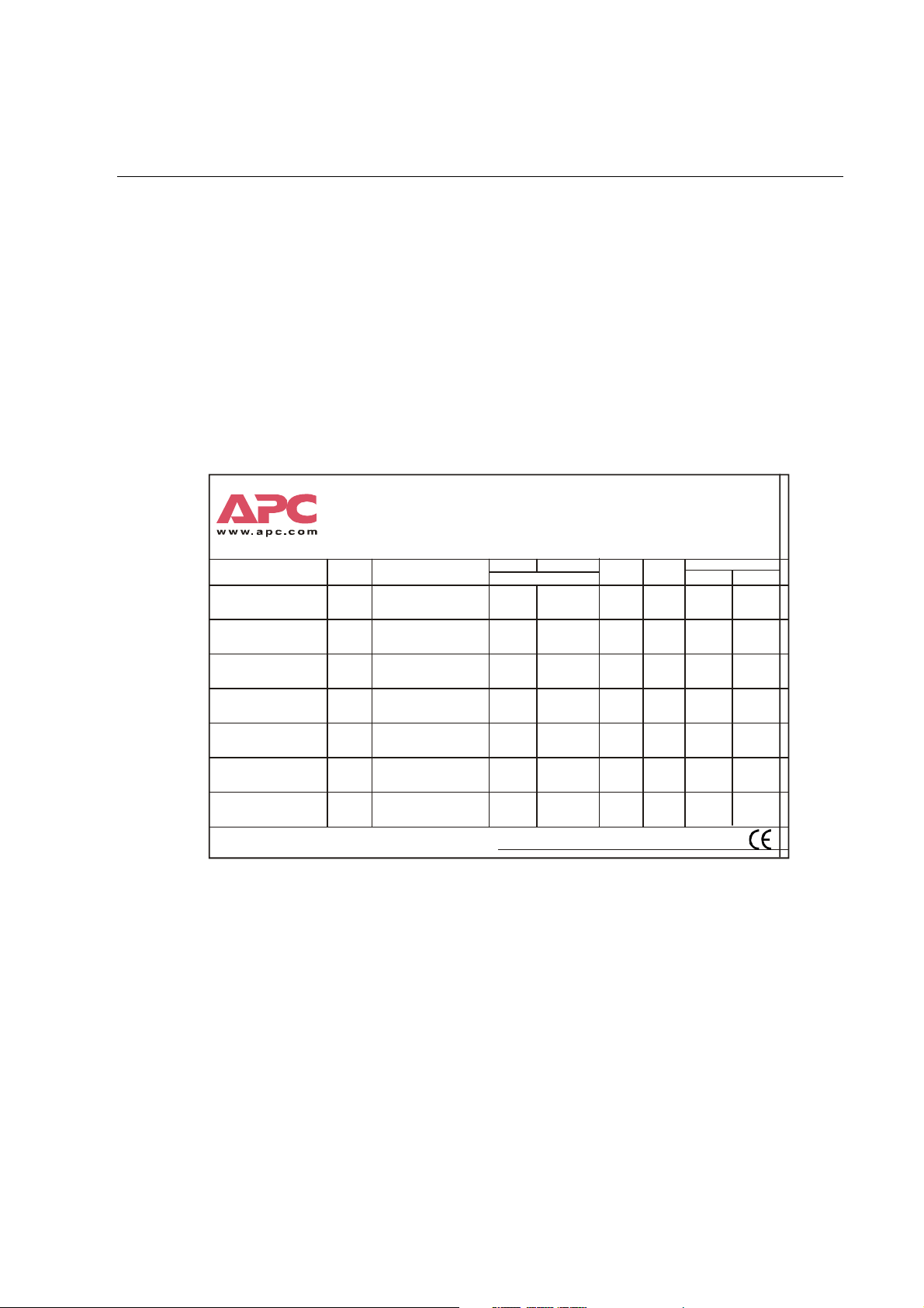
Type label. Copy type label data (serial number) to label copy below for easy identification of the
system. The type label is placed on the inside of the UPS front door.
Place label according to SKU no.
Hotline Support US /Canada/LAM
Hotline Support EMEA
World Wide Support numbers
SKU no.
IS10KH
IS20KH
IS30KH
IS40KH
IS60KH
IS80KH
IS100KH
400V for external bat teries
400V for external bat teries
400V for external bat teries
400V for external bat teries
400V for external bat teries
400V for external bat teries
400V for external bat teries
TEST PERSONNEL DATE AND SIGNATURE
+353 91 70 2000
Model
AIS 5000 10kVA
10kVA / 8kW
AIS 5000 20kVA
20kVA / 16kW
AIS 5000 30kVA
30kVA / 24kW
AIS 5000 40kVA
40kVA / 32kW
AIS 5000 60kVA
60kVA / 48kW
AIS 5000 80kVA
80kVA / 64kW
AIS 5000 100kVA
100kVA / 80kW
800 800 4APC
Www.apc.com/suppor t/service/geo map_world.cfm
Voltage Current in/out
Mains: 3Ø+PE, Bypass & Output: 3Ø+N+PE
400V/400V
(50Hz)
400V/400V
(50Hz)
400V/400V
(50Hz)
400V/400V
(50Hz)
400V/400V
(50Hz)
400V/400V
(50Hz )
400V/400V
(50Hz)
20A / 14A
39A / 29A
58A / 43A
77A / 58A
115A / 87A
151A / 115A
192A / 144A
KVA input
14kVA
27kVA
40kVA
53.2kVA
79.5kVA
104.5kVA
133kVA
1213 lbs
1433 lbs
1653 lbs
1984 lbs
2425 lbs
1100 kg
2866 lbs
1300 kg
3307 lbs
1500 kg
Weight
550 kg
650 kg
750 kg
900 kg
Battery
Nom. Vdc Current
240V
240V
240V
240V
240V
240V
240V
38A
75A
112A
148A
220A
291A
364A
990-2440 AIS 5000 400V Installation Manual 4
Page 11

General Information - Site Requirements
Moving the equipment to site:
Before moving the equipment to the installation site, the following should be checked:
• Can the transport equipment handle the weight of the system?
• Is there enough space to transport the system to its final destination?
• Can the raised floor (double floor) handle the weight of the system?
The equipment is delivered on a pallet and can be transported on a fork-lift or a pallet truck.
The UPS is contained in a cubicle with a stable frame. This frame can carry heavy components such
as transformers, chokes etc. The frame can be placed directly on a levelled concrete floor.
Clearance at installation site. The system can be installed with the back to the wall or back-to-
back - however, a distance of minimum 4 inches (approx. 100 mm) between the wall and the UPS is
necessary. 20 inches (approx. 500 mm) is the preferred distance (see below illustration).
A clearance of 20 inches (approx. 500 mm) above the system is necessary to ensure sufficient space
for air circulation.
UPS
Clearance; minimum 100 mm – preferably 500 mm.
UPS
990-2440 AIS 5000 400V Installation Manual 5
Page 12
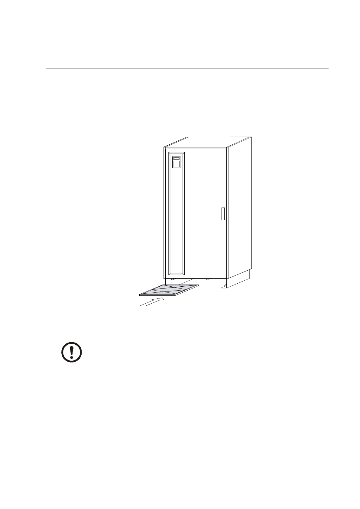
Air Filter
The air filter must be fitted at the air inlet of the UPS, and is designed for extra protection of UPS
systems installed in environments with conductive dust.
Fitting the air filter
Insert the air filter in the brackets and slide it completely into the UPS enclosure.
The air filter can be mounted/replaced during normal operation of the UPS.
Note
990-2440 AIS 5000 400V Installation Manual 6
Page 13
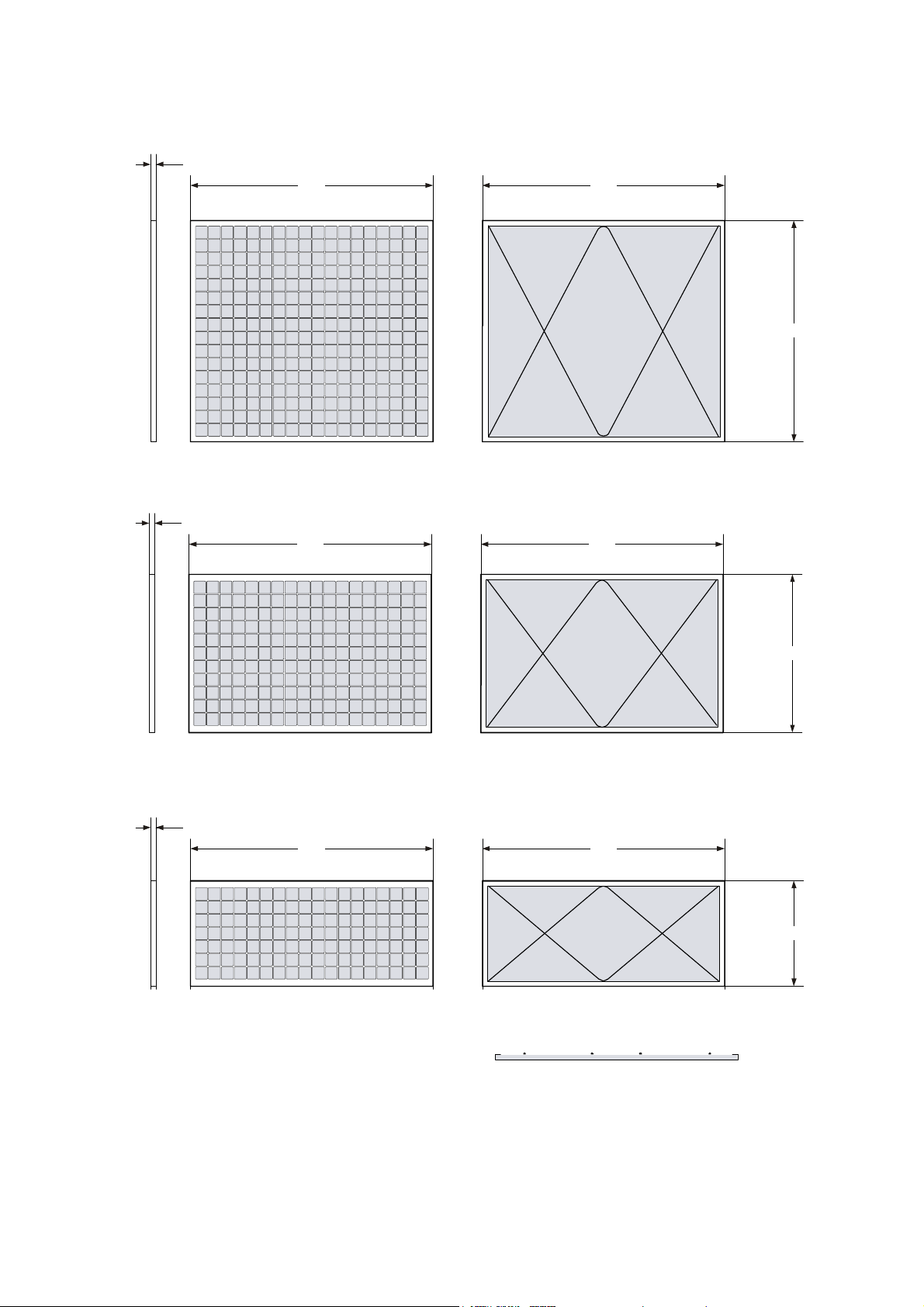
Air filter sizes
A
A
A
F
t si
d
A
15 mm
700 mm
For 40-100 kVA
General Information - Air Filter
700 mm
Front side
e
ron
15 mm
Bottom Side
700 mm
Bottom Side
For 10-30 kVA
ir filter
Upper Side
700 mm
ir filter
Upper Side
630 mm
450 mm
15 mm
700 mm
For 80-100 kVA
700 mm
ir filter
300 mm
Front side
Bottom Side Upper Side
(cut view)
990-2440 AIS 5000 400V Installation Manual 7
Page 14

General Information - Air Filter
A
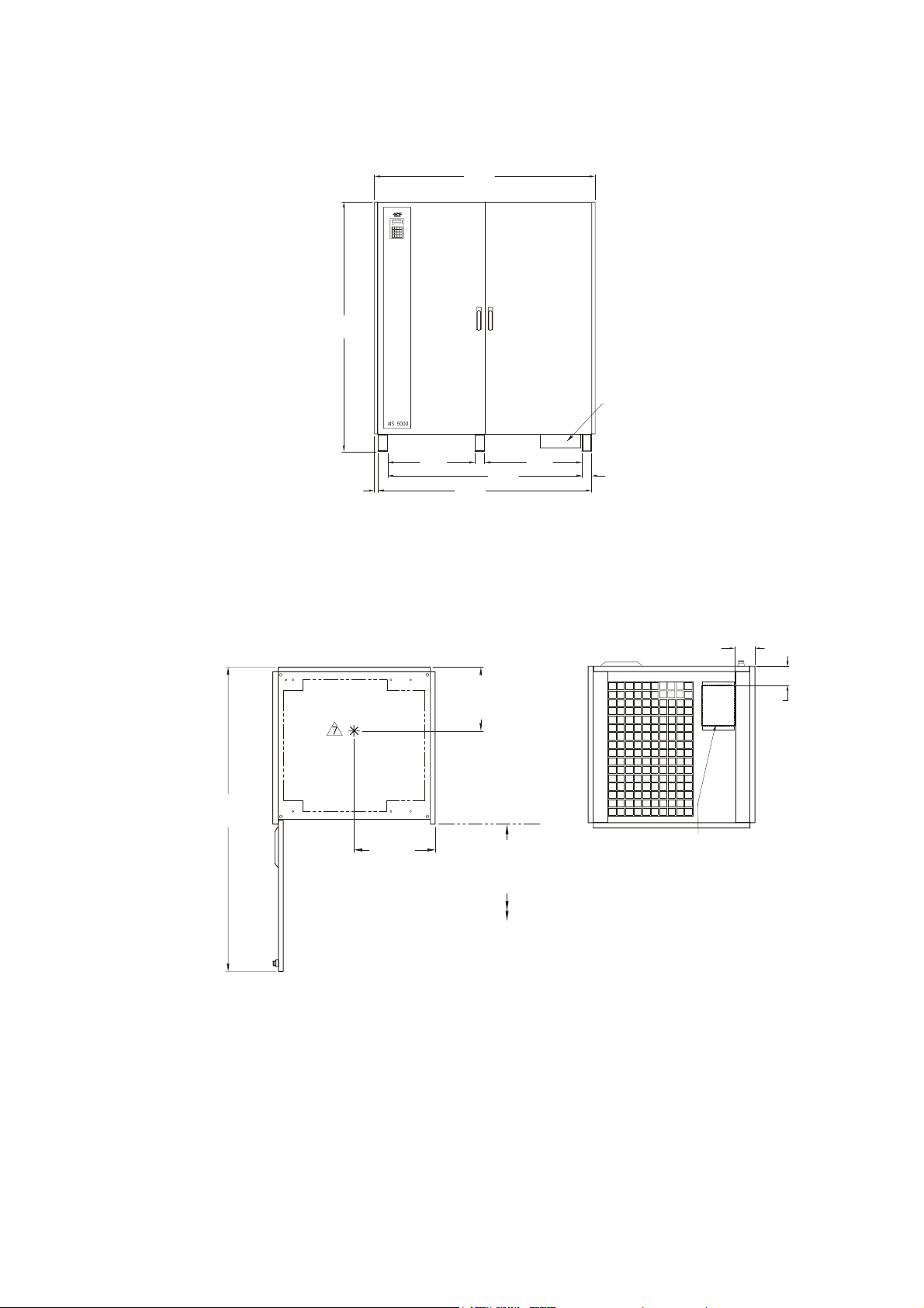
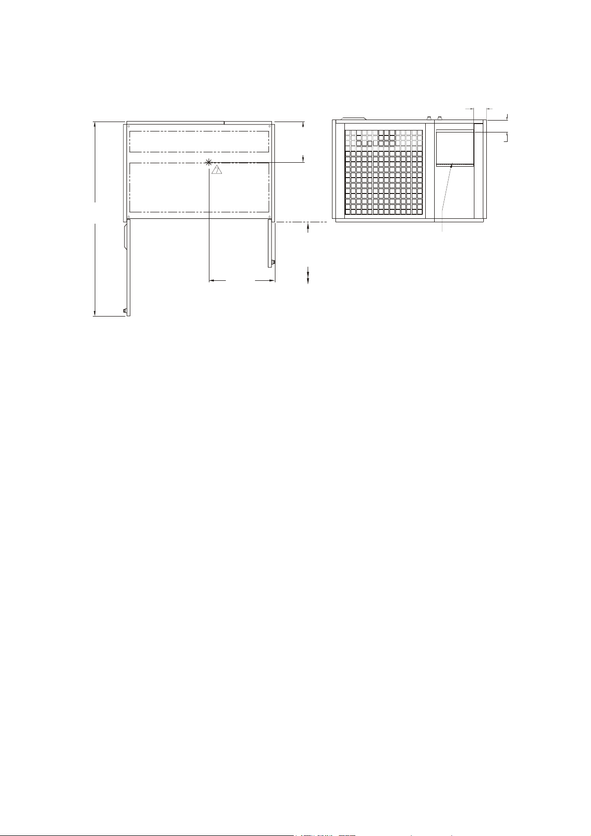
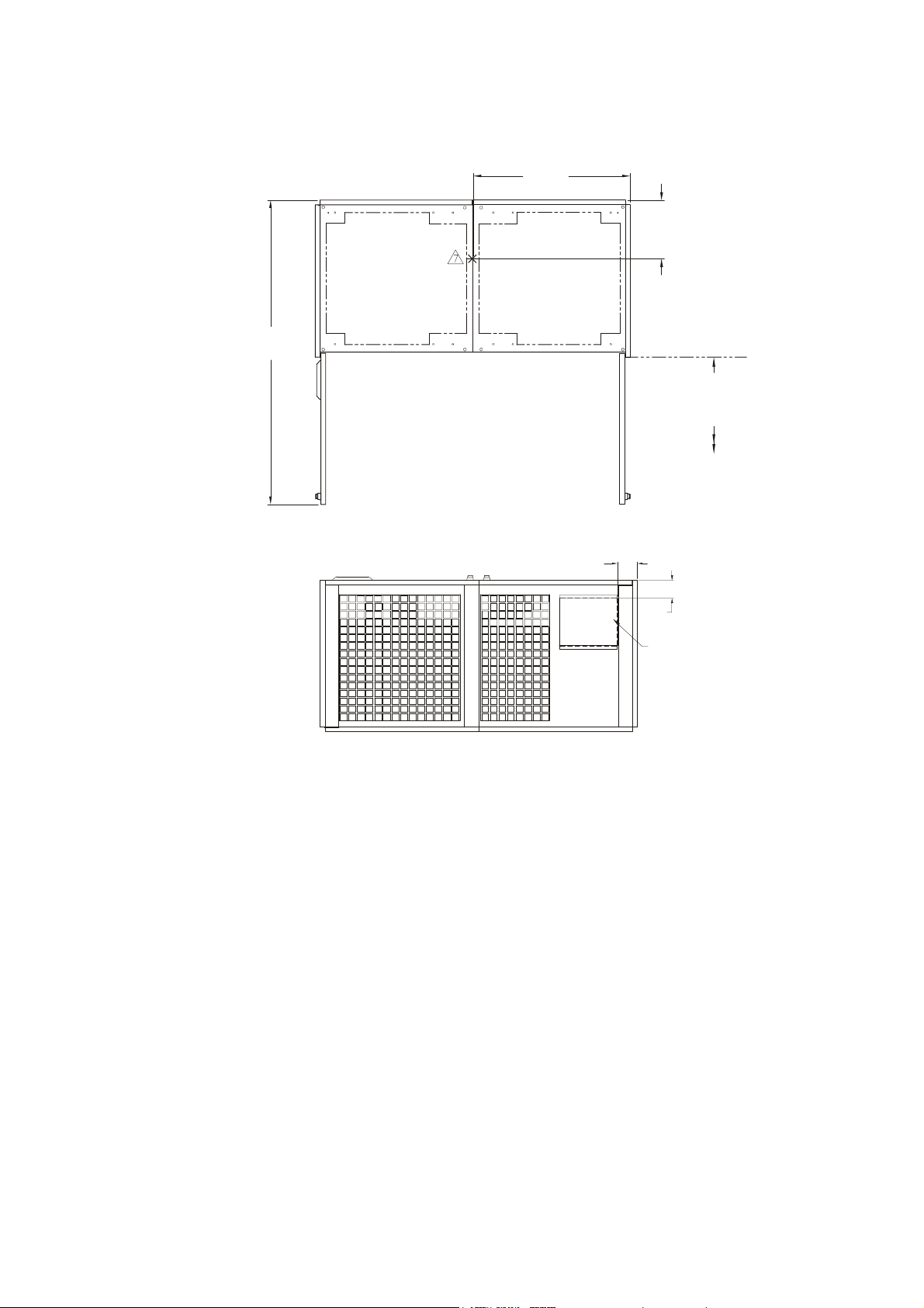
Enclosure dimensions and footprint
Enclosure dimensions.
UPS Height (mm) Width (mm) Depth (mm) Weight (kg)
10 kVA 1,803 826 813 550
20 kVA 1,803 826 813 650
30 kVA 1,803 826 813 750
40 kVA 1,803 1,219 813 900
60 kVA 1,803 1,219 813 1,100
80 kVA 1,803 1,626 813 1,300
100 kVA 1,803 1,626 813 1,500
71
(1,803)
1.00
(25)
10-30kV
32.50
(826)
24.99
(635)
30.52
(775)
Conduit Box
2.76
(70)
71
(1,803)
1.00
(25)
40-60kVA
48
(1,219)
24.99
(635)
39.90
(1,013)
45.43
(1,154)
12.14
(308)
Conduit Box
2.76
(70)
8 AIS 5000 400V Installation Manual 990-2440
Page 15
71
(1,803)
80-100kVA
64
(1,626)
General Information - Air Filter
Conduit Box
24.99
(635)
1.00
(25)
Footprint.
Top and bottom view of 10–30kVA UPS:
Perforated area
for air circulation
61.00
(1,549)
16.26
(413)
COG-X
(1,414)
61.19
(1,554)
12.80
(325)
COG-Z
36.00 (914)
Minimum
service
clearance
55.66
27.91
(709)
2.76
(70)
3.96
(100)
3.76
(95)
Conduit Box
990-2440 AIS 5000 400V Installation Manual 9
Page 16
General Information - Air Filter
Top and bottom view of 40–60kVA UPS:
3.96
(100)
61.00
(1,549)
Perforated area
for air circula tion
Perforated area
for air circulation
20.67
(525)
COG-X
12.80
(325)
COG-Z
36.00 (914)
Minimum
service
clerance
3.76
(95)
Conduit Box
10 AIS 5000 400V Installation Manual 990-2440
Page 17
Top and bottom view of 80–100kVA UPS:
Perforated ar ea
for air circulation
61.00
(1,549)
31.50
(800)
COG-X
Perforated ar ea
for air circulation
General Information - Air Filter
11.81
(300)
COG-Z
36.00 (914)
Minimum
service
clearance
3.96
(100)
3.76
(95)
Conduit Box
990-2440 AIS 5000 400V Installation Manual 11
Page 18
External Connection
Connecting the UPS
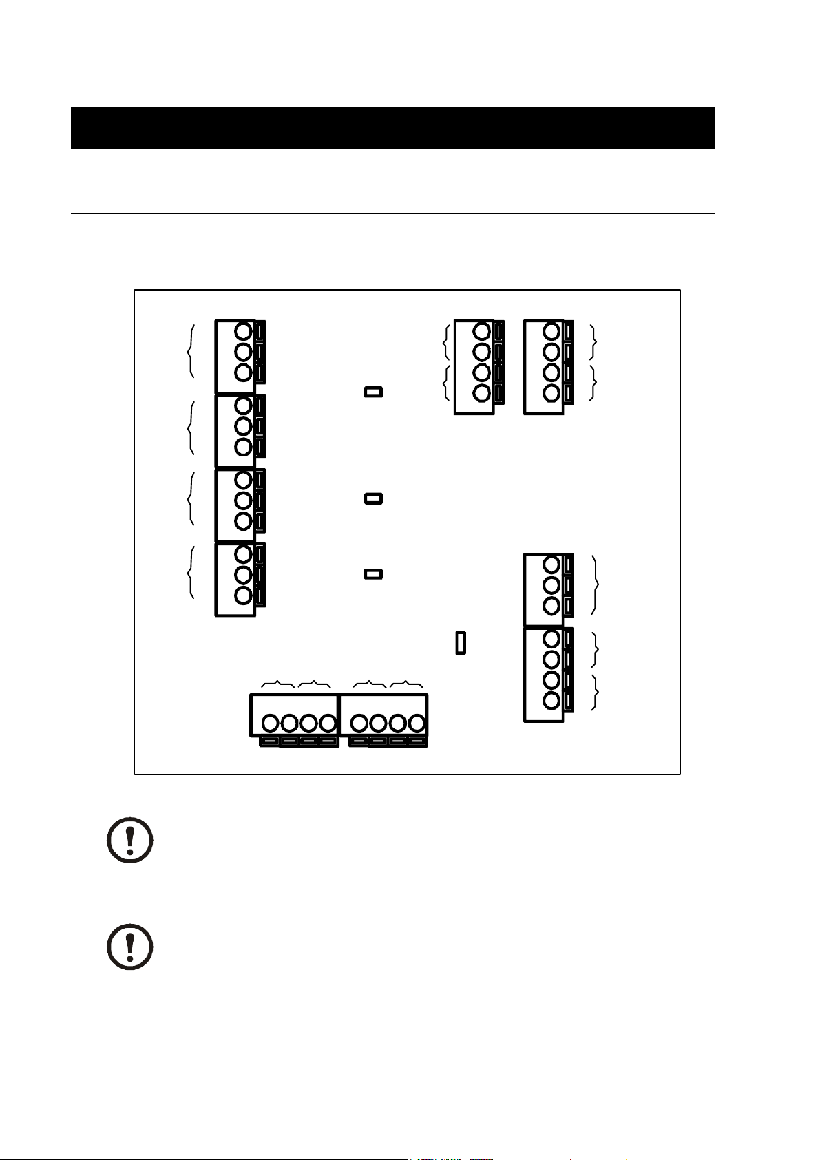
External connection board
Common
Fau lt
Status:
Alarm
Common
Fa ul t
Status:
Alarm
Battery
Operation
External
Contac torbypass
011
012
014
X00 1
021
022
024
X00 2
031
032
034
X00 3
041
042
044
X00 4
Battery temp.
compensation
H001
H003
H004
Output Switch
Coupling Switch
1 2 3 4 1 2 3 4
X009
Output Switc h
X011
Battery
MCCB
pos.
indication
Coupling Switch
X007 X008
SW01
Serivce
Switch pos.
indication
Analog
1 2 3 4
1 2 3 4
AUX4 inp ut
Remote
Control
1 2 3
X00 5
Emergency
Shut Down
Internal Supply
Emergency
Shut Down
1 2 3 4
External
X00 6
Supply 12Vdc
or 24Vdc
X001–X004 are relay change-over contacts 2A, 250Vac (0, 5A, 60Vdc). X006 is
Emergency Power Off (EPO) on the input. X007 pin 3–4 for Battery Temperature Sensor.
Note
Use 1.5 mm CU conductors only.
Note
12 AIS 5000 400V Installation Manual 990-2440
Page 19
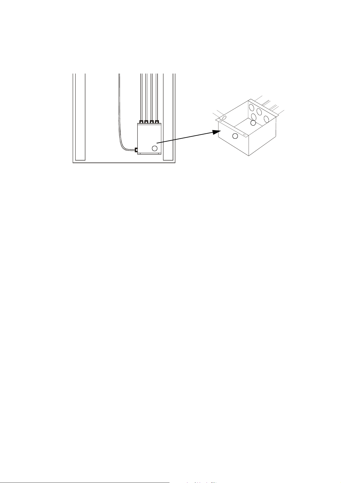
Installing Conduit Boxes
Top view:
External Connection - Connecting the UPS
UPS Feet
Conduit Box
Front of Conduit Box
In p u t
Comm.
DC
Output
Bypass
990-2440 AIS 5000 400V Installation Manual 13
Page 20
External Connection - Connecting the UPS
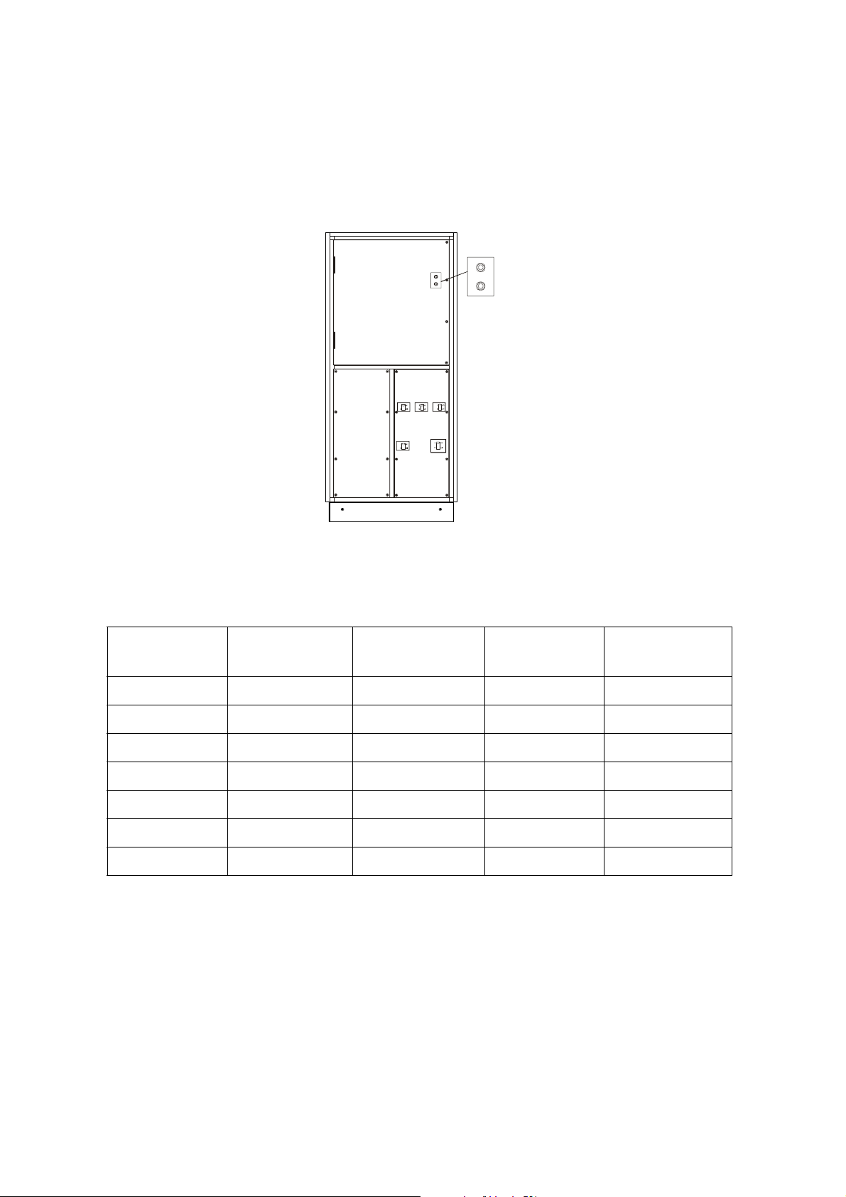
Mounting the Conduit Box:
1. Open UPS front door.
2. Remove cover from the input/output section.
S001
S002
0
S002
0
0
0
1
1
S001
1
1
In order to remove the cover from the inand output section, please remove all 8
M6×12 torx screws.
3. Place Conduit Box under UPS and align it with hole in UPS bottom plate.
4. Take out Conduit Box and make holes in Conduit Box according to below table.
Conduit sizes (mm):
Input Conduit
Output/Bypass
Conduit
Battery
Conduit
Alarm Conduit
10 kVA 12.7 12.7 12.7 12.7
20 kVA 19.05 12.7 25.4 12.7
30 kVA 25.4 19.05 31.75 12.7
40 kVA 25.4 25.4 38.1 12.7
60 kVA 31.75 25.4 63.5 12.7
80 kVA 38.1 31.75 2 × 38.1 12.7
100 kVA 38.1 31.75 2 × 50 12.7
14 AIS 5000 400V Installation Manual 990-2440
Page 21

External Connection - Connecting the UPS
5. Install Conduit Box under UPS. Push projecting edge of Conduit Box into slot on UPS bottom
plate. From inside the UPS, mount front of Conduit Box onto UPS bottom plate using 2 M4×12
cross head screws for 10–30 kVA and 3 M4×12 cross head screws for 40–100 kVA.
6. Mount conduits.
7. Feed cables.
8. Install cables according to the procedures described in the following sections.
Access to Input/Output section
To access cable terminals, open front door, remove screws and lift off front cover (remember earth
wire on rear side).
Remember to remount front cover (and earth wire) before system start-up.
Caution
CAUTION!
Ensure correct phase rotation of utility input voltage! Max. power cable size: see section
with technical specifications starting on page 24.
990-2440 AIS 5000 400V Installation Manual 15
Page 22
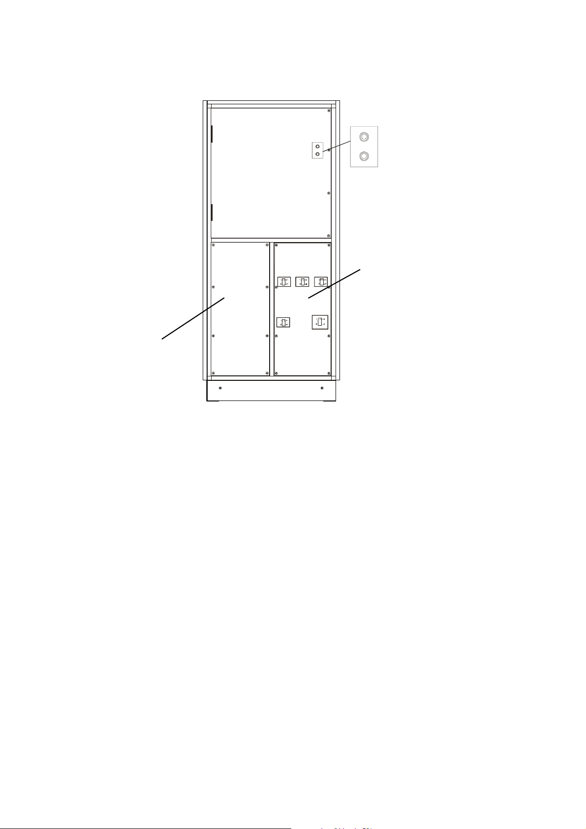
External Connection - Connecting the UPS
Low-voltage section behind
cover (Communication
Interface, EPO).
1
1
1
1
S001
S002
0
0
S001
S002
0
0
Input and Output section (high-voltage
section) behind cover.
16 AIS 5000 400V Installation Manual 990-2440
Page 23
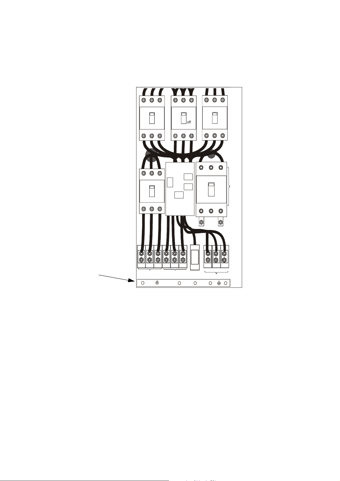
Connecting cables
Input/Output section 10–30 kVA
External Connection - Connecting the UPS
Q090
1
0onoff
Q001
1
0onoff
Q050
1
0
Q100
Q004
1
0
on
1
0
off
on
Battery
off
B-
on
B+
Grounding Busbar
• X001 Mains Input (L1, L2, L3)
• X090 Bypass Input L1, L2, L3, N)
• X004 Output (L1, L2, L3, N)
• Q004 Battery (+, –)
X001
X090
L1
L3
N
L2
X004
990-2440 AIS 5000 400V Installation Manual 17
Page 24
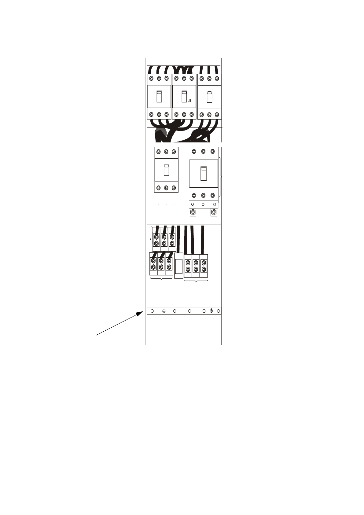
External Connection - Connecting the UPS
Input/Output section 40–60 kVA
X001
Q090
1
0onoff
1
0onoff
Q001
Q050
1
0
Q100
on
B+
Q004
1
0
on
1
0
off
on
Battery
off
B-
Grounding Busbar
• X001 Mains Input (L1, L2, L3)
• X090 Bypass Input (L1, L2, L3, N)
• X004 Output (L1, L2, L3, N)
• Q004 Battery (+, –)
X090
L2 L3
L1
X004
N
18 AIS 5000 400V Installation Manual 990-2440
Page 25
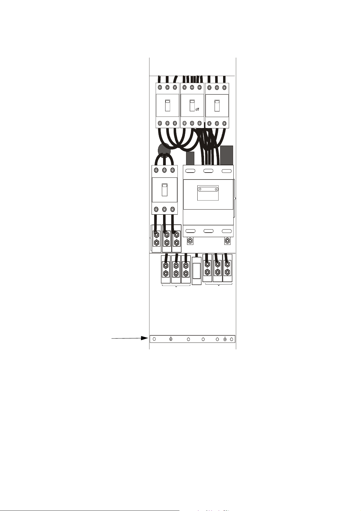
Input/Output section 80–100 kVA
External Connection - Connecting the UPS
X001
Q090
1
0onoff
Q001
1
0onoff
Q050
1
0
1
0
B+ B-
Q100
on
Q004
on
1
0
off
on
Batter y
off
Grounding Busbar
• X001 Mains Input (L1, L2, L3)
• X090 Bypass Input (L1, L2, L3, N)
• X004 Output (L1, L2, L3, N)
• Q004 Battery (+, –)
X090
N
L1 L2 L3
X004
990-2440 AIS 5000 400V Installation Manual 19
Page 26

External Connection - Connecting the UPS
Terminals.
Input X001/Output
X004/Bypass Input
Battery Q004
X090
10 kVA M6 Direct on breaker
terminals
20 kVA M6 Direct on breaker
terminals
30 kVA M6 Direct on breaker
terminals
40 kVA M8 Direct on breaker
terminals
60 kVA M8 Direct on breaker
terminals
80 kVA M10 Direct on breaker
terminals
100 kVA M10 Direct on breaker
terminals
Protective Earth
PE
Direct on Earth Busbar
Direct on Earth Busbar
Direct on Earth Busbar
Direct on Earth Busbar
Direct on Earth Busbar
Direct on Earth Busbar
Direct on Earth Busbar
The UPS input / bypass input is 4-Wire + Ground.
Note
Torque specifications.
Stud size 6 mm 8 mm 10 mm 12 mm
Torque 66/7.5 lb-in/Nm 133/15 lb-in/Nm 266/30 lb-in/Nm 443/50 lb-in/Nm
Grounding
System grounding:
Grounding busbar marked “Grounding” must be connected by grounding electrode conductor to a
local grounding electrode. Grounding electrode conductor to be supplied by the customer. (See
grounding busbar on illustrations starting on page 17).
20 AIS 5000 400V Installation Manual 990-2440
Page 27

External Connection - Connecting the UPS
Emergency Power Off (EPO)
The UPS is equipped with and EPO input (X006) on the external connection board (part of the low-
voltage section). The battery breaker is equipped with a shunt trip function (X061: 3, 4).
Communication interface
Shunt Trip function (120Vac)
The 3-port communication interface (located in the low voltage section) is used when an interaction
between UPS and an electrical device has to be established. The main purpose is to ensure a
controlled shut-down of the device in case of failures in the mains power supply.
990-2440 AIS 5000 400V Installation Manual 21
Page 28

External Connection - Connecting the UPS
Communication interface ports
COM-PORT: X005
The com-port consists of 4 relay outputs from which the following information is available:
– UPS System ON/OFF
– Normal Operation/Bypass Operation
– Normal Operation/Battery Operation
– Battery Voltage OK/Battery Voltage low
One input is for remote shut-down of the UPS system.
Normally, the COM-PORT is used in connection with the automatic shut-down of computers in case
of extended mains failures.
Serial Interface 20 mA Current Loop: X004
This interface consists of a 0-20mA Current loop with galvanic isolation. Information on the UPS-
measured values is available on this interface.
Multicom RS232: X003
X003 is normally used for the optional smartslot, but can be used for other purposes in its place. This
interface also has galvanic isolation and provides information on the UPS condition and measured
values.
For further information on these 2 interfaces, a protocol can be requested from APC.
Note
22 AIS 5000 400V Installation Manual 990-2440
Page 29

Overview of Communication interface
External Connection - Connecting the UPS
COM INTERFACE
X005 X004
COM PORT
X003
X003
X004
X005
25 pin SUB-D male
25 pin SUB-D male
25 pin SUB-D female
MULTICOM,
Serial Port: RS 232, V24
(normally used for optional smartslot)
Serial Port: 0 to 20mA current loop
14
NC1
C
15
NO1
C
C
2
COM1
16
NC2
C
C
17
NO2
C
4
COM2
18
NC3
C
C
19
NO3
C
6
COM3
20
NC4
C
21
NO4
C
C
8
COM4
13
C
25
C
"OFF" (2 - 14)
"ON" (2 - 15)
"Normal Operation" (4-16)
"Bypass Operation" (4-17)
"Normal Operation" (6-18)
"Battery Operation" (6-19)
"Battery Voltage OK" (8-20)
"Battery Voltage Low" (8-21)
+
Remote UPS shut down input
3,5 to 25V pulse IN at min. 1 sec.
-
Relay Contacts
990-2440 AIS 5000 400V Installation Manual 23
Page 30

10kVA 400V UPS
IS10KH
Performance - Linear Load
DC to AC Efficiency [%] 87.0
AC to AC Efficiency [%] 83.0
Heat Dissipation [BTU/h] [W] 6,003/1,758
Electrical Input
Mains
Voltage 400 V 3 Wire + G
P Nom. 10.3 kW
I Nom.
(Nominal input current based on nominal mains
voltage and batteries fully charged at 100% ohmic
load)
17.7 A
I Max.
(Maximum input current based on full battery
recharge and nominal mains voltage at 100% ohmic
load)
Over-Current protection [A]
(Based on continuous full load)
19.9 A
20 A
Input Voltage Range + 10%, -15% programmable
Input Frequency 50 Hz +
6% programmable
Current Distortion < 12%
Power Factor 0.8 - 0.9
Bypass
Voltage 400 V 3 Wire + N + G
I Nom 14.4 A
Over-Current protection [A]
(Based on continuous full load)
Bypass Voltage Range +
15 A
10% programmable
Electrical Output
Voltage 400 V 3 Wire + N + G
Nominal Current
(The output Current is based on the nominal apparent
power of the UPS)
14.4 A
Frequency Range 50Hz (adjustable 0.25, 0.50, 1-8%)
990-2440 AIS 5000 400V Installation Manual 24
Page 31

Electrical Output
Frequency Regulation 50 Hz, + 0.1% free running
External Connection - 10kVA 400V UPS
Output Voltage Range 100% static symmetrical load +
1%, 100% static asymmetrical load
+ 3%, no load to full load + 4%
Output Harmonic Distortion <3% linear load <5%
Load Crest Factor 5: 1
Load Power Factor 0.9 leading to 0.7 lagging
Overload Capacity 150% for 1 min., 125% for 10 min., Bypass Operation 1000% for 5
cycles
Connection Type 3 PH + N + G
Battery - External Only
Nominal Voltage
(Nominal battery voltage assumed to be 2.0 V/cell
(lead technology)
240 V
Number of Battery Cells 120
Float Charge Voltage 272 Volt DC programmable
Charge Voltage Range 100 to 115% of the DC nominal Voltage, +
1% IU characteristic
Low Battery Warning Range 210-222 Vdc (Factory Setting 210 V)
Low Battery Shutdown 204 Vdc
Full Load (P)
(The battery power takes in to account the DC-AC
efficien cy of the main inverter for linear load)
9.2 kW
Recommended Breaker Size [A] 60 A
Connection Type Hard Wire 3-wire (DC+/- + G)
Nominal Discharge Current [A]
(The battery nominal discharge current is based on
the nominal cell Voltage of 2.0 V/cell - number
of cells = 120 which gives a total Voltage of 240V)
Max. Discharge Current [A]
(The battery max. discharge current is based on a cell
end Voltage of 1.70V/cell which gives a total Voltage
of 204V)
38 A
46 A
Communication and Management
Control Panel Multi-function LCD status and control console
RS232 Port Yes
Network Management Card 10/100
Yes
Base T
Audible Alarm Audible and visible alarms prioritized by severity
Slots Empty 1
Modbus/BMS Card Optional
990-2440 AIS 5000 400V Installation Manual 25
Page 32

External Connection - 10kVA 400V UPS
Communication and Management
Emergency Power Off (EPO) Yes
Physical Values
Dimensions (H × W × D)
Unit 1,800 × 825 × 810 mm
Shipping 2,080 × 1,016 × 1,016 mm
Weight
Unit 550 kg
Shipping 590 kg
Max. Power Cable size [mm] 10
Recommended Cable sizes
Ext. Input Cable [mm] 2.5
Ground Cable [mm] 10
Ext. Output Cable [mm] 2.5
Ext. Battery Cable [mm] 10
Ext. Alarm Cable Max. [mm] 1.5
Recommended Conduit sizes
Input 1/2”
Output/Bypass 1/2”
Battery 1/2”
Alarm 1/2”
Environmental Values
Temperature
o
Operating 0
Storage -40
- 40o C
o
- 70o C
Elevation
Operating 0 - 1,000 m
Storage 0 - 5,000 m
Humidity Max. 95% non-conditioned
Protection Class IP30 (IP32 optional)
Transient Attenuation Differential mode 60 to 80 dB, Common mode 120 dB
Audible Noise at 3.28 feet (1 m) 60-70 dB, depending on type
Compliance
Approvals IEC 62040/EN 50091 Class A, VFI-SS-112
26 AIS 5000 400V Installation Manual 990-2440
Page 33

External Connection - 10kVA 400V UPS
Options
IP32 Roof 864 × 864 mm
Relay Boards 2 relay boards with each 16 dry contacts
Modbus/BMS Card
990-2440 AIS 5000 400V Installation Manual 27
Page 34

20kVA 400V UPS
IS20KH
Performance - Linear Load
DC to AC Efficiency [%] 89.0
AC to AC Efficiency [%] 85.3
Heat Dissipation [BTU/h] [W] 9,923/2,905
Electrical Input
Mains
Voltage 400 V 3 Wire + G
P Nom. 19.88 kW
I Nom.
(Nominal input current based on nominal mains
voltage and batteries fully charged at 100% ohmic
load)
33.79 A
I Max.
(Maximum input current based on full battery
recharge and nominal mains voltage at 100% ohmic
load)
Over-Current protection [A]
(Based on continuous full load)
39.4 A
40 A
Input Voltage Range + 10%, -15% programmable
Input Frequency 50 Hz +
6% programmable
Current Distortion < 12%
Power Factor 0.8 - 0.9
Bypass
Voltage 400 V 3 Wire + N + G
I Nom. 28.9 A
Over-Current protection [A]
(Based on continuous full load)
Bypass Voltage Range +
30 A
10% programmable
Electrical Output
Voltage 400 V 3 Wire + N + G
Nominal Current
(The output Current is based on the nominal apparent
power of the UPS)
28.9 A
Frequency Range 50Hz (adjustable 0.25, 0.50, 1-8%)
28 AIS 5000 400V Installation Manual 990-2440
Page 35

Electrical Output
Frequency Regulation 50 Hz, + 0.1% free running
External Connection - 20kVA 400V UPS
Output Voltage Range 100% static symmetrical load +
1%, 100% static asymmetrical load
+ 3%, no load to full load + 4%
Output Harmonic Distortion <3% linear load <5%
Load Crest Factor 5: 1
Load Power Factor 0.9 leading to 0.7 lagging
Overload Capacity 150% for 1 min., 125% for 10 min., Bypass Operation 1000% for 5
cycles
Connection Type 3 PH + N + G
Battery - External Only
Nominal Voltage
(Nominal battery voltage assumed to be 2.0 V/cell
(lead technology)
240 V
Number of Battery Cells 120
Float Charge Voltage 272 Volt DC programmable
Charge Voltage Range 100 to 115% of the DC nominal Voltage, +
1% IU characteristic
Low Battery Warning Range 210 - 222 Vdc (Factory Setting 210 V)
Low Battery Shutdown 204 Vdc
Full Load (P)
(The battery power takes in to account the DC-AC
efficien cy of the main inverter for linear load)
18.0 kW
Recommended Breaker Size [A] 125 A
Connection Type Hard Wire 3-wire (DC+/- + G)
Nominal Discharge Current [A]
(The battery nominal discharge current is based on
the nominal cell Voltage of 2.0 V/cell - number
of cells = 120 which gives a total Voltage of 240V)
Max. Discharge Current [A]
(The battery max. discharge current is based on a cell
end Voltage of 1.70V/cell which gives a total Voltage
of 204V)
75 A
91 A
Communication and Management
Control Panel Multi-function LCD status and control console
RS232 Port Yes
Network Management Card 10/100
Yes
Base T
Audible Alarm Audible and visible alarms prioritized by severity
Slots Empty 1
Modbus/BMS Card Optional
990-2440 AIS 5000 400V Installation Manual 29
Page 36

External Connection - 20kVA 400V UPS
Communication and Management
Emergency Power Off (EPO) Yes
Physical Values
Dimensions (H × W × D)
Unit 1,800 × 825 × 810 mm
Shipping 2,080 × 1,016 × 1,016 mm
Weight
Unit 650 kg
Shipping 690 kg
Max. Power Cable size [mm] 25
Recommended Cable sizes
Ext. Input Cable [mm] 4
Ground Cable [mm] 10
Ext. Output Cable [mm] 4
Ext. Battery Cable [mm] 25
Ext. Alarm Cable Max. [mm] 1.5
Recommended Conduit sizes
Input 1”
Output 1/2”
Battery 1”
Alarm 1/2”
Environmental Values
Temperature
o
Operating 0
Storage -40
- 40o C
o
- 70o C
Elevation
Operating 0 - 1,000 m
Storage 0 - 5,000 m
Humidity Max. 95% non-conditioned
Protection Class IP30 (IP32 optional)
Transient Attenuation Differential mode 60 to 80 dB, Common mode 120 dB
Audible Noise at 3.28 feet (1 m) 60-70 dB, depending on type
Compliance
Approvals IEC 62040/EN 50091 Class A, VFI-SS-112
30 AIS 5000 400V Installation Manual 990-2440
Page 37

External Connection - 20kVA 400V UPS
Options
IP32 Roof 864 × 864 mm
Relay Boards 2 relay boards with each 16 dry contacts
Modbus/BMS Card
990-2440 AIS 5000 400V Installation Manual 31
Page 38

30kVA 400V UPS
IS30KH
Performance - Linear Load
DC to AC Efficiency [%] 89.4
AC to AC Efficiency [%] 85.7
Heat Dissipation [BTU/h] [W] 13,833/4,050
Electrical Input
Mains
Voltage 400 V 3 Wire + G
P Nom. 28.35 kW
I Nom.
(Nominal input current based on nominal mains
voltage and batteries fully charged at 100% ohmic
load)
47.86 A
I Max.
(Maximum input current based on full battery
recharge and nominal mains voltage at 100% ohmic
load)
Over-Current protection [A]
(Based on continuous full load)
59.9 A
60 A
Input Voltage Range + 10%, -15% programmable
Input Frequency 50 Hz +
6% programmable
Current Distortion < 12%
Power Factor 0.8 - 0.9
Bypass
Voltage 400 V 3 Wire + N + G
I Nom 43.3 A
Over-Current protection [A]
(Based on continuous full load)
Bypass Voltage Range +
45 A
10% programmable
Electrical Output
Voltage 400 V 3 Wire + N + G
Nominal current
(The output current is based on the nominal apparent
power of the UPS)
43.3 A
Frequency Range 50Hz (adjustable 0.25, 0.50, 1-8%)
32 AIS 5000 400V Installation Manual 990-2440
Page 39

Electrical Output
Frequency Regulation 50 Hz, + 0.1% free running
External Connection - 30kVA 400V UPS
Output Voltage Range 100% static symmetrical load +
1%, 100% static asymmetrical load
+ 3%, no load to full load + 4%
Output Harmonic Distortion <3% linear load <5%
Load Crest Factor 5: 1
Load Power Factor 0.9 leading to 0.7 lagging
Overload Capacity 150% for 1 min., 125% for 10 min., Bypass Operation 1000% for 5
cycles
Connection Type 3 PH + N + G
Battery - External Only
Nominal Voltage
(Nominal battery voltage assumed to be 2.0 V/cell
(lead technology)
240 V
Number of Battery Cells 120
Float Charge Voltage 272 Volt DC programmable
Charge Voltage Range 100 to 115% of the DC nominal Voltage, +
1% IU characteristic
Low Battery Warning Range 210 - 222 Vdc (Factory Setting 210 V)
Low Battery Shutdown 204 Vdc
Full Load (P)
(The battery power takes in to account the DC-AC
efficien cy of the main inverter for linear load)
26.7 kW
Recommended Breaker Size [A] 150 A
Connection Type Hard Wire 3-wire (DC+/- + G)
Nominal Discharge Current [A]
(The battery nominal discharge current is based on
the nominal cell Voltage of 2.0 V/cell - number of
cells = 120 which gives a total Voltage of 240V)
Max. Discharge Current [A]
(The battery max. discharge current is based on a cell
end Voltage of 1.70V/cell which gives a total Voltage
of 204V)
111 A
135 A
Communication and Management
Control Panel Multi-function LCD status and control console
RS232 Port Yes
Network Management Card 10/100
Yes
Base T
Audible Alarm Audible and visible alarms prioritized by severity
Slots Empty 1
Modbus/BMS Card Optional
990-2440 AIS 5000 400V Installation Manual 33
Page 40

External Connection - 30kVA 400V UPS
Communication and Management
Emergency Power Off (EPO) Yes
Physical Values
Dimensions (H × W × D)
Unit 1,800 × 825 × 810 mm
Shipping 2,080 × 1,016 × 1,016 mm
Weight
Unit 750 kg
Shipping 790 kg
Max. Power Cable size [mm] 50
Recommended Cable sizes
Ext. Input Cable [mm] 10
Ground Cable [mm] 10
Ext. Output Cable [mm] 10
Ext. Battery Cable [mm] 50
Ext. Alarm Cable Max. [mm] 1.5
Recommended Conduit sizes
Input 1.25”
Output 3/4”
Battery 1.25”
Alarm 1/2”
Environmental Values
Temperature
o
Operating 0
Storage -40
- 40o C
o
- 70o C
Elevation
Operating 0 - 1,000 m
Storage 0 - 5,000 m
Humidity Max. 95% non-conditioned
Protection Class IP30 (IP32 optional)
Transient Attenuation Differential mode 60 to 80 dB, Common mode 120 dB
Audible Noise at 3.28 feet (1 m) 60-70 dB, depending on type
Compliance
Approvals IEC 62040/EN 50091 Class A, VFI-SS-112
34 AIS 5000 400V Installation Manual 990-2440
Page 41

External Connection - 30kVA 400V UPS
Options
IP32 Roof 864 × 864 mm
Relay Boards 2 relay boards with each 16 dry contacts
Modbus/BMS Card
990-2440 AIS 5000 400V Installation Manual 35
Page 42

40kVA 400V UPS
IS40KH
Performance - Linear Load
DC to AC Efficiency [%] 90.8
AC to AC Efficiency [%] 87.0
Heat Dissipation [BTU/h] [W] 16,333/4,782
Electrical Input
Mains
Voltage 400 V 3 Wire + G
P Nom. 36.9 kW
I Nom.
(Nominal input current based on nominal mains
voltage and batteries fully charged at 100% ohmic
load)
61.93 A
I Max.
(Maximum input current based on full battery
recharge and nominal mains voltage at 100% ohmic
load)
Over-Current protection [A]
(Based on continuous full load)
77.8 A
80 A
Input Voltage Range + 10%, -15% programmable
Input Frequency 50 Hz +
6% programmable
Current Distortion < 12%
Power Factor 0.8 - 0.9
Bypass
Voltage 400 V 3 Wire + N + G
I Nom 48.1 A
Over-Current protection [A]
(Based on continuous full load)
Bypass Voltage Range +
60 A
10% programmable
Electrical Output
Voltage 400 V 3 Wire + N + G
Nominal current
(The output current is based on the nominal apparent
power of the UPS)
57.7 A
Frequency Range 50Hz (adjustable 0.25, 0.50, 1-8%)
36 AIS 5000 400V Installation Manual 990-2440
Page 43

Electrical Output
Frequency Regulation 50 Hz, + 0.1% free running
External Connection - 40kVA 400V UPS
Output Voltage Range 100% static symmetrical load +
1%, 100% static asymmetrical load
+ 3%, no load to full load + 4%
Output Harmonic Distortion <3% linear load <5%
Load Crest Factor 5: 1
Load Power Factor 0.9 leading to 0.7 lagging
Overload Capacity 150% for 1 min., 125% for 10 min., Bypass Operation 1000% for 5
cycles
Connection Type 3 PH + N + G
Battery - External Only
Nominal Voltage
(Nominal battery voltage assumed to be 2.0 V/cell
(lead technology)
240 V
Number of Battery Cells 120
Float Charge Voltage 272 Volt DC programmable
Charge Voltage Range 100 to 115% of the DC nominal Voltage, +
1% IU characteristic
Low Battery Warning Range 210 - 222 Vdc (Factory Setting 210 V)
Low Battery Shutdown 204 Vdc
Full Load (P)
(The battery power takes in to account the DC-AC
efficien cy of the main inverter for linear load)
35.4 kW
Recommended Breaker Size [A] 200 A
Connection Type Hard Wire 3-wire (DC+/- + G)
Nominal Discharge Current [A]
(The battery nominal discharge current is based on
the nominal cell Voltage of 2.0 V/cell - number
of cells = 120 which gives a total Voltage of 240V)
Max. Discharge Current [A]
(The battery max. discharge current is based on a cell
end Voltage of 1.70V/cell which gives
a total Voltage of 204V)
147 A
179 A
Communication and Management
Control Panel Multi-function LCD status and control console
RS232 Port Yes
Network Management Card 10/100
Yes
Base T
Audible Alarm Audible and visible alarms prioritized by severity
Slots Empty 1
Modbus/BMS Card Optional
990-2440 AIS 5000 400V Installation Manual 37
Page 44

External Connection - 40kVA 400V UPS
Communication and Management
Emergency Power Off (EPO) Yes
Physical Values
Dimensions (H × W × D)
Unit 1,800 × 1,200 × 810 mm
Shipping 2,080 × 1,422 × 1,016 mm
Weight
Unit 900 kg
Shipping 950 kg
Max. Power Cable size [mm] 70
Recommended Cable sizes [mm]
Ext. Input Cable [mm] 16
Ground Cable [mm] 16
Ext. Output Cable [mm] 16
Ext. Battery Cable [mm] 70
Ext. Alarm Cable Max. [mm] 1.5
Recommended Conduit sizes
Input 1.25”
Output 1”
Battery 1.5”
Alarm 1/2”
Environmental Values
Temperature
o
Operating 0
Storage -40
- 40o C
o
- 70o C
Elevation
Operating 0 - 1,000 m
Storage 0 - 5,000 m
Humidity Max. 95% non-conditioned
Protection Class IP30 (IP32 optional)
Transient Attenuation Differential mode 60 to 80 dB, Common mode 120 dB
Audible Noise at 3.28 feet (1 m) 60-70 dB, depending on type
Compliance
Approvals IEC 62040/EN 50091 Class A, VFI-SS-112
38 AIS 5000 400V Installation Manual 990-2440
Page 45

External Connection - 40kVA 400V UPS
Options
IP32 Roof 1,270 × 864 mm
Relay Boards 2 relay boards with each 16 dry contacts
Modbus/BMS Card
990-2440 AIS 5000 400V Installation Manual 39
Page 46

60kVA 400V UPS
IS60KH
Performance - Linear Load
DC to AC Efficiency [%] 92.6
AC to AC Efficiency [%] 87.9
Heat Dissipation [BTU/h] [W] 22,338/6,541
Electrical Input
Mains
Voltage 400 V 3 Wire + G
P Nom. 54.42 kW
I Nom.
(Nominal input current based on nominal mains
voltage and batteries fully charged at 100% ohmic
load)
90.08 A
I Max.
(Maximum input current based on full battery
recharge and nominal mains voltage at 100% ohmic
load)
Over-Current protection [A]
(Based on continuous full load)
117 A
125 A
Input Voltage Range + 10%, -15% programmable
Input Frequency 50 Hz +
6% programmable
Current Distortion < 12%
Power Factor 0.8 - 0.9
Bypass
Voltage 400 V 3 Wire + N + G
I Nom 86.6 A
Over-Current protection [A]
(Based on continuous full load)
Bypass Voltage Range +
90 A
10% programmable
Electrical Output
Voltage 400 V 3 Wire + N + G
Nominal current
(The output current is based on the nominal apparent
power of the UPS)
86.6 A
Frequency Range 50Hz (adjustable 0.25, 0.50, 1-8%)
40 AIS 5000 400V Installation Manual 990-2440
Page 47

Electrical Output
Frequency Regulation 50 Hz, + 0.1% free running
External Connection - 60kVA 400V UPS
Output Voltage Range 100% static symmetrical load +
1%, 100% static asymmetrical load
+ 3%, no load to full load + 4%
Output Harmonic Distortion <3% linear load <5%
Load Crest Factor 5: 1
Load Power Factor 0.9 leading to 0.7 lagging
Overload Capacity 150% for 1 min., 125% for 10 min., Bypass Operation 1000% for 5
cycles
Connection Type 3 PH + N + G
Battery - External Only
Nominal Voltage
(Nominal battery voltage assumed to be 2.0 V/cell
(lead technology)
240 V
Number of Battery Cells 120
Float Charge Voltage 272 Volt DC programmable
Charge Voltage Range 100 to 115% of the DC nominal Voltage, +
1% IU characteristic
Low Battery Warning Range 210 - 222 Vdc (Factory Setting 210 V)
Low Battery Shutdown 204 Vdc
Full Load (P)
(The battery power takes in to account the DC-AC
efficien cy of the main inverter for linear load)
52.7 kW
Recommended Breaker Size [A] 300 A
Connection Type Hard Wire 3-wire (DC+/- + G)
Nominal Discharge Current [A]
(The battery nominal discharge current is based on
the nominal cell Voltage of 2.0 V/cell - number
of cells = 120 which gives a total Voltage of 240V)
Max. Discharge Current [A]
(The battery max. discharge current is based on a cell
end Voltage of 1.70V/cell which gives a total Voltage
of 204V)
220 A
266 A
Communication and Management
Control Panel Multi-function LCD status and control console
RS232 Port Yes
Network Management Card 10/100
Yes
Base T
Audible Alarm Audible and visible alarms prioritized by severity
Slots Empty 1
Modbus/BMS Card Optional
990-2440 AIS 5000 400V Installation Manual 41
Page 48

External Connection - 60kVA 400V UPS
Communication and Management
Emergency Power Off (EPO) Yes
Physical Values
Dimensions (H × W × D)
Unit 1,800 × 1,200 × 810 mm
Shipping 2,080 × 1,422 × 1,016 mm
Weight
Unit 1,100 kg
Shipping 1,150 kg
Max. Power Cable size [mm] 120
Recommended Cable sizes
Ext. Input Cable [mm] 25
Ground Cable [mm] 25
Ext. Output Cable [mm] 16
Ext. Battery Cable [mm] 120
Ext. Alarm Cable Max. [mm] 1.5
Recommended Conduit sizes
Input 1.25”
Output 1”
Battery 2.5”
Alarm 1/2”
Environmental Values
Temperature
o
Operating 0
Storage -40
- 40o C
o
- 70o C
Elevation
Operating 0 - 1,000 m
Storage 0 - 5,000 m
Humidity Max. 95% non-conditioned
Protection Class IP30 (IP32 optional)
Transient Attenuation Differential mode 60 to 80 dB, Common mode 120 dB
Audible Noise at 3.28 feet (1 m) 60-70 dB, depending on type
Compliance
Approvals IEC 62040/EN 50091 Class A, VFI-SS-112
42 AIS 5000 400V Installation Manual 990-2440
Page 49

External Connection - 60kVA 400V UPS
Options
IP32 Roof 1,270 × 864 mm
Relay Boards 2 relay boards with each 16 dry contacts
Modbus/BMS Card
990-2440 AIS 5000 400V Installation Manual 43
Page 50

80kVA 400V UPS
IS80KH
Performance - Linear Load
DC to AC Efficiency [%] 91.0
AC to AC Efficiency [%] 87.9
Heat Dissipation [BTU/h] [W] 29,809/8,728
Electrical Input
Mains
Voltage 400 V 3 Wire + G
P Nom. 72.33 kW
I Nom.
(Nominal input current based on nominal mains
voltage and batteries fully charged at 100% ohmic
load)
118.23 A
I Max.
(Maximum input current based on full battery
recharge and nominal mains voltage at 100% ohmic
load)
Over-Current protection [A]
(Based on continuous full load)
152.8 A
160 A
Input Voltage Range + 10%, -15% programmable
Input Frequency 50 Hz +
6% programmable
Current Distortion < 12%
Power Factor 0.8 - 0.9
Bypass
Voltage 400 V 3 Wire + N + G
I Nom 115.5 A
Over-Current protection [A]
(Based on continuous full load)
Bypass Voltage Range +
125 A
10% programmable
Electrical Output
Voltage 400 V 3 Wire + N + G
Nominal current
(The output current is based on the nominal apparent
power of the UPS)
115.5 A
Frequency Range 50Hz (adjustable 0.25, 0.50, 1-8%)
44 AIS 5000 400V Installation Manual 990-2440
Page 51

Electrical Output
Frequency Regulation 50 Hz, + 0.1% free running
External Connection - 80kVA 400V UPS
Output Voltage Range 100% static symmetrical load +
1%, 100% static asymmetrical load
+ 3%, no load to full load + 4%
Output Harmonic Distortion <3% linear load <5%
Load Crest Factor 5: 1
Load Power Factor 0.9 leading to 0.7 lagging
Overload Capacity 150% for 1 min., 125% for 10 min., Bypass Operation 1000% for 5
cycles
Connection Type 3 PH + N + G
Battery - External Only
Nominal Voltage
(Nominal battery voltage assumed to be 2.0 V/cell
(lead technology)
240 V
Number of Battery Cells 120
Float Charge Voltage 272 Volt DC programmable
Charge Voltage Range 100 to 115% of the DC nominal Voltage, +
1% IU characteristic
Low Battery Warning Range 210 - 222 Vdc (Factory Setting 210 V)
Low Battery Shutdown 204 Vdc
Full Load (P)
(The battery power takes in to account the DC-AC
efficien cy of the main inverter for linear load)
69.9 kW
Recommended Breaker Size [A] 400 A
Connection Type Hard Wire 3-wire (DC+/- + G)
Nominal Discharge Current [A]
(The battery nominal discharge current is based on
the nominal cell Voltage of 2.0 V/cell - number
of cells = 120 which gives a total Voltage of 240V)
Max. Discharge Current [A]
(The battery max. discharge current is based on a cell
end Voltage of 1.70V/cell which gives a total Voltage
of 204V)
291 A
353 A
Communication and Management
Control Panel Multi-function LCD status and control console
RS232 Port Yes
Network Management Card 10/100
Yes
Base T
Audible Alarm Audible and visible alarms prioritized by severity
Slots Empty 1
Modbus/BMS Card Optional
990-2440 AIS 5000 400V Installation Manual 45
Page 52

External Connection - 80kVA 400V UPS
Communication and Management
Emergency Power Off (EPO) Yes
Physical Values
Dimensions (H × W × D)
Unit 1,800 × 1,600 × 810 mm
Shipping 2,080 × 1,830 × 1,016 mm
Weight
Unit 1,300 kg
Shipping 1,360 kg
Max. Power Cable size [mm] 2 × 70
Recommended Cable sizes
Ext. Input Cable [mm] 35
Ground Cable [mm] 35
Ext. Output Cable [mm] 25
Ext. Battery cable [mm] 2 × 70
Ext. Alarm Cable Max. [mm] 1.5
Recommended Conduit sizes
Input 1.5”
Output 1.25”
Battery 2 × 1.5”
Alarm 1/2”
Environmental Values
Temperature
o
Operating 0
Storage -40
- 40o C
o
- 70o C
Elevation
Operating 0 - 1,000 m
Storage 0 - 5,000 m
Humidity Max. 95% non-conditioned
Protection Class IP30 (IP32 optional)
Transient Attenuation Differential mode 60 to 80 dB, Common mode 120 dB
Audible Noise at 3.28 feet (1 m) 60-70 dB, depending on type
Compliance
Approvals IEC 62040/EN 50091 Class A, VFI-SS-112
46 AIS 5000 400V Installation Manual 990-2440
Page 53

External Connection - 80kVA 400V UPS
Options
IP32 Roof 1,676 × 864
Relay Boards 2 relay boards with each 16 dry contacts
Modbus/BMS Card
990-2440 AIS 5000 400V Installation Manual 47
Page 54

100kVA 400V UPS
IS100KH
Performance - Linear Load
DC to AC Efficiency [%] 90.7
AC to AC Efficiency [%] 87.5
Heat Dissipation [BTU/h] [W] 38,745/11,345
Electrical Input
Mains
Voltage 400 V 3 Wire + G
P Nom. 90.67 kW
I Nom.
(Nominal input current based on nominal mains
voltage and batteries fully charged at 100% ohmic
load)
146.38 A
I Max.
(Maximum input current based on full battery
recharge and nominal mains voltage at 100% ohmic
load)
Over-Current protection [A]
(Based on continuous full load)
193.9 A
200 A
Input Voltage Range + 10%, -15% programmable
Input Frequency 50 Hz +
6% programmable
Current Distortion < 12%
Power Factor 0.8 - 0.9
Bypass
Voltage 400 V 3 Wire + N + G
I Nom 144.3 A
Over-Current protection [A]
(Based on continuous full load)
Bypass Voltage Range +
160 A
10% programmable
Electrical Output
Voltage 400 V 3 Wire + N + G
Nominal current
(The output current is based on the nominal apparent
power of the UPS)
144.3 A
Frequency Range 50Hz (0.25, 0.50, 1-8%)
48 AIS 5000 400V Installation Manual 990-2440
Page 55

Electrical Output
Frequency Regulation 50 Hz, + 0.1% free running
External Connection - 100kVA 400V UPS
Output Voltage Range 100% static symmetrical load +
1%, 100% static asymmetrical load
+ 3%,no load to full load + 4%
Output Harmonic Distortion <3% linear load <5%
Load Crest Factor 5: 1
Load Power Factor 0.9 leading to 0.7 lagging
Overload Capacity 150% for 1 min., 125% for 10 min., Bypass Operation 1000% for 5
cycles
Connection Type 3 PH + N + G
Battery - External Only
Nominal Voltage
(Nominal battery voltage assumed to be 2.0 V/cell
(lead technology)
240 V
Number of Battery Cells 120
Float Charge Voltage 272 Volt DC programmable
Charge Voltage Range 100 to 115% of the DC nominal Voltage, +
1% IU characteristic
Low Battery Warning Range 210 - 222 Vdc (Factory Setting 210 V)
Low Battery Shutdown 204 Vdc
Full Load (P)
(The battery power takes in to account the DC-AC
efficien cy of the main inverter for linear load)
87.4 kW
Recommended Breaker Size [A] 500 A
Connection Type Hard Wire 3-wire (DC+/- + G)
Nominal Discharge Current [A]
(The battery nominal discharge current is based on
the nominal cell Voltage of 2.0 V/cell - number
of cells = 120 which gives a total Voltage of 240V)
Max. Discharge Current [A]
(The battery max. discharge current is based on a cell
end Voltage of 1.70V/cell which gives a total Voltage
of 204V)
364 A
442 A
Communication and Management
Control Panel Multi-function LCD status and control console
RS232 Port Yes
Network Management Card 10/100
Yes
Base T
Audible Alarm Audible and visible alarms prioritized by severity
Slots Empty 1
Modbus/BMS Card Optional
990-2440 AIS 5000 400V Installation Manual 49
Page 56

External Connection - 100kVA 400V UPS
Communication and Management
Emergency Power Off (EPO) Yes
Physical Values
Dimensions (H × W × D)
Unit 1,800 × 1,600 × 810 mm
Shipping 2,080 × 1,830 × 1,016 mm
Weight
Unit 1,500 kg
Shipping 1,575 kg
Max. Power Cable size [mm] 2 × 95
Recommended Cable sizes
Ext. Input Cable [mm] 70
Ground Cable [mm] 50
Ext. Output Cable [mm] 35
Ext. Battery Cable [mm] 2 × 95
Ext. Alarm Cable Max. [mm] 1.5
Recommended Conduit sizes
Input 2.50”
Output 1.25”
Battery 2 × 2”
Alarm 1/2”
Environmental Values
Temperature
o
Operating 0
Storage -40
- 40o C
o
- 70o C
Elevation
Operating 0 - 1,000 m
Storage 0 - 5,000 m
Humidity Max. 95% non-conditioned
Protection Class IP30 (IP32 optional)
Transient Attenuation Differential mode 60 to 80 dB, Common mode 120 dB
Audible Noise at 3.28 feet (1 m) 60-70 dB, depending on type
Compliance
Approvals IEC 62040/EN 50091 Class A, VFI-SS-112
50 AIS 5000 400V Installation Manual 990-2440
Page 57

External Connection - 100kVA 400V UPS
Options
IP32 Roof 1,676 × 846
Relay Boards 2 relay boards with each 16 dry contacts
Modbus/BMS Card
990-2440 AIS 5000 400V Installation Manual 51
Page 58

Options
For information on options and accessories available in your region, please contact APC - See “How
to Contact” on the back cover of this manual.
IP32 drip shields, Communication cards and Relay boards are described in the following.
52 AIS 5000 400V Installation Manual 990-2440
Page 59

IP32 Drip Shield
If the UPS is installed in an environment with dripping, non-corrosive liquids, install a IP32 drip
shield to prevent such non-corrosive liquids from dripping into the UPS.
To achieve protection IP32, the UPS must be equipped with the drip shield and an air filter at the
bottom.
For further information on air filter, see section on “Air Filter” on page 6.
990-2440 AIS 5000 400V Installation Manual 53
Page 60

Options - IP32 Drip Shield
Mounting the drip shield
Remove protection foil before assembly!
Mount sides on drip shield
(not shown on illustration)
x 4 x 4
v
Remove the 4 bolts from UPS drip shield and mount the 4 stand-offs.
Reuse bolts from UPS roof to attach drip shield
xc
x 4
x 4
v
xc
54 AIS 5000 400V Installation Manual 990-2440
Page 61

Drip shield sizes
m
Options - IP32 Drip Shield
Front View
Top View
775 mm
45 mm
85.1 mm 85.1 mm
100 mm
7.1 mm
100 mm
865.1 m
IP32 for 10 – 30 k VA and 80 – 100 kVA UPS
24.9 mm
840 mm
Front View
24.9 mm
Top View
400 mm
45 mm
85,1 mm
74.9 mm
840 mm
7.1 mm
74.9 mm
337.6 mm
IP32 for Batter y Enc l os u re
45 mm
74.9 mm
74.9 mm
Front View
Top View
1,150.1 mm
85.1 mm
7.1 mm
1,240 mm
IP32 for 40 – 60 kV A UPS
24.9 mm
85.1 mm
575 mm575 mm
840 mm
990-2440 AIS 5000 400V Installation Manual 55
Page 62

Relay Board
All alarms are shown in alarm position (*). Status is shown in status position ( ). All relay change-
over contacts are 2A 250 Vac or 0.5 60 Vdc. Maximum cable size is AWG 14 (2.5 mm
∆
2
).
LOW VOLTAGE SE CTION
Message:
Rectifier Mains Fault
DC Out of Tolerance
Rectifier Fuse Blown
Battery Discharged
Inverter Fuse Blown
Bypass Mains Fault
Overtemperature
Fan Failure
Power Supply Fault
Bypass Static Switch
Synchronized
Relay #
X001 X002 X003
2,5 2,5 2,5
011
012
013
021
022
024
031
032
X004
034
2,5 2,5
041
042
X005
044
051
052
X006 X007 X008 X009 X010
054
2,5 2,5
061
062
064
071
072
074
2,5 2,5 2,5 2,5
081
082
084
091
092
094
101
102
X011 X012 X013
104
111
112
114
2,52,52,52,52,5
121
122
124
131
132
X014 X01 5 X016
134
141
142
144
151
152
154
161
162
164
A077
K001 K002 K003 K004 K005 K006
****************
K007 K008 K009 K010 K011
K012 K013 K014 K015 K016
*
ALARM POSITION
56 AIS 5000 400V Installation Manual 990-2440
Page 63

A
Message:
Output Static Switch
Inhibited
Bypass Static Switch
Inhibited
Asynchronous
Overload Inv/Bypas s
Inverter Fault
Battery Operation
Rectifier Failure
EN ON
EA ON
Inverter ON
Boost Charge ON
Charger ON
External Horn
Relay #
X001 X002 X003
X004
X005
X006 X00 7 X008 X009 X010
X011 X012 X013
X014 X015 X016
011
012
013
021
022
024
031
032
034
041
042
044
051
052
054
061
062
064
071
072
074
081
082
084
091
092
094
101
102
104
111
112
114
121
122
124
131
132
134
141
142
144
151
152
154
161
162
164
Options - Relay Board
LOW-VOLTAGE SECTION
A078
2,5 2,5 2,5
2,5 2,5
2,5 2,5
2,5 2,5 2,5 2,5
2,5 2,5 2,5 2,5 2,5
K001 K002 K003 K004 K005 K006
*********
K007 K008 K009 K010 K011
K012 K013 K014 K015 K016
ST
TUS POSITION
*
ALARM POSITION
990-2440 AIS 5000 400V Installation Manual 57
Page 64

Communication Cards
Cards and slots
Two slots are provided for optional communication cards behind the cover of the low voltage section.
1
1
Start/Stop buttons.
S001
S002
0
0
High voltage section.
Low voltage section smartslot and optional
relay boards located
behind cover.
1
1
S001
S002
0
0
Four cards are available for the AIS 5000 UPS from APC:
• Network Management Card
• Modbus/BMS Card
• Environmental Monitoring Card
• Network Management/Environmental Monitoring Card
For further information, please contact APC (phone numbers on the back of this manual) or visit our
Web-site on www.apc.com where you will find detailed product descriptions, features & benefits and
product literature for the above cards.
58 AIS 5000 400V Installation Manual 990-2440
Page 65

Programming and Set-Up
Display
Display introduction
The display on the front of the UPS is the interface between the user and the UPS. The display is
provided with a Light Emitting Diode (LED) alarm indicator and a keyboard. The display shows
measured values and alarm messages. In alarm situations, or when keys are activated, the back light
in an active display is set to switch off automatically after 5 minutes of inactivity.
The LED alarm is a visible signal that indicates incorrect operation. If an alarm is present, the LED
changes to red light.
Use the keyboard to program operating parameters, and to display parameters / alarm messages. The
display will show the current operational mode of the UPS.
Note
Display accuracy: +2%, +1 digit.
LCD display with back light
Alarm LED
Red: Alarm
Green: No alarm/normal operation
Keyboard
990-2440 AIS 5000 400V Installation Manual 59
Page 66

Programming and Set-Up - Display
B
Display functions
Output voltage status
attery voltage status
Input voltage status
attery current status
Input current status
Time
Inverter current status
Mode exit
Alarm stack access
Clear
Scroll up through list
Output current status
Scroll down through list
Store parameters/enter
parameter stack
Output frequency status
Mute audible alarms
For a status report on the UPS, or to program the system, press the applicable display key.
To increase the back light contrast, press
press
and simultaneously.
and simultaneously. To decrease the contrast
Following a 20-second inactivity, the display will automatically switch back to show
Note
the current operational mode.
If the operation mode is changed, the display will automatically show the new mode. In
such situations, all entries must be repeated by using the keyboard for UPS
Note
60 AIS 5000 400V Installation Manual 990-2440
programming or status display.
Page 67

Programming and Set-Up - Display
Display messages
To read measurements, press one or two keys simultaneously as shown below. (Illustrated values are
examples only).
Action Display Messages
98.01.16
10.22,13
Mains 1 voltage
400 400 400V
Mains 1 current
16 16 16A
ac
Battery voltage
dc
272V
Battery current
+ 2Adc
Output voltage
400 400 400V
Output current
15 15 15A
ac
Output frequency
50Hz
Battery temperature
°
25 C
Output peak current
22 22 22A
Normal operation
load power xx%
Total DC current
10Adc
Description
Shows date/time:
Year, month, day/hour, minute, second
Mains 1 voltage
ac
ac
is 3 x 400 V
Mains 1 current
is 3 x 16 A
Battery voltage is 272 Vdc
Charging current is (+) 2 Adc
(Discharging current (-))
Output voltage
is 3 x 400 V
Output current
is 3 x 15 A
Output frequency
is 50 Hz
Battery temperature
is 25 C (77 F) (OPTION)
°°
Output peak current
is 3 x 22 A
Returns to normal display status.
If the display is inactive for 20 sec.,
it will automatically switch back to
show current operation mode.
Total DC current
(10Adc)
Mains 2 Voltage
400 400 400Vac
Inverter Current
40 40 40Aac
Mains 2 voltage is 3 x 400 V
Inverter current is 3 x 40 A
Mains = Utility
Note
990-2440 AIS 5000 400V Installation Manual 61
Page 68

Programming the UPS
User stack
Parameter Comments
Language Default language: English.
Second language: German.
To activate the second language, push and
browse through the menu, using the cursor
keys or until the display shows:
Second Language:
OFF
Autostart
To activate the second languag e, push .
The display shows:
To return to English, push .
To activate the autostart function, push and
browse through the menu, using the cursor
keys or until the display shows:
To activate the autostart function, push
.
To deactivate, press .
If Autostart is on and the UPS is in
Standby mode, the UPS will restart
automatically when the mains supply is
restored.
Second Language:
ON
Autostart:
OFF
62 AIS 5000 400V Installation Manual 990-2440
Page 69

Programming and Set-Up - Programming the UPS
Bypass Operation Push and the cursor keys or
until the display shows:
To select Bypass Operation, push .
The UPS will switch to Bypass Operation if the
bypass mains is within the specified tolerance
range. The display will show:
The load is now supplied from the bypass mains
through the static switch. Bypass mains voltage
and output voltage will appear on the display.
To return to Normal Operation, push .
The UPS transfers from one operation
mode to another witho u t affecting the load.
Boost Charge To program the UPS for Boost Charge, press
and browse through the menu, using
the cursor keys or .
The display shows:
Bypass Operation:
OFF
Bypass Operation
Boost Charge:
OFF
Choose Boost Charge by selecting .
To deactivate, press .
When the Boost Charge function is selected, the
UPS will remain in the Boost Charge operational
mode for 8 hours. To change the boost charge
operating time, contact APC. (The UPS can be
programmed to stay in this mode for up to 24 hrs).
990-2440 AIS 5000 400V Installation Manual 63
Page 70

Programming and Set-Up - Programming the UPS
Auto Boost Charge To program the UPS for Auto Boost Charge, select
.
Browse through the menu, u sing the curso r
keys or until this message
appears:
Select Auto Boost Charge by pressing .
Deactivate by pressing .
When the Auto Boost Charge function is selected,
the system will automatically switch to Boost
Charge Operation if the battery has been
discharged.
The UPS will only stay in the Boost Charge
operational mode for 8 hours. When the UPS is
working in Auto Boost Charge operational mode,
the charger is outside the battery current
limitation. To change the Auto Boost Charge
operating mode, contact APC. (The UPS can be
programmed to stay in this mode up to 24 hrs).
Auto Boost
Charge: OFF
64 AIS 5000 400V Installation Manual 990-2440
Page 71

Programming and Set-Up - Programming the UPS
Battery Capacity Test Make sure the UPS has been in normal operation
for at least 8 hours and that the batteries are fully
charged before performing this test.
To test the Battery Capacity press and
browse through the menu, using the cursor
keys or until the display shows:
(xxx indicates the backup time from the last
Battery Capacity test). If this test has not been
performed before – or if the test has been aborted,
the display shows:
To proceed with the test, press or to
abort.
The display shows:
Wait until the display shows:
a short audible alarm will sound.
Press until the display shows:
(xxx represents the actual backup time in
minutes)
Press or wait 20 seconds until the display
shows:
Battery Capacity
Test: xxx
???
Battery Operation
Time > ...min
Normal Operation
Load Power xx%
Battery Capacity
Test: xxx
Normal Operation
Load Power xx%
???
If a mains failure occurs during a battery capacity
test, the test will immediately abort. No test results
will be obtained and the display will show:
990-2440 AIS 5000 400V Installation Manual 65
Page 72

Programming and Set-Up - Programming the UPS
Battery Monitor Test This parameter will only appear on the
display, if the Advanced Battery Monitor
option is installed.
To perform the Battery Monitor Test, push
and browse through the menu,
using the cursor keys or until
the display shows:
To perform a Battery Monitor Test,
select To deactivate, press .
The Battery Monitor Test checks the battery
condition by switching off the rectifier, and
running the inverter in battery operation until
25% of the battery capacity is used.
• In the event of a battery failure, the
rectifier will automatically switch on.
There will be no output voltage loss.
• If the battery condition is within the
tolerance range, no alarms will appear
on the display.
Battery Monitor
Test: OFF
Battery Monitor
Warning
• In case of reduced battery capacity, one
of the following two alarms will appear
on the display:
– Battery Monitor Warning — means
that the battery capacity is reduced by
25% or more.
– Battery Monitor Alarm — no battery
capacity or capacity is reduced by
50% or more.
Battery Monitor
Alarm
66 AIS 5000 400V Installation Manual 990-2440
Page 73

Programming and Set-Up - Programming the UPS
Battery Monitor Reset This parameter will only appear on the
display if the Advanced Battery Monitor
option is installed.
To reset the battery monitor, push and
browse through the menu, using t he
cursor keys or until the
display shows:
To reset the Battery Monitor Alarms, press
.
Battery Monitor
Reset: OFF
Settings for redundant systems
Adaptive Slew Rate To program the UPS for Adaptive Slew Rate,
press .
Browse through the menu, using the
cursor keys or until the
display shows:
Select Adaptive Slew Rate by pressing
.
Deactivate by pressing .
Enter New Date To program the date setting, press .
Browse through the menu, using the
cursor keys or until the
display shows:
Adaptive
Slew Rate: OFF
Enter new date
YY.MM.DD
Enter the new date by using the numeric keys.
Enter the year, month, and day.
Store the by pressing .
990-2440 AIS 5000 400V Installation Manual 67
Page 74

Programming and Set-Up - Programming the UPS
Enter New Time To program the time setting, press .
Browse through the menu, using the
cursor keys or until the
display shows:
Enter the new time by using the numeric
keys. Enter the hour, minute, and second.
Store the time by pressing .
Enter new time
HH.MM.SS
68 AIS 5000 400V Installation Manual 990-2440
Page 75

Setting stack
In the setting stack, the following parameters are changeable:
Parameter Factory Setting
Normal Charge Voltage 272 Vdc
Boost Charge Voltage 272 Vdc - no boost required
Charge Current Max. Refer to below table
Low Battery Warning 216 Vdc
Low Battery Shutdown 204 Vdc
Boost Charge Time 8 hours
Slew rate 0 – 4 1 Hz
Charger ON/OFF
Inverter and Bypass ON/OFF
ON
ON
Battery Back-up Time Until a battery capacity test has been
performed, display will show xxx
High Battery Temperature 35
Auto Battery Monitor
Battery Summary Error
Remote Shutdown
Remote Shutdown Polarity
Remote Shutdown Time
Max. Charge Current
UPS A
10 kVA 5
o
C
ON
OFF
OFF
HIGH
2 minutes
DC
20 kVA 10
30 kVA 15
40 kVA 20
60 kVA 30
80 kVA 40
100 kVA 50
990-2440 AIS 5000 400V Installation Manual 69
Page 76

Programming and Set-Up - Setting stack
How to change factory settings:
Press and simultaneously and enter 282828
Browse through the setting stack, using or until the setting you wish to change is
displayed.
Enter the new setting by using the numeric keys on the keyboard.
When the new setting is entered press to store.
If the setting only has an ON or OFF function, press to choose ON and to choose OFF.
70 AIS 5000 400V Installation Manual 990-2440
Page 77

Operation Modes
The display automatically indicates the current UPS operation mode. See the table below for
examples of operation modes and their descriptions.
Operation mode descriptions:
Operation Mode Description of Operation Mode
Normal Operation The inverter supplies the load. The charger uses the mains supply to feed the
inverter.
Battery Operation The inverter supplies the load. The battery bank supplies the inverter. In battery
operation the load support time is limited; when the batteries are discharged the
UPS is unable to supply the load.
Bypass Operation The bypass static switch supplies the load, meaning that the load is supplied
directly from the bypass mains. When working in bypass operation the UPS can
switch to battery operation if the bypass mains fails.
Charger Only The charger is recharging the battery. The inverter is shut down.
Economy Operation The UPS is in permanent bypass operation and will only switch to battery
operation if the bypass mains is out of tolerance.
Hot Standby In redundant configurations, one UPS can switch off the inverter, but still keep
the inverter ready for immediate start in case another UPS fails.
In standby mode, the UPS has no output voltage.
Note
Users do not require electrical qualifications to switch the UPS to and from standby
mode/normal operation.
Note
990-2440 AIS 5000 400V Installation Manual 71
Page 78

Programming and Set-Up - Operation Modes
Normal to Bypass Operation
Press and the cursor keys or until the display shows:
Press . If the bypass mains is within the tolerance range, the UPS will
Bypass Operation:
OFF
Bypass Operation
transfer to electronic bypass. The display shows:
The load is now supplied directly from the bypass mains.
Note
If the bypass mains fails during bypass operation, the UPS will automatically switch to normal
operation, provided that the rectifier mains is available. If the battery supply is available, and within
the tolerance range, the UPS will switch to battery operation.
Depending on the programming, a short loss of output voltage may occur.
Note
Bypass to Normal Operation
1. Press and the cursor keys or until the display shows:
2. Press The display will show:
The load is now supplied by the UPS.
Note
Bypass Operation:
ON
Normal Operation
Load Power xx%
72 AIS 5000 400V Installation Manual 990-2440
Page 79

Normal to Manual Bypass Operation
CAUTION!
Never operate the manual bypass switch when the UPS is in normal operation.
Caution
Programming and Set-Up - Operation Modes
Press and the curso r k ey s or until the di splay
shows:
Press . If the bypass mains is within tolerance range, the UPS will
transfer to electronic bypass. The display shows:
Make sure that the Bypass Static Switch is turned on.
Switch on the Manual Bypass Switch (Q050).
Switch off the Output Breaker Q100.
Push the S002 button on the front panel in order to turn the UPS off. The UPS
changes to standby operation. Display shows:
Switch off the Q090, Q001 and Q004 breakers.
Wait 30 seconds until the UPS display and all LED indications are switched
off.
The load is now supplied directly from the bypass mains.
Note
Bypass Operation:
OFF
Bypass Operation
Standby
Caution
CAUTION!
When the UPS is in bypass operation, the load support will be disrupted if the bypass
mains fails.
990-2440 AIS 5000 400V Installation Manual 73
Page 80

Programming and Set-Up - Operation Modes
Manual Bypass to Normal Operation (including start up procedure)
1. Switch on the rectifier mains supply by closing the Q001 breaker. The display
shows:
After 10 seconds the display message changes to:
2. Press the S001 Start button on the front panel. The display shows:
3. Check the battery voltage reading on the display by selecting .
4. Connect the battery by closing the Q004 breaker.
5. Check that the inverter output voltage is within tolerance range by pressing
.
6. Switch the Q090 breaker on.
7. Wait 10 seconds to ensure that the UPS is synchronized.
8. Switch the UPS to bypass operation by pressing and the cursor keys
or until the display shows:
9. Press and if the bypass mains is within the tolerance range, the UPS will
transfer to electronic bypass. The display shows:
System Type UPS
AIS 5000
Standby
Normal Operation
Load Power xx%
Bypass Operation:
OFF
Bypass Operation
10. Make sure that the Bypass Static Switch is on.
11. Switch the Q100 output breaker on.
12. Switch the Manual Bypass Switch (Q050) off.
13. Switch the UPS to normal operation by pressing and the cursor keys
or until the display shows:
14. Press . The display will show:
15. Verify that the Alarm LED changes to green.
The load is now supported by the UPS.
Note
Bypass Operation:
ON
Normal Operation
Load Power xx%
74 AIS 5000 400V Installation Manual 990-2440
Page 81

Page 82

APC Worldwide Customer Support
Customer support for this or any other APC product is available at no charge in any of the following ways:
• Visit the APC Web site to access documents in the APC Knowledge Base and to submit customer support requests.
– www.apc.com (Corporate Headquarters)
Connect to localized APC Web sites for specific countries, each of which provides customer support information.
– www.apc.com/support/
Global support searching APC Knowledge Base and using e-support.
• Contact an APC Customer Support center by telephone or e-mail.
– Regional centers:
Direct InfraStruXure Customer Support Line (1) (877)537-0607 (toll free)
APC headquarters U.S., Canada (1)(800)800-4272 (toll free)
Latin America (1)(401)789-5735 (USA)
Europe, Middle East, Africa
Japan (0) 35434-2021
Australia, New Zealand, South Pacific area (61) (2) 9955 9366 (Australia)
– Local, country-specific centers: go to www.apc.com/support/contact for contact information.
(353)(91)702000 (Ireland)
Contact the APC representative or other distributor from whom you purchased your APC product for
information on how to obtain local customer support.
Entire contents © 2005 American Power Conversion. All rights reserved. Reproduction in
whole or in part without permission is prohibited. APC, the APC logo, and AIS 5000 are
trademarks of American Power Conversion Corporation and may be registered in some
jurisdictions. All other trademarks, product names, and corporate names are the property of
their respective owners and are used for informational purposes only.
990-2440 09/2005
*990-2440*
 Loading...