

Page 1

ZÁ\o Oo
Meets or exceeds ASHRAE/IES 90.1 b-1989 (1992 requirements) Standards.
FEATURES
ALL NON-FERROUS WATERWAYS - All heat exchanger waterways
are 100% copper and bronze. Heavy duty bronze castings and copper
heat exchanger tubes. Immune to thermal shock. Ideal for hydronic
applications.
OPTIMUM ENERGY HEAT TRANSFER - Double row integral finned
copper heat exchanger provides maximum heat transfer. A. O.
Smith’s self-baffling staggered tube design, assures up to 82%
thermal efficiency.
BRONZE REMOVABLE RETURN BENDS - Easily removable, these
allow access and Inspection of individual tubes. These bronze return
bends offer the optimum protection against corrosion or rust found
in cast iron headers.
GASKETLESS WET SECTION - Unique “o” ring design compresses
and forms a water tight seal outside and away from the combustion
chamber. This isolation allows for years of trouble-free service
without gasket leaks.
DURAMAX STAINLESS STEEL BURNERS - Reliable, safe and
quiet. Protects against corrosion and deterioration found with
aluminized burners. Easy slide out burner tray.
LOW-PROFILE DESIGN - Draft diverter is built-in to provide extra
clearances for those tight retrofit applications. Certified by A.G.A./
C.G.A.
AUTOMATIC SAFE CONTROLS - Highest quality controls assure
dependable operation, require practically no attention. Safety shutoff
of pilot and main burners in the event of pilot failure.
INTERMITTENT IGNITION - Standard on all Dura-Max.
COMPACT DESIGN - This rugged unit incorporates a clean, compact
jacket design. Allows for easy access and disassembly. Cool to the
touch. Approved for combustible floor installations. Gas train is
enclosed inside the cabinet.
OTHER FEATURES
• Manual reset high limit • ASME rated pressure relief valve 50#
(345 kPa) • Factory installed safety flow switch • Redundant safety
gas valve • On/Off switch with indicator light.
OPTIONS
• Thermal Balancer Pump Delay • Panel mounted Inlet/outlet dial
thermometers and pressure gauge • Modulation or dual stage firing
• Right end gas and/or water connections • Cupro-Nickel Heat
Exchanger • Side Wall Vent Kits.
CERTIFICATION - A.G.A., C.G.A., FM, ASME 160 psi (1100 kPa).
If the heat exchanger should fail within 10 years,
under the terms of the warranty, A. O. Smith will
furnish a replacement part; installation, labor,
handling and local delivery extra. THIS OUTLINE
IS NOT A WARRANTY. For complete information,
consult the written warranty or A. O. Smith Water
Products Company.
Warranty does not apply to product installed outside
of the United States of America or its territorial
possessions and Canada.
Page 2
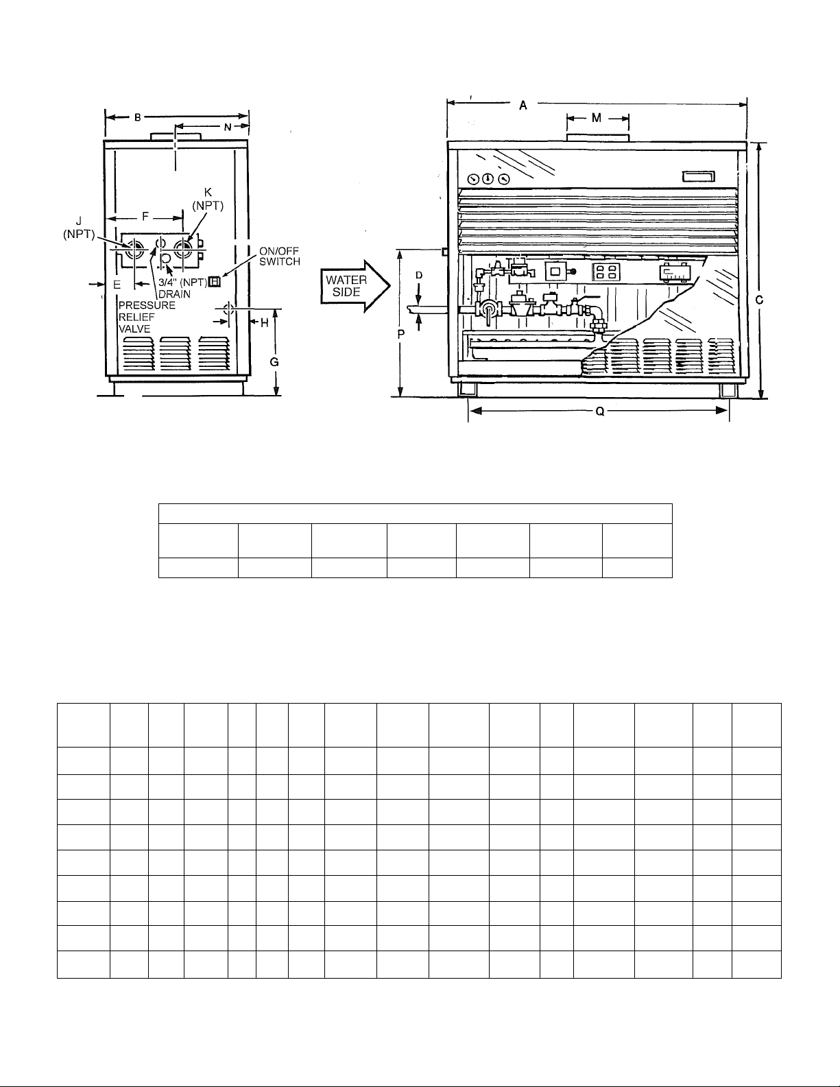
Minimum Clearances To Combustibles In Inches (MM)
Water
Top
Side
All Models 12" (305) 12" (305)
Blank
Side
Rear
6" (152) 6" (152)
Vent Front
6" (152)
Alcove
Additional clearances for service is recommended.
ALL DIMENSIONS IN INCHES (MM)
Model A В
Width Depth
DB-720 46 1/2 29 5/8
DB-840
DB-960 57 3/4 29 5/8
DB-1080
DB-1210 581/2 32 3/4
DB-1350 641/2 32 3/4
DB-1480
DB-1610
DB-1810 82 1/2
(1184) (752)
52 3/16 29 5/8 54 3/4
(1326) (752)
(1467) (752)
52 7/8 32 3/4 58 1 1/4 7 1/2 181/2
(1343) (832) (1473)
(1486) (832)
(1638) (832)
691/2
(1765) (864) (1537)
(1905)
(2095) (864)
34
75 34
(864) (1537)
34
Cabinet
Gas
Height inlet Inlet Outlet
Water Height To Depth To Water
Water
Gas Inlet Gas Inlet inlet/Outlet Relief
C D E F
54 3/4 1 1/4 7 3/4 15 1/2 171/4
(1391) (32) (197) (394)
1 1/4
(1391) (32) (197) (394)
54 3/4 1 1/4 7 3/4 15 1/2
(1391) (32)
(32)
58 1 1/2 7 1/2 18 1/2
(1473) (38)
58 1 1/2
(1473) (38)
1 1/2
60 1/2
60 1/2 2
60 1/2 2
(1537)
(38)
(51)
(51)
15 1/2 17 1/4
7 3/4
(197) (394)
(191) (470)
(470) (472)
(191)
18 1/2 18 9/16
7 1/2
(191) (470)
71/2 18 1/2 19 1/8
(191) (470) (486)
7 1/2 181/2
(191) (470) (486)
7 1/2 18 1/2 19 1/8
(191) (470) (486)
(438) (108) (51)
(438)
171/4
(438)
18 9/16 4 21/2 1 1/4
(472)
18 9/16 4 2 1/2 1 1/4
(472)
191/8
Pressure
G H J L
41/4 2 1
4 1/4 2 1
(108)
41/4
(108) (51) (25)
(102)
(102)
4 2 1/2 1 1/4
(102)
4 1/2 2 1/2 1 1/4
(114) (64) (32)
4 1/2
(114) (64) (32)
4 1/2 2 1/2 1 1/4
(114)
(51) (25)
2 1
(64)
(64)
(64) (32)
21/2 1 1/4
(64)
(25) (305)
(32)
(32)
(32)
Flue
Depth To
Size Flue Center
M N P
12 151/2 321/2
14
(356) (419) (826)
(356)
16
(406)
16
(406)
18
(457) (438) (786)
18
(457)
(457) (349) (787)
(508)
(394)
161/2
14 16 1/2
(419)
17 1/4
(438)
171/4
(438)
171/4
13 3/4
(349)
18 13 3/4 31
20
13 3/4
(349) (787)
Height To Leg Approx.
Inlet/Outlet Width
3015/16
3015/16
30 15/16
Gas supply pressure 13.8" w.c. maximum, 5.5" w.c. minimum. Natural gas only. Electrical requirements -120 VAC; 15 Amps.
Ship.
Weight
Q
341/2 780
(826)
321/2
321/2 42 3/4 950
(826)
(786)
(786)
31
(787)
31
(876)
40 3/16
(1021) (431)
(1086)
40 7/8
(1038)
46 1/2 1,025
(1181)
521/2
(1333)
571/2
(1461)
(1600)
70 1/2
(1791) (567)
(354)
950
(431)
1,000
(454)
(465)
1,100
(499)
1,125
(510)
63
1,150
(522)
1,250
Page 3

BOILER RATE OF FLOW AND PRESSURE DROP
Head
Loss
Temp. Rise 40°F
Head
Flow
(gpm)
40 1.9 5.6 2.42 3.7
56 1.8 7.8 2.35
61 2.1 8.6
75 3.9 10.5 4.19 7.0 2.21 5.2 1.35 1810
Loss
(Feet)
Temp. Rise 10°C
Flow
(Ips)
1.0 4.2
1.5 4.9
1.4 6.2
1.6 7.0
3.0 9.3
Head
Loss
(meters)
1.16 2.8 0.56 2.1
1.89 3.2 0.76
1.62 4.2 0.81
1.96 4.7 0.98
2.91
3.55 6.2 1.85
Temp. Rise 20°F
Head
Model
Number
720
840 69 4.8
960
1080
1210 100
1350
1480 122
1610 133
1810 149 12.0
NOTE: Pressure drop shown is the loss through the boiler only and does not include any additional piping.
Flow
(gpm)
59
79
89
111
(Feet)
Temp. Rise 30°F
Head
Loss
3.5
6.8
4.5
5.3 67 2.7 50
6.8
7.9 81 3.9
9.5 89 5.0 66
Flow
(gpm)
100 6.2
(Feet)
40 1.7 3o
46 2.1 35
53 3.3
59 2.1 45
74 3.2
Temp. Rise 15°C
Head
Flow
(Ips)
5.2
5.7
Loss
(meters)
1.15
1.26 3.9 0.73 1350
1.49
Temp. Rise 20°C
Head
Flow
(Ips)
2.4 0.58 840
2.8 0.69 960
3.1 0.51 1080
3.5 0.64 1210
4.3 0.84 1480
4.7 1.10 1610
Loss
(meters)
0.36 720
Model
Number
SUGGESTED SPECIFICATIONS
Hydronic boiler shall be A. O. Smith Dura-Max model DB with an input rating of BTU/Hr (KW) and having an
output rating of BTU/Hr (KW). The boiler shall be design certified by the American and Canadian Gas Associations and
shall carry the ASME “H" Symbol. The wet section shall be design registered in accordance with the requirements of the ASME
Code and shall carry an appropriate National Board Number or Canadian Registration Number. All internal waterways shall be
copper, brass or bronze. The heat exchanger shall be a two (2) pass design incorporating integral fin copper tubes. The double
row heat exchanger shall have staggered tubes. Cast bronze return bends shall be readily removable to permit visual inspection
or cleaning without removing the entire wet section assembly. Silicone “O" ring gaskets shall form a water tight seal by compres
sion and shall be isolated from the flue gasses by 3/4" (2cm) board type ceramic fiber insulation. The heat exchanger assembly
shall be hydrostatically tested to a pressure of 240 psi (1655 kPa) and shall have a maximum working pressure of 160 psi (1100
kPa).
The Combustion Chamber shall be constructed of board type ceramic fiber insulation rated to 2300“F (1260“C) which interlock to
form a gas tight seal and shall be supported in a heavy gauge corrugated steel frame. The external cabinet shall incorporate a
built-in draft hood and shall be of baked enamel steel construction. It shall be suitable for installation on combustible flooring. The
burners shall be a stainless steel stamped design and shall be mounted in a removable drawer assembly.
The burner controls shall be 24 VAC and shall include slow opening main gas valve for soft ignition, redundant safety shutoff gas
valve, main and pilot pressure regulators, recycling intermittent pilot system with one second shutdown in the event of pilot flame
failure, automatic recycling high limit, manual reset ECO limit, main and pilot manual cocks, manual firing valve, an ASME rated
pressure relief valve and factory installed flow switch.
The boiler shall comply with the latest edition of ASHRAE/IES 90.lb-1989 (1992 requirements) Standards. Optional: Factory
installed dial-type temperature and pressure gauges shall be mounted on the front of the cabinet.
Page 4

VENT
TERMINAL
Dura-Max Side Wall Venting
Side Wall Vent Hoods
Part
Number
6526 11-1/2"
6526-1
Dimensions in Inches (mm)
A B C
(290mm)8"(203mm)
11-1/2"
(290mm)
Side View
Power Venter Dimensions
Part
Number
6551-1 8"
6551-2 10"
Dimensions in Inches (mm)
A B C
(203mm)
(254mm)
10"
(254mm)
14-3/4"
(375mm)
' 18"
(457mm)
20"
(508mm)
20"
(508mm)
15-1/4"
(387 mm)
16-1/2"
(419 mm)
Elbow 90 Degree 10' (3m)
Elbow 45 Degree 5' (1.5m)
Dimensions in inches (Miilimeters)
Power
Draft Hood
Model
DB-720
DB-840 14" (356mm) 6551-1 6526
DB-960
DB-1080 16" (406mm)
DB-1210 16" (406mm)
DB-1350 18" (457mm)
DB-1480
DB-1610 18" (457mm)
DB-1810 20" (508mm)
N/R = Not Recommended
Outlet Size
12" (305mm)
14" (356mm) 6551-1
18" (457mm)
A.O. Smith Water Products Co., Inc. On Line
Venter
Part #
6551-1 6526
6551-1 6526
6551-2
6551-2 6526-1
6551-2
6551-2
6551-2 6526-1
www.hotwater.com
For Technicallnformation
Phone: 800-265-8520
Side Wall
Vent Hood
Part#
6526
6526-1
6526-1
6526-1 N/R
Equivalent Length
Vent Length
(Maximum
Equivalent
Feet of
Pipe)
Vent Pipe Size
6" (152mm) 8" (203 mm) 10" (254mm) 12" (305mm) 14" (356mm)
100' (30.5m) N/R N/R N/R N/R
80' (24.4m) 100' (30.5m) N/R N/R N/R
50' (15.25m)
NR 40' (12m)'
N/R 100' (30.5m) N/R N/R
N/R
N/R 100' (30.5m) N/R N/R
N/R N/R
100' (30.5m)
100' (30.5m) N/R N/R
80' (24.4m) 100' (30.5m) N/R
A. O. Smith Enterprises Ltd.
Water Products Company
A Subsidiary of A. O. Smith Corporation
Stratford, Ontario
A. O. Smith Corporation reserves the right to make product changes
or improvements at any time without notice.
N/R
100' (30.5m)
30' (9m) 70' (21.3m)
N/R N/R
N/R N/R
N/R
N/R
N/R
N/R
100' (30.5m)
Ei Paso, Texas
McBee, South Caroiina
Seattie, Washington
Veidhoven, The Netheriands
 Loading...