

Page 1
®
Hydronic Heating Boilers
UP TO 82% EFFICIENT H Y DRONI C HEATING BOILERS
MODELS
DB-720
through
The Dura-Max® series offers excellent performance and low-profi le design fl exibility for
both new construction and retrofi t applications. A double-row, integral-fi nned copper
tube heat exchanger provides exceptional heat transfer effi ciency. Each unit features a
small footprint with a built-in draft diverter for extra clearance to simplify installation.
Reliable, quiet, drawer-mounted stainless steel burners resist corrosion, improve
access for easy maintenance.
FEATURES
100% ALL NON-FERROUS HEAT EXCHANGER WATERWAYS
■
All waterways 100% copper, brass or bronze
■
Won’t rust, resists thermal shock
■
Heavy-duty bronze castings and copper heat exchange tubes
■
Bronze removable return bends for easy access and inspection
of individual tubes
GASKETLESS WET SECTION
■
Unique “O”-ring design compresses to form water-tight seal
positioned away from and outside the combustion chamber
■
Isolated location offers optimum protection and years of service
DRAWER-MOUNTED, STAINLESS STEEL DURA-MAX® BURNERS
■
Quiet operation and effi cient, reliable design
■
Protects against corrosion and condensation deterioration
■
Easy slide-out burner tray simplifi es cleaning and maintenance
DB- 1810
COMPACT, LOW-PROFILE DESIGN
■
Built-in draft diverter provides extra clearance in tight, retrofi t installations
■
Clean, compact jacket design for easy access and assembly
■
Cool to touch and approved for combustible fl oors
INTERMITTENT ELECTRONIC IGNITION
■
Eliminates standing pilot, saves energy
■
Includes power ON/OFF switch
CODE COMPLIANCE
■
Meets or exceeds the thermal effi ciency and standby loss requirements
of the U.S. Department of Energy and current edition of ASHRAE/IESNA 90.1
TEN-YEAR HEAT EXCHANGER LIMITED WARRANTY
■
For complete information, consult written warranty or contact A. O. Smith
June 2011R
Low Lead Content
Page 1 of 4
AOSHG30300
Page 2
®
Hydronic Heating Boilers
OTHER DURA-MAX® FEA TURES
MANUAL RESET, HIGH LIMIT
SAFETY FLOW SWITCH
ASME-RATED PRESSURE RELIEF VALVE 50#
REDUNDANT GAS VALVE
DURA-MAX® OPTIONS
CSD-1
CALIFORNIA CODE
THERMAL BALANCER PUMP DELAY
PANEL MOUNTED INLET/OUTLET DIAL
THERMOMETERS AND PRESSURE GAUGE
MODULATING FIRING
DUAL STAGE FIRING
RIGHT END GAS AND/OR WATER CONNECTIONS
CUPRO-NICKEL HEAT EXCHANGER
SIDEWALL VENT KITS
LOW WATER CUTOFF
STANDARD MODELS
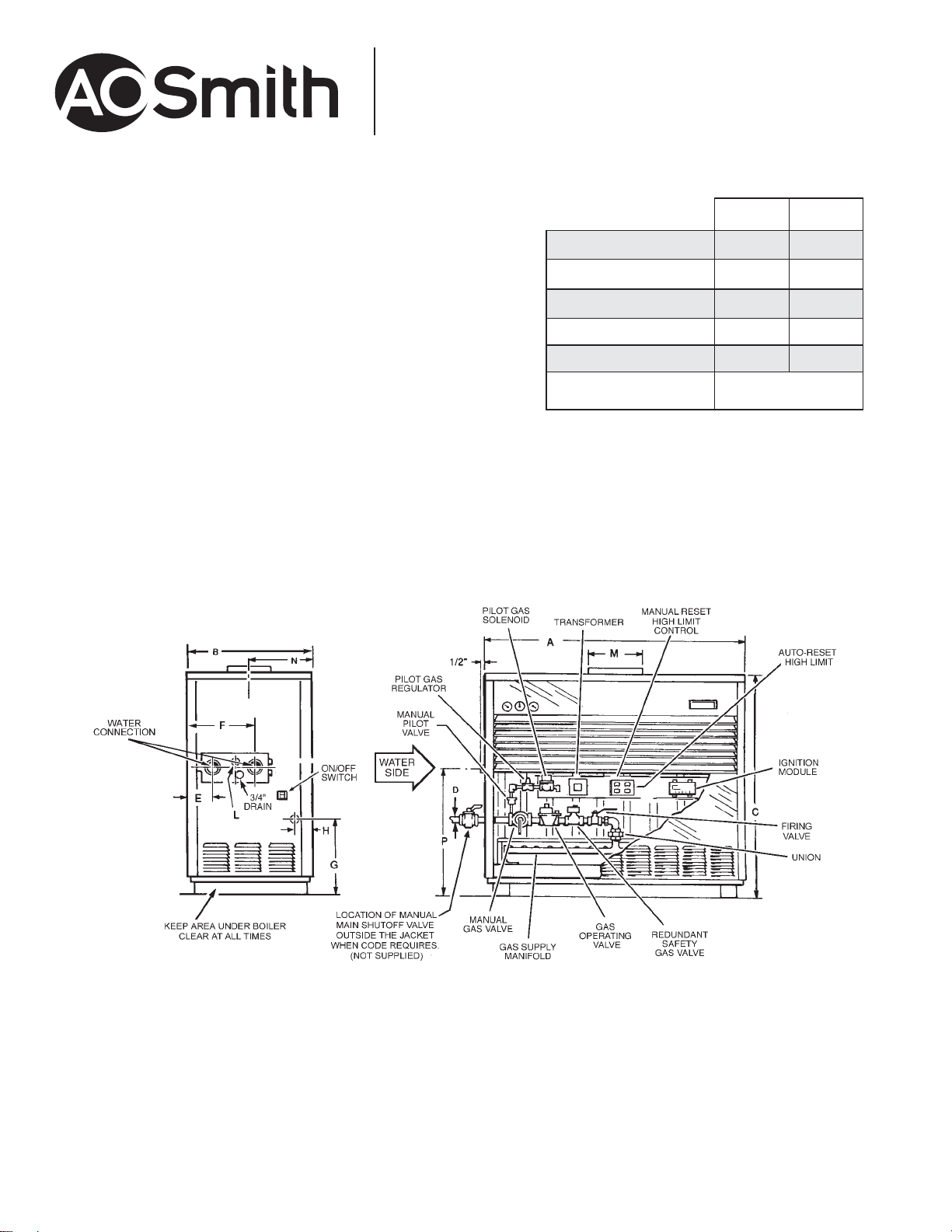
MINIMUM CLEARANCES TO COMBUSTIBLES ALL MODELS
Inches CM
TOP 12
WATERSIDE
BLANK SIDE
REAR
VENT
FRONT
* Natural gas only
Gas supply pressure: 13:8” w.c. maximum, 5.5” w.c. minimum
Electrical requirements: 120 VAC, 15 Amps
18
6
6
6
30.5
45.7
15.5
15.5
15.5
Alcove
June 2011R
www.hotwater.com
Page 2 of 4
AOSHG30300
Page 3

®
Hydronic Heating Boilers
INPUT/OUTPUT, FLOW RATE (GALLONS AND LITRES PER MINUTE) AND PRESSURE DROP
20°F/11°C DELTA T 30°F/17°C DELTA T 40°F/22°C DELTA T
MODEL
NUMBER
DB-720
DB-840
DB-960
DB-1080
DB-1210
DB-1350
DB-1480
DB-1610
DB-1810
Pressure drop shown is loss through boiler only, and does not include any additional piping.
BTU/HR.
INPUT
720,000
840,000
960,000 777,600
1,080,000
1,210,000
1,350,000 1,107,000
1,480,000
1,610,000
1,810,000
BTU/HR.
OUTPUT
583,200
680,400
885,600
992,200
1,184,000
1,288,000
1,448,000
MAXIMUM FLOW
GPM LPM
59 223 3.5 1.1 39 149 1.7 0.5 29 111 1.0 0.3
69 260 4.8 1.5 46 173 2.1 0.6 34 130 1.5 0.5
79 297 6.8 2.1 52 198 3.3 1.0 39 149 1.9 0.6
89 339 4.5 1.4 60 226 2.1 0.6 45 169 1.4 0.4
100 379 5.3 1.6 67 253 2.7 0.8 50 190 1.6 0.5
112 423 6.8 2.1 75 282 3.2 1.0 56 212 1.8 0.5
120 453 7.9 2.4 80 302 3.9 1.2 60 226 2.1 0.6
130 492 9.5 2.9 87 328 5.0 1.5 65 246 3.0 0.9
146 554
PRESSURE DROP
FEET
METERS
12.0
3.7 98 369 6.2 1.9 73 277 3.9 1.2
MAXIMUM FLOW
GPM LPM
PRESSURE DROP
FEET
METERS
DIMENSIONS AND SHIPPING WEIGHTS
MAXIMUM FLOW
GPM LPM
PRESSURE DROP
FEET
METERS
MODEL
NUMBER
DB-720
DB-840
DB-960
DB-1080
DB-1210
DB-1350
DB-1480
DB-1610
DB-1810
Water connections on DB-720 through DB-960: 2”
Water connections on DB-1080 through DB-1810: 2-1/2”
INCHES OR
CM
Inches
CM
Inches
CM
Inches
CM
Inches
CM
Inches
CM
Inches
CM
Inches
CM
Inches
CM
Inches
CM
ABCDEFGHLMNP
46-1/2 29-5/8 54-3/4 1-1/4 7-3/4 15-1/2 17-1/4 4-1/4 1 12 15-1/2 32-1/8
118.1 75.2 139.1 3.2 19.7 39.4 43.8 10.8 2.5 30.5 39.4 81.6
52-1/5 29-5/8 54-3/4 1-1/4 7-3/4 15-1/2 17-1/4 4-1/4 1 14 16-1/2 31-1/8
132.6 75.2 139.1 3.2 19.7 39.4 43.8 10.8 2.5 35.6 41.9 79.1 431 Kg
57-3/4 29-5/8 54-3/4 1-1/4 7-3/4 15-1/2 17-1/4 4-1/4 1 14 16-1/2 32-1/8
146.7 75.2 139.1 3.2 19.7 39.4 43.8 10.8 2.5 35.6 41.9 81.6
52-7/8 32-3/4 58 1-1/4 7-1/2 18-1/2 18-9/16 4 1-1/4 16 17-1/4 30-15/16
134.3 83.2 147.3 3.2 19.1 47 47.1 10.2 3.2 40.6 43.8 78.6
58-1/2 32-3/4 58 1-1/2 7-1/2 18-1/2 18-9/16 4 1-1/4 16 17-1/4 30-15/16
148.6 83.2 147.3 3.8 19.1 47 47.1 10.2 3.2 40.6 43.8 78.6
64-1/2 32-3/4 58 1-1/2 7-1/2 18-1/2 18-9/16 4 1-1/4 18 17 1/4 30-15/16
163.8 83.2 147.3 3.8 19.1 47 47.1 10.2 3.2 45.7 45.7 78.6
69-1/2 34 60-1/2 1-1/2 7-1/2 18-1/2 19-1/8 4-1/2 1-1/4 18 13-3/4 31
176.5 86.4 153.7 3.8 19.1 47 48.6 11.4 3.2 45.7 34.9 78.7
75 34 60-1/2 2 7-1/2 18-1/2 19-1/8 4-1/2 1-1/4 18 13-3/4 31
190.5 86.4 153.7 5.1 19.1 47 48.6 11.4 3.2 45.7 34.9 78.7
82-1/2 34 60-1/2 2 7-1/2 18-1/2 19-1/8 4-1/2 1-1/4 20 13-3/4 31
209.6 86.4 153.7 5.1 19.1 47 48.6 11.4 3.2 50.8 34.9 78.7
DIMENSIONS
SHIPPING
WEIGHT
780 Lbs.
354 Kg
950 Lbs.
950 Lbs.
431 Kg
1000 Lbs.
454 Kg
1075 Lbs.
488 Kg
1100 Lbs.
499 Kg
1125 Lbs.
510 Kg
1150 Lbs.
522 Kg
1250 Lbs.
567 Kg
June 2011R
www.hotwater.com
Page 3 of 4
AOSHG30300
Page 4

®
Hydronic Heating Boilers
SUGGESTED SPECIFICATION
The hydronic heating boiler(s) shall be A. O. Smith Dura-Max® model DB ______ with an input rating of ______ BTU/hr and a recovery rating of ________________ BTU/hr at
100°F temperature rise. The boiler(s) shall be design-tested and certified to the ANSI Z21.13 – CSA 4.9 Standards and shall carry the ASME “H” Symbol. The wet section shall be
design-registered in accordance with the requirements of the ASME Code and shall carry an appropriate National Board Number or Canadian Registration Number. All waterways
shall be copper, brass or bronze. The heat exchanger shall be a two (2)-pass design incorporating integral-finned copper tubes . The double-row heat exchanger shall have staggered
tubes. Cast bronze return bends shall be readily removable to permit visual inspection or cleaning without removing the entire wet section assembly. Silicone “O”-ring gaskets shall
form a water-tight seal by compression and shall be isolated from the flue gases by 3/4” board-type ceramic fiber insulation. The heat exchanger assembly shall be hydrostatically
tested to a pressure of 240 psi (1655 kPa) and shall have a maximum working pressure of 160 psi (1100 kPa).The combustion chamber shall be constructed of board-type ceramic
fiber insulation rated to 2300°F (1260°C) which interlocks to form a gas-tight seal and shall be supported in a heavy-gauge corrugated steel frame. The external cabinet shall
incorporate a built-in draft hood and shall be of baked enamel steel construction. It shall be suitable for installation on combustible flooring. The burners shall be a stainless
steel stamped design and shall be mounted in a removable drawer assembly.The burner controls shall be 24 VAC and shall include slow-opening main gas valve for soft ignition,
redundant safety shutoff gas valve, main and pilot pressure regulators, recycling intermittent pilot system with one-second shutdown in the event of pilot flame failure, automatic
recycling high limit, manual reset ECO limit, main and pilot manual cocks and manual firing valve, and an ASME-rated pressure relief valve. The boiler shall be approved by Factory
Mutual (FM).The boiler shall meet or exceed the thermal efficiency and standby loss requirements of the U.S. Department of Energy and current edition of ASHRAE/IESNA 90.1.
For Technical Information and Automated Fax Service, call 800-527-1953. A. O. Smith Corporation reserves the right to make product changes or improvements without prior notice.
June 2011R
www.hotwater.com
Page 4 of 4
AOSHG30300
 Loading...