


AR8200

Section 5, 5-1
(5) Memory channels & banks
It is convenient to store commonly used frequencies into a memory channel along with mode etc, this
saves having to key the data in over and over again. Memory read is very straightforward and quick
when compared to re-typing all data.
5-1 Memory channel overview
Think of memory channels as pages in a notebook each of which is numbered to identify it. Data may be
written to each new page (memory channel) and each page may be overwritten with new data, they can
be used over and over again. The AR8200 has 1,000 memory channels in addition to 10 ‘quick
memory’ channels and a priority channel.
Each memory channel may hold:
l
one frequency
l
receive mode
l
tuning step
l
step-adjust
l
frequency offset
l
attenuator setting
l
noise limiter status
l
AFC status
l
pass status
l
write protect
l
text comment of up to 12 characters
The alphanumeric comment may be used to ease identification at a later date and to provide text search
facilities.
The 1,000 memory channels are divided into 20 banks, each initially having 50 channels. The memory
banks are identified by letters A, B, C, D, E, F, G, H, I, J (upper case letters) and a, b, c, d, e, f, g, h, i, j
(lower case letters) and initially numbered from 00 to 49.
Examples are “A00” for the first channel location in memory bank “A” and “A49” for the last memory
channel in memory bank “A”. “e15” is the location of memory bank “e” (lower case) channel “15”.
During the manufacture and testing of the receiver, various test frequencies may be entered into the
receiver’s memory banks so the memory locations may not be completely blank.
&Note: Where memory channels and banks are empty the indication “- - -” is often displayed.
The stored data may be quickly and easily recalled, changed or deleted using the memory recall, edit
and delete facilities.
&Note:
to make the recalling and scrolling of memory banks fluent, if no data is stored, the
AR8200 may take up to 5 or 6 seconds to respond when attempting to change memory
bank while the CPU checks for data.
It is suggested that one or two frequencies be held in each memory bank
51
Section 5-1, 5-2
Auto-store
When shipped from the factory, memory bank “J” is reserved for auto-store of memory channels
from search mode. This is a useful facility to quickly build a list of active frequencies. Please refer
to
section 8-7-5
Dynamic memory bank resizing
The lettered memory banks are regarded as a ‘pair’ making a total of 100 memory channels per bank,
initially equally divided between the upper and lower case letters. It is however possible to reallocate the
100 channels in blocks of 10 channels between the same letters A/a, B/b, C,c etc This means that the
initial 50/50 may be reallocated as 60/40, 70/30, 80/20, 90/10, or 10/90, 20/80, 30/70, 40/60. This
‘dynamic’ memory reallocation can be useful to optimise the memory layout where a large or small
collection of frequencies need to be monitored without unnecessarily wasting memory banks with just a
few channels occupied.
Write protect
It is possible to write protect individual memory channels to prevent accidental deletion, whole memory
banks and a ‘global’ write protect facility are also available.
Memory backup
The data contents of memory and search banks are held in an flash-ROM so that no backup battery or
capacitor is required for memory retention.
of this manual for further information regarding AUTO-STORE.
&Note: When the AR8200 is switched OFF, all VFO data will be automatically stored.
Should the NiCads (or dry batteries if in use) become completely exhausted, the last stored
memory channel or last VFO data ‘may’ be lost if the AR8200 is not powered-down using the
key and insufficient power is available to save the data.
5-2 Storing VFO frequencies & data into memory
It is possible to save frequencies to the ten quick memories for simple recalling but for longer-term
storage, the 1,000 main memory channels offer a better and more flexible system.
The process to save a displayed VFO frequency to memory is as follows:
a) In VFO mode, select the required frequency, mode, attenuator etc
b) to initiate memory write
c) Use the keypad, main dial or ïðñò keys to select the desired memory location
(BANK and CHANNEL)
d) Add a text comment (optional) or delete an existing comment
e) Add memory channel write protect (optional)
f) Exit the menu to save the data to the specified memory location
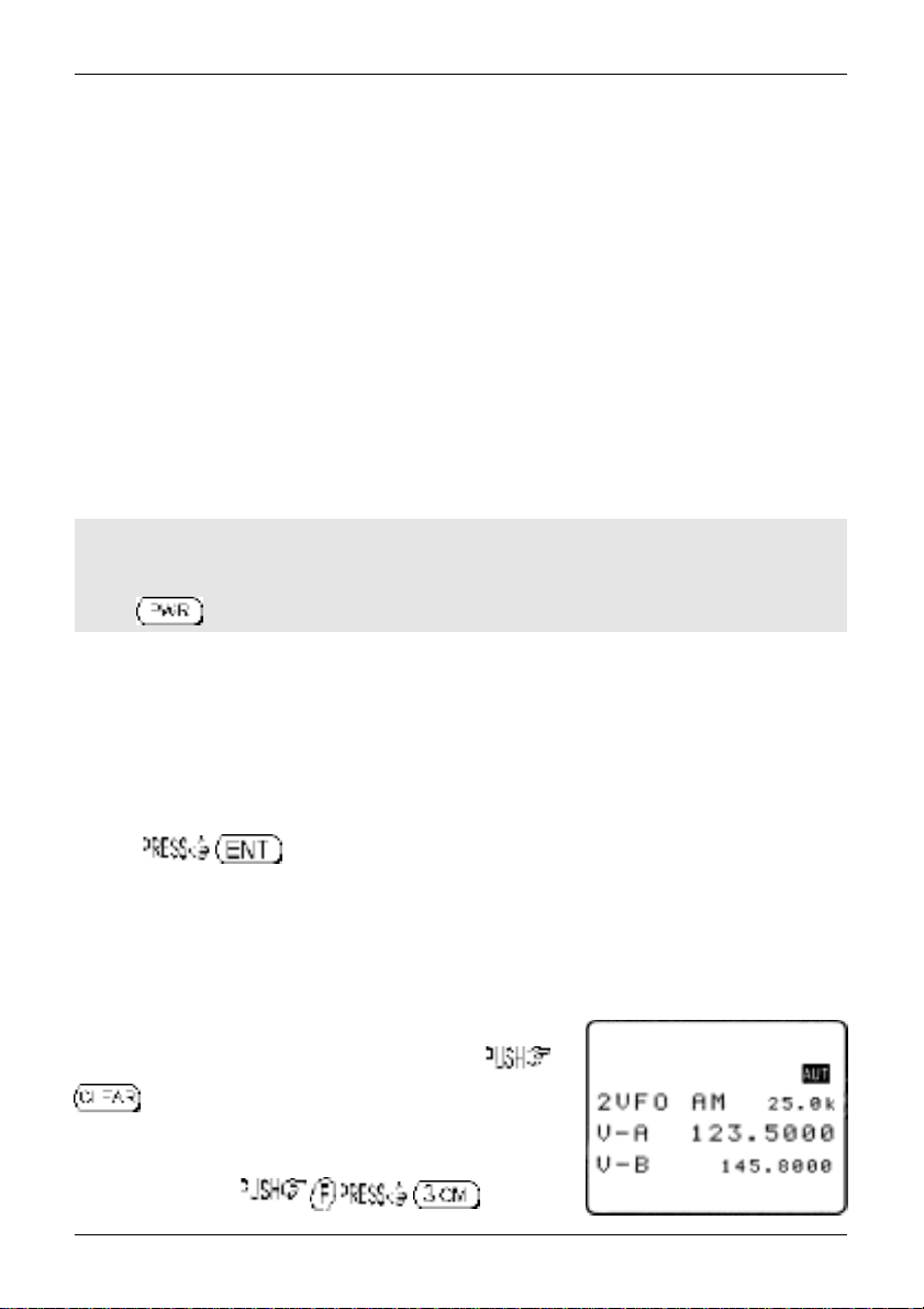
Lets assume that you wish to store the frequency of 123.500 MHz
(with the attenuator off, noise limiter off, AFC off) into memory bank
“E” location “25” (E25) while in VFO mode with the text comment of
“AIRBAND”. If a mistake is made during programming, the
key to abort entry and return to 2VFO mode.
a)
Start by selecting VFO mode then key in the frequency of 123.500
MHz, “mode and step size” are set to the default auto “AUT” (if not
use the key sequence )
52
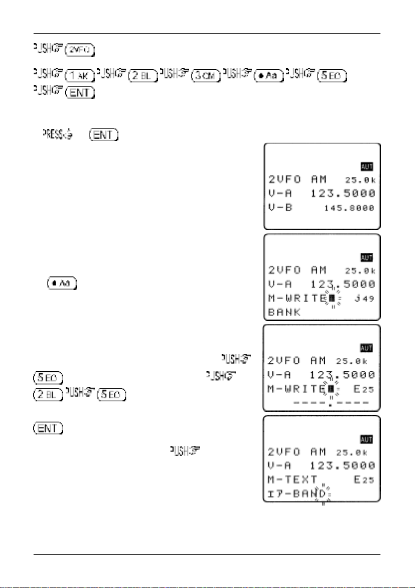
to place the AR8200 into VFO mode.
to select the desired frequency, the mode and step size will be automatically set by
the AR8200 microprocessor.
b)
the key for more than one second to enter ‘memory input’ mode.
One line up from the bottom of the LCD will be the legend
“M-WRITE” with the highlight cursor positioned to the left of the
bank identification letter such as “j”. The microprocessor will
automatically select the youngest free memory location.
c)
You may change the bank identifier at this time by pushing the
ï ð keys or by typing in a three digit memory location using the
numeric keypad.
You will notice that to the right of the keypad numbers, there are
small orange letters which are bank identifiers, available memory
locations are A - J and a - j. Key 1 is “A”, key 2 is “B” etc, ignore
the letters K - T as these are used in search mode only. The lower
case bank identifiers may be accessed pushing the CASE SHIFT
key
Remember, if you take too long entering data (90 seconds)
the display will revert to it’s original condition of 2VFO mode,
if you are selecting the memory location via a three digit
key sequence, you only have 2 seconds before the keypad
times-out!
Section 5-2
Assuming that you wish to store 123.500 MHz into “E25”
to select bank “E” then select the channel,
for “25”. If any data is already stored
in location “E25”, the bottom line of the LCD will flash with the
stored frequency. You may accept & store the data (by pushing
or add a text comment at this point (see below).
d)
To add the text comment “AIRBAND”, ò then use the
main dial to select the text and the ï ð keys to move position of
text input.
A maximum of 12 characters may be added to each memory
channel, it is recommended that a minimum of three be used for
efficient use of the text search feature (a minimum of 2 characters
are required for text search). Refer to
details of text search and
section 13-2
section 12
for short cut text input).
of this manual for
53
Section 5-2, 5-2-1
If the memory location has been used previously and a text comment is displayed, to
delete the existing comment.
&Note: It is possible to use keypad short cuts to select text characters, please refer to
section 13-2
You may accept the new frequency and text comment “AIRBAND” by pushing or you may add
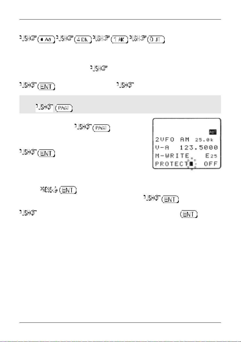
memory channel write protect (see below).
e)
To add the memory channel write protect, ò to access the “PROTECT” menu, the default is
off. to toggle the status to “ON”.
To accept the input and store the data to the specified location, . The display will
revert to 2VFO mode.
of this manual for further details.
&Important note: It is suggested that you do not use the write protect facility until you are
familiar with the operation of the AR8200 as it will prevent certain functions being carried out
at a future time.
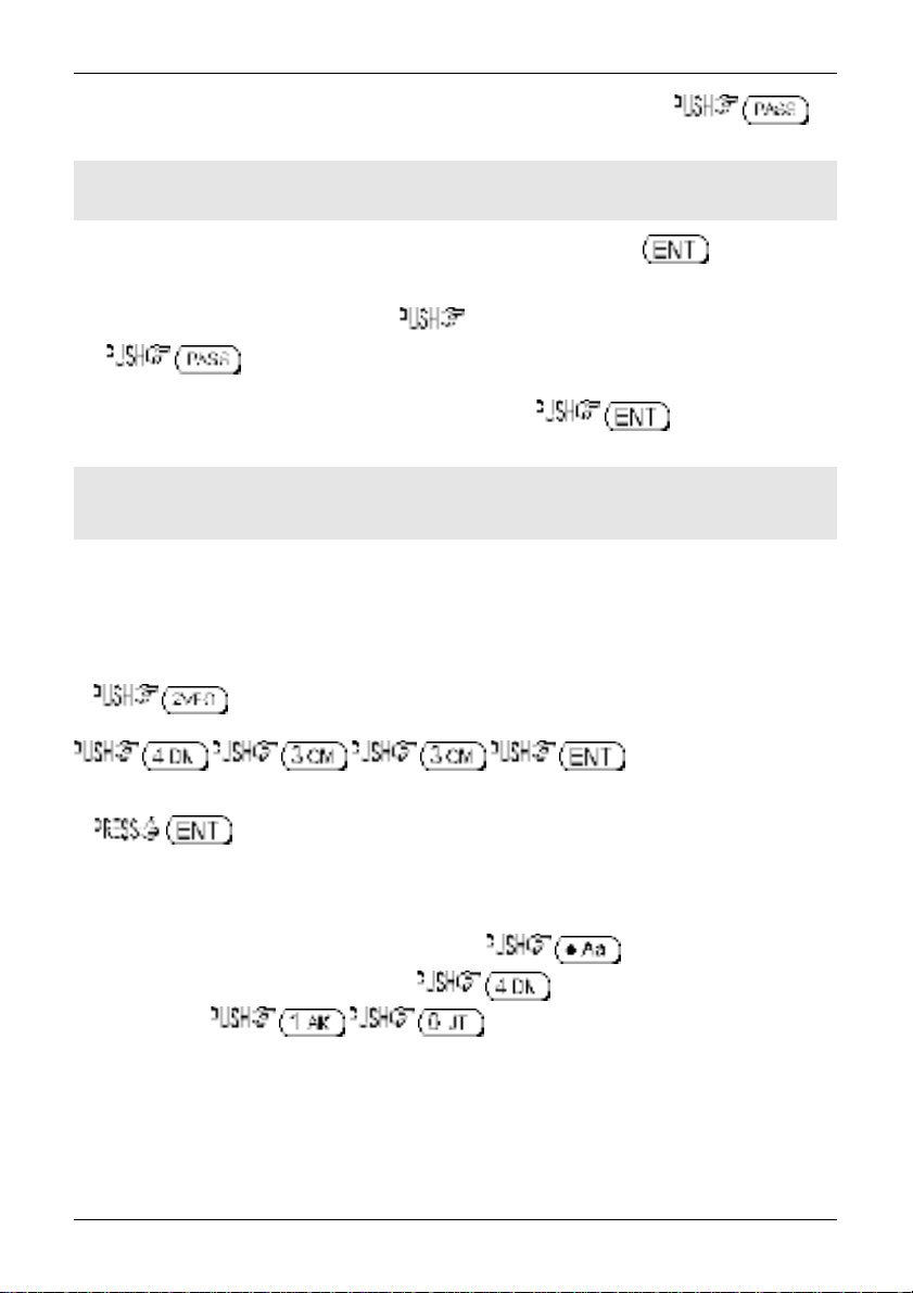
5-2-1 Another example of memory write
Let’s assume that you wish to store the frequency of 433.000 MHz auto-mode into memory location
“d10” with the text comment of “70cm”.
a)
to place the AR8200 into VFO mode
to select the desired
frequency.
b)
to initiate ‘memory input’ mode.
c)
Select the bank by pushing the ï ð keys and using the main dial for channel number, or by typing in
a three character memory address using the numeric keypad.
Assuming that you wish to store 433.000 MHz into “d10” which acts as the CASE
SHIFT key to select the lower case banks then to select bank lower case “d”. Next
select the channel for “10”. If any data is already stored in location
“d10”, the bottom line of the LCD will flash with the stored frequency.
You need to carry out this key sequence fluently within 2 seconds or the bank location will time out.
The 2 second time out does not apply when the bank and channel are selected using the main dial
and ï ð keys.
54
Section 5-2-1, 5-2-2, 5-3
To recap:
Once the three digit memory location has been selected, the 2 second keypad time-out does not apply to
the rest of the sequence.
d)
To add the text comment “70cm”, ò then use the main dial to select the text and the
ï ð keys to move position of text input. To accept the new frequency and text comment “70cm”,
, if you wish to add write protect ò to access the PROTECT menu.
&Note: If the memory location has been previously used and a text comment is displayed,
to delete the existing comment.
e)
In the write protect menu, to toggle the status
to “ON”, the default is off.
To accept the input and store the data to the specified location,
. The display will revert to 2VFO mode.
5-2-2 Automatic memory allocation
When you to start the memory write sequence, the AR8200 will initially offer the first
available empty memory location which has no data stored in it. to accept the
channel offered or choose another location as described in the previous sections. Alternatively you may
the ò key to add a text comment then complete memory write by pushing . If the
AR8200 has to look through many full memory channels before an empty channel is located, the
message “MEM WRITE SEARCH BLANK CH” may be briefly displayed.
5-3 Memory write protect
As indicated in
memory channels are not accidentally over-written. It is important to remember that by write protecting a
memory channel, it may prevent certain facilities from being used (such as over-writing the memory
channel or copying / swapping memory data to it).
The memory protect status may be assigned as the last stage of memory write (as per
manual) or toggled on/off using the memory channel EDIT facility, refer to
regarding memory channel EDIT facilities, in particular MEMORY PROTECT.
It is also possible to write protect a whole memory bank, this prevents accidental deletion of data when
resizing memory banks.
section 5-2
, it is possible to write protect memory contents to ensure that important
section 9-6
section 5-2
of this manual
of this
55
Section 5-3, 5-4
The memory bank write protect may be toggled on/off using the SCAN environment menu accessed by
the key sequence followed by four pushes of the ò key. the
to toggle bank select on/off and to accept the changes and exit the menu.
Please refer to
section 7-8-6
of this manual for details on MEMORY BANK write PROTECT.
&Note: Memory channel write protect prevents accidental over-writing and deletion of specific
memory channels but does not prevent loss of data due to memory resizing or when using the
optional external memory slot card.
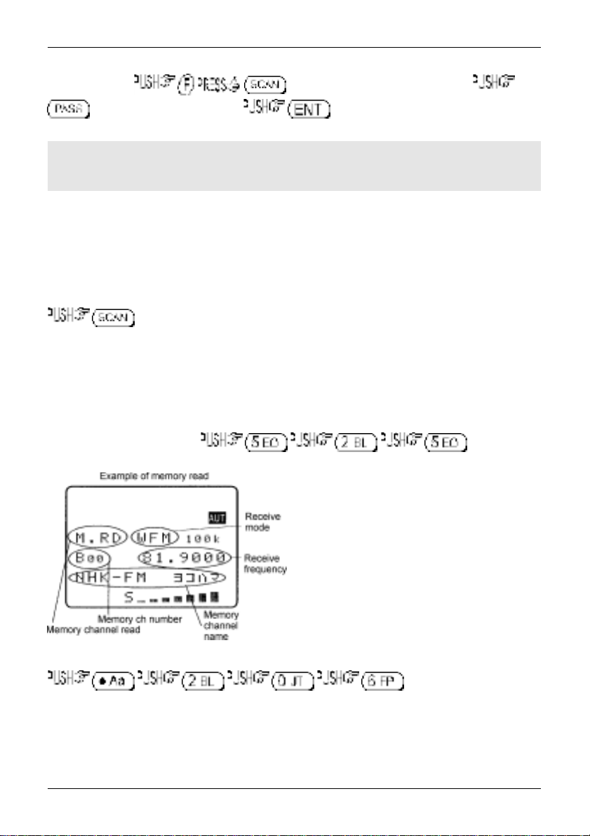
5-4 Memory read “M.RD”
Once frequency and mode data has been stored into a memory location, its retrieval is quick and simple.
Let’s assume that you wish to retrieve the frequency of 123.500 MHz which has been programmed into
to memory “E25” during an earlier example in the preceding
to place the receiver into memory read mode, the legend “M.RD” appears toward the
top left of the LCD to confirm operation. The AR8200 will monitor whatever memory channel first appears
when you enter memory read.
The AR8200 will display memory channel, mode, frequency, tuning step, text comment (if one was used),
attenuator status, noise limiter status and AFC status. The memory channel last used (for memory write
or recall) will initially be displayed, If the desired memory channel is not immediately displayed it may be
recalled by keying in the required three digit location.
section 5-2
of this manual.
To recall memory channel “E25”
(there is no need to push enter).
The “BANK/CH SEL” legend automatically appears
when the first key is pushed to remind you that you
are recalling memory channels in memory read
mode. Keypad memory recall requires a three digit
location, one letter for the bank and two numbers for
the channel. If you hesitate for more that 2 seconds
while recalling memory channels via the keypad the
sequence will time out, for more leisurely memory
recall use the ï ð ñ ò keys.
To recall memory “b06” the CASE SHIFT key needs to be used to access the lower case bank,
(there is no need to push
enter). If you attempt to recall a memory which has no valid data (because it is blank) the next valid
memory channel will be displayed instead. Blank memory channels are ignored.
56
Section 5-4-1, 5-5
5-4-1 Memory channel review / hunt
From VFO mode to enter memory read “M.RD” mode.
The main dial may be rotated or the ñ ò keys pushed to review, hunt for and select memory channels
one by one, channels with no data stored will be skipped. the ï ð keys to move between
memory banks one by one.
&Important note: It is suggested that each memory bank be programmed with at least one
memory channel otherwise the AR8200 may appear
as the CPU has to check all memory channels for valid data, this is particularly noticeable if
jumping between bank “A” and “j” (opposite ends of the AR8200 memory map).
slow or sluggish
when recalling banks
Memory read using the main dial and ï ð ñ ò keys is useful for reviewing memory contents and
hunting for a specific channel if you forget where you stored it! Should you know the number of the
required memory channel, the keypad method of memory recall will be much faster. The AR8200 will
monitor whichever memory channel is displayed in memory read “M.RD” mode.
It is also possible to hunt for memory channels using the TEXT SEARCH facility, please refer to
section 12-2 of this manual for further details.
5-5 Deleting memory channels
It is possible to over-write a memory channel with new data, edit the contents of a memory channel or
delete the channel entirely. When in memory read mode, use the key sequence
to access the “MEM DELETE” menu. The LCD menu invites you to “PUSH ENTER”
to delete the current memory channel, to delete it or to abort.
When deleted, the AR8200 increments to the next memory channel which contains data. It is also
possible to delete whole memory banks in one go using the DELETE menu. Please refer to the
section 10-3
of this manual relating to memory bank DELETE options.
57
Section 5-5-1, 5-5-2, 5-6, 5-7
5-5-1 Memory channel editing
It is possible to copy, move, swap and edit memory channels to assist the management of data.
Please refer to
section 9
of this manual regarding the EDIT menu.
5-5-2 Adding text names to memory banks
To assist with memory management and identification, memory banks can be named. The SCAN BANK
menu is used to add or edit memory bank names.
To access the SCAN BANK menu . The LCD will initially display the
legend “M-BANK”, the currently selected memory bank ‘pair’ (i.e. D/d or A/a or C/c etc) and the current
size allocation for the bank displayed i.e. B:50 b:50 for memory bank “B/b” with the allocation of 50
channels for “B” and 50 channels for “b”, this split of 50/50 being the default.
Use the main dial, ï ð keys or numeric keypad to select the required bank you wish to add a name to.
the ò key to move to the “BANK TEXT” menu.
Use the ñ ò keys to move between upper and lower bank identifiers, add text using the main dial and
ï ð keys or use the keypad. To save the data and exit the menu .
5-6 Transfer of memory channel to VFO
While in memory read, should you wish to tune away from the memory channel and benefit from not
having to re-enter the frequency, mode etc, the data may be quickly transferred from memory to ‘VFO’
mode.
To transfer memory channel data to VFO simply . The LCD will display the legend
“VFO” along with receive frequency, receive mode, tuning step size and other relevant information such
as attenuator, noise limiter and AFC status. You may monitor the frequency or tune away from it using
the main dial or ï ð ñ ò keys.
5-7 Dynamic memory bank resizing
The lettered memory banks are regarded as a ‘pair’ making a total of 100 memory channels per bank,
initially equally divided between the upper and lower case letters. For example memory bank “A” will
have 50 channels numbered from 00 to 49 (A00 - A49) and memory bank “a” will also have 50 channels
numbered from 00 to 49 (a00 - a49) making a total of 100 channels.
It is possible to reallocate the 100 channels in blocks of 10 channels between the same letters A/a, B/b,
C,c etc This means that the initial 50/50 may be reallocated as 60/40, 70/30, 80/20, 90/10, or 10/90,
20/80, 30/70, 40/60. This ‘dynamic’ memory reallocation can be useful to optimise the memory layout
where a large or small collection of frequencies need to be monitored without unnecessarily wasting
memory banks with just a few channels occupied.
The SCAN BANK menu is used to customise many features including memory bank resizing.
To access the SCAN BANK menu .
58

Section 5-7, 6
The LCD will initially display the legend “M-BANK” , the currently
selected memory bank ‘pair’ (i.e. D/d or A/a or C/c etc) and the
current size allocation for the bank displayed i.e. A:50 a:50 for
memory bank “A/a” with the allocation of 50 channels for “A” and
50 channels for “a”, this split of 50/50 being the default. Use the
main dial, ï ð keys or numeric keypad to select the required
bank for resizing. the ò key to move to the
“BANK TEXT” menu where a text comment may be added
(optionally) to ease identification of each bank (use the ñ ò keys
to move between upper and lower bank identifiers).
the ò key to move on to the resizing menu. The LCD will display the upper and lower case
identifiers on the same line with the current default allocation of 50/50 channels per bank. Use the main
dial or ï ð keys to reallocate the channels in increments of 10 channels (60/40, 70/30, 80/20, 90/10, or
10/90, 20/80, 30/70, 40/60).
&Note: If you resize a memory which currently contains 50 channels to a new size of 10
channels, the last 40 channels will be deleted and data will be lost! Potentially when you resize
memory banks, programmed data may be lost so it is suggested that you
your memory data before resizing memory channels
ignored but if a whole memory bank is protected, resizing will be inhibited.
After selecting the resizing value ò to display the memory sorting menu, the legend
“MEM SORTING” will be displayed, the following lines confirm the current and
sizes. to initiate the resizing process. The LCD will clear except for the words
“MEM SORTING !!” with the exclamation marks flashing to indicate that the sorting process is in
operation…
After sorting, the display returns to its previous condition (before the SCAN BANK menu was accessed).
this can take several minutes
depending upon the amount of data held in memory.
. Individual memory channel protect will be
carefully organise
proposed
memory bank
&Important note: Memory sorting can take several minutes, do not switch the AR8200 off,
disconnect power, remove batteries or allow the batteries to fail during memory sorting or data
corruption may occur.
(6) Priority operation
The PRIORITY feature enables you to carry on scanning, searching or monitoring while the AR8200
checks a frequency taken from one of the 1,000 memory channels (A00 default) every 5 seconds
(default) for activity.
The priority checking is accomplished by momentarily moving to the priority frequency to see if it is
‘active’. If activity is found, the receiver remains on the frequency until the signal disappears. If no
activity is detected, the receiver returns to the VFO frequency, scan channel or search bank from where it
originated. The priority facility has a large number of applications and is particularly useful for keeping an
eye on a distress frequency while scanning or searching another frequency band.
&Note: Depending upon the frequency and mode stored as priority, an audible
‘click’ may be heard when the priority facility is in operation. This is quite normal and
is caused by the internal switching of circuitry necessary to accomplish the frequency
change as two frequencies cannot simultaneously be monitored by the receiver.
59
Section 6, 6-1, 6-2
&Note: The priority mode is automatically suspended during entry of frequencies via the
keypad, this prevents the receiver from changing frequency while you are busy programming.
Priority operation is disabled when the band scope is in operation.
6-1 Engaging PRIORITY channel
Once engaged, the default channel used for PRIORITY is “A00” and the frequency contained is checked
for activity every 5 seconds.
First ensure that there is data stored in memory channel “A00”.
To engage the priority facility , this may be carried out while in SCAN,
SEARCH or VFO modes. The legend “PRI” is displayed in the top left hand corner of the LCD to indicate
that PRIORITY IS ENGAGED (switched on).
If activity is encountered on the priority channel, the AR8200 will stay on the priority frequency until the
transmission ends (and the squelch closes) after which time the priority frequency will be checked for
activity every few seconds.
&Note: Once priority has been activated, the data contents of the memory channel used
(default A00) may be altered without affecting the data used for PRIORITY operation which is
stored separately and assumes an identity of its own irrespective of the data contents of memory
A00.
Should you subsequently wish to alter the priority data, you
will have to use the “PRIO SET” menu detailed in
of this manual.
To cancel priority operation (which
acts as a toggle), the legend “PRI” will be removed from the LCD.
section 6-2-1
6-2 Changing PRIORITY channel data
The default channel used for PRIORITY is “A00” and the frequency copied from this channel is checked
for activity every 5 seconds. You may select a different memory channel from which the data will be
copied or may vary the sampling time for priority activity checking.
60

Section 6-2, 6-2-1, 6-2-2
This is accomplished by using the “PRIO SET” menu accessed by
the key sequence .
The legend “PRIO SET” appears on the top line of the LCD to
confirm selection.
6-2-1 Changing the priority channel data pickup channel
Should you wish the priority channel to use data contained in another memory location, access the
“PRIO SET” menu using the key sequence , the legend “PRIO SET”
appears on the top line of the LCD to confirm selection.
Select the new location for data pickup by the priority channel, use the main dial to move through the
memory locations one at a time or use the ï ð keys to move between banks, alternatively quickly key in
a three digit memory location via the keypad.
For example, select memory location “A23” using the key sequence
.
The priority interval time menu may be accessed using the ò key or to exit the menu.
The newly nominated channel data will be used for priority monitoring.
&Note: If you attempt to nominate a channel which contains no data, the input will be
ignored and the previously used data will continue to be employed.
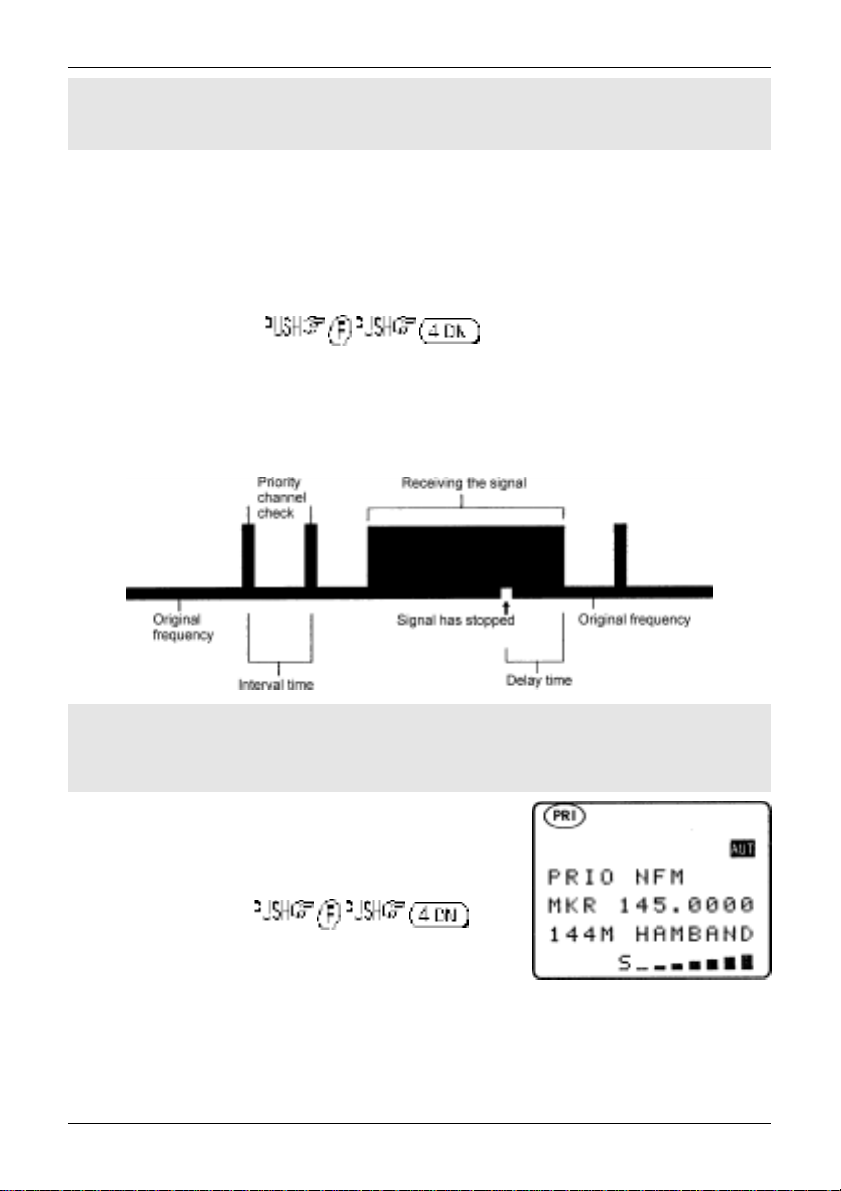
6-2-2 Changing priority interval time
Should you wish to check the priority frequency more or less often, the sampling time (interval) may be
set using the “PRIO SET” menu. Use the key sequence to access the
“PRIO SET” menu. the ò key to move the cursor to the “INTERVAL” input line.
Use the main dial to vary the interval time in increments of 1 second, the ï ð keys may be used to vary
the interval time in increment of 10 seconds. Priority time may be varied between the range of 1s to 99s.
the key to act as a short cut to 5 seconds (default).
The more often you check the priority channel, the greater chance you have of ‘catching’ activity,
however the greater the interruption to normal monitoring.
to accept the input and exit the menu.
&Note: Priority interval time is also used for VFO SCAN timings.
61

Section 7, 7-1, 7-2
(7) SCAN - scanning memory channels & banks
The AR8200 has a SCAN mode whereby the contents stored in the MEMORY CHANNELS ARE
AUTOMATICALLY RECALLED AND MONITORED very quickly for activity - scanned.
* It is important that you do not confuse SCAN and SEARCH modes. *
SEARCH mode (covered later in this manual) automatically TUNES THE RECEIVER
THROUGH ALL FREQUENCIES between two specified frequency limits
looking for active frequencies.
7-1 SCAN - outline introduction
During SCAN, the AR8200 automatically recalls each memory channel which contains data in numeric
order and monitors it looking for activity. When an ‘active’ memory channel is located (when a signal is
found and the squelch is open) the AR8200 will temporarily stop scanning.
At default when shipped from the factory, the AR8200 will remain on the active memory channel until
the received signal disappears and the squelch closes. The CPU will then wait a further 2 seconds in
case a reply is audible (such as aircraft and air traffic communications) and will then resume scanning
the memory channels again.
If the ñ ò keys are pushed or the main dial rotated (while scanning or when stopped on an active
channel), the receiver resumes scanning in the direction of the arrow key or rotation. This is particularly
useful for taking a second look a channels which have just been scanned.
Additional facilities available in SCAN
Memory banks may be “LINKED” and “UNLINKED” to effectively make larger or smaller groups of
memories which may be scanned together.
“PASS” may be used whereby memory channels can be skipped when not required (such as when
permanently busy), they may be easily reinstated at a later time.
“AUTO STORE” reserves memory bank “J” so that active frequencies found while conducting a
SEARCH may be automatically written to memory. This is a useful tool for compiling an activity list of
rarely used frequencies especially when unattended. Refer to
information relating to auto store.
It is possible to alter the sequence of scanning events using the SCAN ENVIRONMENT menu. There
are several scanning parameters which may be changed to suit your preferences and requirements
DELAY, LEVEL, VOICE, FREE & MODE, it is possible to mix combinations of all parameters.
section 8-7-5
of this manual for further
7-2 SCAN considerations
It is presumed that you have already stored your favourite and commonly used frequencies into the
memory banks (as per
A total of 1,000 memory channels are provided which are divided into 20 banks, each (at default) having
50 channels. The memory banks are identified by letters A, B, C, D, E, F, G, H, I, J (upper case letters)
and a, b, c, d, e, f, g, h, i, j (lower case letters) and numbered from 00 to 49.
section 5-2
of this manual).
62
Section 7-2, 7-3
When in SCAN MODE, the memory banks are referred to as “SCAN BANK A”, “SCAN BANK B”,
“SCAN BANK f” etc rather than using the full title “SCAN MEMORY BANK A”, “SCAN MEMORY BANK B”
etc. This terminology has been employed to make the explanation of and referral to SCAN MEMORY
BANKS (SCAN BANKS) less long-winded.
When shipped from the factory, memory bank “J” is reserved for auto-store of memory channels from
search mode so may already have frequencies stored.
Keep your memory banks tidy - for best scan speed
In order to achieve the maximum scanning speed, it is advisable to keep all similar frequencies and
modes grouped together within the memory banks. The greater the frequency change between memory
channels, then the further the receiver’s VCO (Voltage Controlled Oscillator) has to travel and the
slower the scan rates. Similarly, when many changes of mode are called, more switching has to be
accomplished and the scan speed may be reduced.
Memory channel data may be entered in duplicate into several channels. This will ensure the
channel data is scanned more frequently to increase the chances of activity being detected.
Limitations of SCAN mode
Should a number of different modes and wide range of frequencies be used, then the SCAN process
may be affected by noise or differences in squelch characteristic on some frequencies and modes.
To help provide the best operation of SCAN, additional facilities have been provided (configurable via the
SCAN ENVIRONMENT menu). Should you listen to noisy frequencies or bands containing carriers,
make liberal use of the AUDIO, LEVEL and FREE scan facilities.
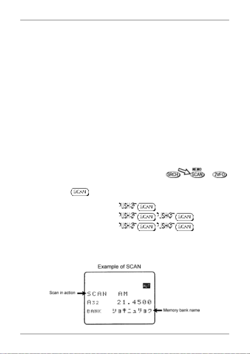
7-3 Starting to SCAN
Presuming that some memory channels are programmed with data, to start the scan process will take
one or two pushes of the key depending upon which operating mode is currently employed
(in VFO and search mode the first press accessed memory read):-
Memory read mode “M.RD”
VFO mode “VFO” or “2VFO”
Search mode “SRCH”
The legend “SCAN” is displayed toward the top left of the LCD to indicate that the SCAN process has
been started, a bank letter will also be displayed representing the current bank. Ensure that the
squelch control is advanced clockwise to threshold point so that background noise is cancelled
and the squelch closes (otherwise scan will not operate).
63
Section 7-3, 7-3-1, 7-4, 7-5
When SCAN has been selected, only the currently displayed memory bank WHICH CONTAINS DATA
will be SCANNED (as bank link is default off), receive mode and frequency are unimportant. Any
memory channels which contain no data (empty) will be ignored (skipped).
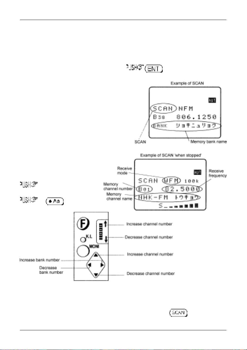
7-3-1 Transfer of active memory to VFO
When the scan process is paused on a busy channel, to transfer the current memory
frequency to VFO where it may be monitored.
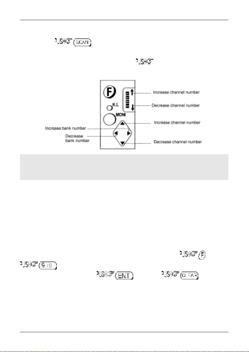
7-4 Selecting a scan bank
The memory bank identifier (such as “A”) will be
displayed on the left of the LCD under the legend
“SCAN”. If more than one memory channel is
programmed into the current memory bank the
channel numbers will be changing.
When an ‘active’ channel has been located (busy, so the
squelch opens) the scan process will
temporarily pause on the active channel, the memory
location (such as “A03”) will be displayed along with
any accompanying text (displayed underneath
the memory location).
To select another memory bank for
scanning, use the ï ð keys or
the corresponding letter on the
keypad from A to J, for lower case banks
the CASE SHIFT
key first.
If no data is available,
the next bank with
valid data will be
recalled (empty
memory banks are
skipped).
To scan more that one
memory bank at a
time, please refer to
the scan bank linking
section 7-7
manual.
of this
7-5 Channel PASS
When scanning, you may encounter active memory channels which you do not wish to currently monitor.
It is possible to manually force the scan process to continue by pressing the key or ñ ò keys
but this manual intervention can be an annoyance. For this reason it is possible to temporarily PASS
64
Section 7-5, 7-5-1, 7-5-2
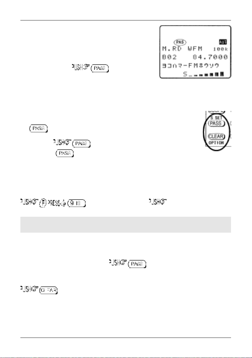
unwanted channels so that they are skipped when scanning. PASS
does not delete the memory contents but simply ‘tags’ the channel
to be skipped. In memory read, the PASS tag may toggled on/off
and the tags removed in one operation using the delete pass
channel facility of the DELETE menu.
While paused (during scan) on a busy channel which you do not
currently wish to monitor, to skip it. The scan
process will immediately move on to the next memory channel of
the current bank in the direction (up or down) which has been
previously used for tuning or memory read. This tagged memory channel will be skipped during
subsequent scans until the tag is removed. The legend “PAS” will have been assigned to the skipped
memory channel which may be reviewed in memory read mode.
7-5-1 Toggling memory channel PASS
The key may also be used to tag (skip) unwanted channels when in memory
read. To cancel channel pass tag on a particular memory channel, recall it in memory
read mode then . The LCD legend “PAS” indicates when the channel
is locked out, the key toggles “PAS” on/off.
7-5-2 Removing ALL memory PASS tags in one go
It is possible to remove the memory PASS tags of ALL memory channels in all banks in one operation
using the DELET menu.
to access the DELETE menu. the ò key six times to display
the menu option “DEL MEM PASS”.
&Note: It will take a little while for the AR8200 to look for PROTECT channels and PASS
channels as you work through the menus.
If at least one memory channel has been tagged PASS, the third line from the bottom of the LCD will
display a memory location such as “PASS-CH A17” with the “A17” simply confirming that at least one
memory channel is tagged PASS. If no memory channels have been tagged PASS, the LCD will display
“PASS-CH ---”.
To remove all memory PASS tags in one go , the legend “
be displayed to show that removal of pass tags is in process followed by “
the AR8200 checks that all tags have been removed. The LCD will then display “PASS-CH ---” to
confirm that no channels are now tagged as PASS. To exit the menu and return to the standard display
.
MEM PASS CH ALL OFF!!
MEM PASS CH SEARCH !!
” will
” as
65
Section 7-6, 7-6-1, 7-6-2, 7-7
7-6 Deleting memory channels
Although it is possible to over-write memory channels with new data, edit memory channels, swap, copy,
move and to PASS (skip) them, there will be occasions when you want to delete memory channels
completely.
7-6-1 Deleting single memory channels
While in memory read mode, to delete the currently displayed memory
channel. As a safe guard against accidental deletion you will be instructed to to
execute the deletion, alternatively to abort delete.
Once memory channels have been deleted, the data is destroyed and cannot be recalled again.
7-6-2 Deleting whole memory banks in one go
Should you wish to delete the entire contents of a memory bank, the DELETE menu may be used, this is
quicker than recalling each memory in memory read mode and deleting them individually, especially if
there are more than about five or six channels involved.
to access the DELETE menu. the ò key three times to
display the menu item “DELETE MEM-BANK B00”. The LCD will display a memory bank location such
as “MEM-BANK B00” with the “B00” being the last memory bank used. Use the ï ð ñ ò keys to select
the desired memory bank for deletion, alternatively type in the required bank letter via the keypad (the
CASE SHIFT key will be required to access the lower case memory banks). If there are no
channels which contain data in the selected memory bank, the LCD legend “B --“ will be displayed with
“B” being the current bank and “--“ indicating that no channels are available for recall or scan (as they are
empty).
To delete all memory channels from the displayed bank . After a few seconds the LCD
will display “DELETE MEM-BANK B--“ indicating that the selected bank no longer contains memory data.
To exit the menu and return to the standard display .
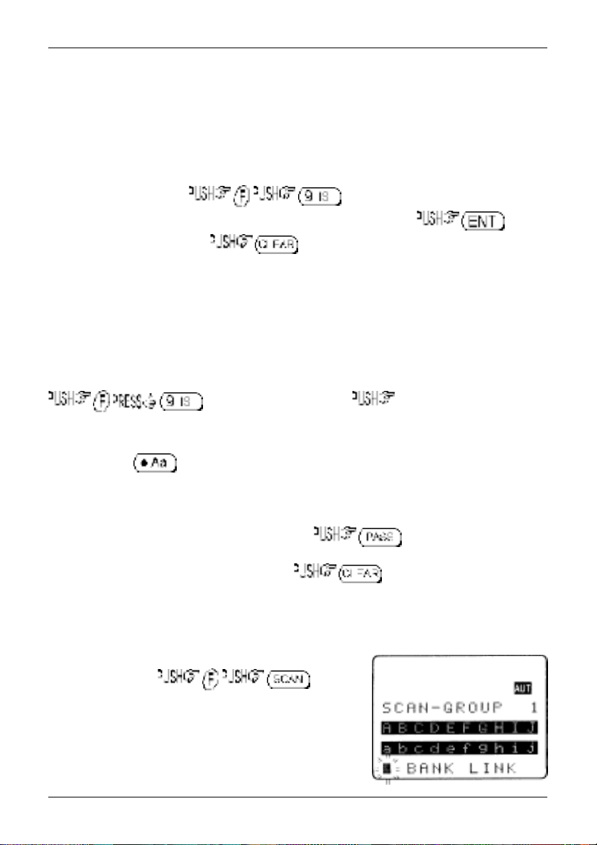
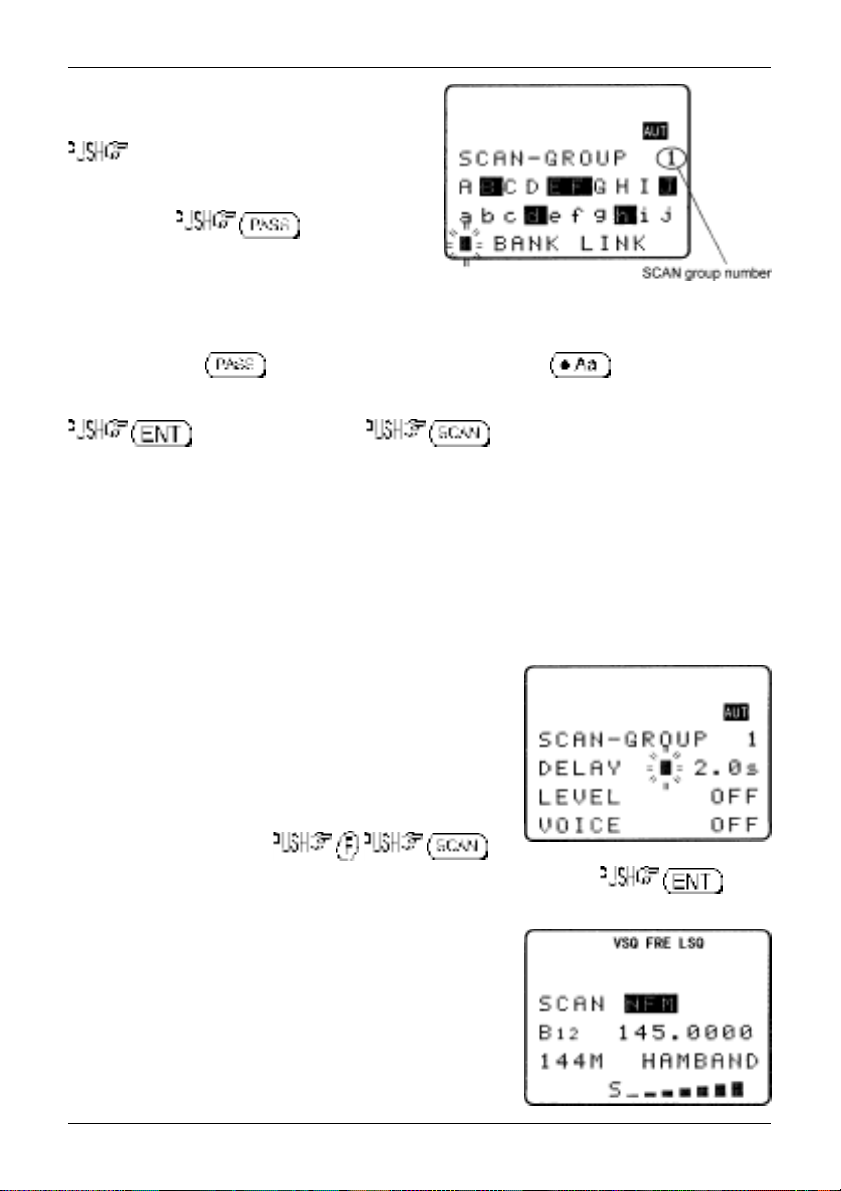
7-7 Scan bank link (scan group)
It is possible to custom define scan parameters for a single bank
or group of memory banks.
Use the key sequence to access
the “SCAN GROUP” menu. Bank “SCAN GROUP 0” contains a
default listing and cannot be overwritten (so displays “LINK OFF”
on the bottom line of the LCD), banks 1 to 9 are available for
custom programming.
Use the main dial or ï ð keys to select the SCAN GROUP
number, for SCAN-GROUP numbers 1 to 9 the legend
66
Section 7-7, 7-8
“BANK LINK” will be displayed on the bottom line of
the LCD indicating that programming is possible.
ò to move to the memory bank letters, then
reverse highlight the letters you wish to link together
as a group of memory channels to scan using the
ï ð ñ ò keys, to mark desired
memory banks, both upper and lower case letters may
be highlighted in the same group. The selected banks
(which will form a large scan group) will be displayed
in REVERSE contrast on the LCD.
It is also possible to use the keypad to quickly select the required banks for inclusion as a group, this
saves having to use to toggle selection, The CASE SHIFT key is used to toggle
between the upper and lower case memory bank listings.
to accept the data input. (one or twice) to start scanning if the
AR8200 is not already in scan mode. The memory banks grouped together in the SCAN GROUP will
form a large group during scan. The SCAN GROUP number (and associated data) will be used to define
current scan parameters.
For example:
these banks is scanned, all other banks in the group will be scanned in sequence over and over…
B > E > F > a > h > B > E > F > a > h etc (providing each of the banks contains stored memory
channels).
It is possible to scan ANY memory bank, even if it is not contained in the current SCAN GROUP list by
manually selecting the bank using the ï ð keys or keypad while in scan mode.
You can individually configure each of the nine SCAN GROUPS
1 to 9 with a different collection of banks. SCAN GROUP 0
cannot be changed as it contains the default of LINK OFF so
that you can quickly disable bank link when individual memory
scan is required. SCAN GROUP 0 also contains default
settings for DELAY, LEVEL, VOICE, FREE and MODE
parameters.
To change the active SCAN GROUP, access the SCAN GROUP
menu using the key sequence ,
select the desired SCAN GROUP (0 to 9) using the main dial or ï ð keys then to
accept the change and exit the menu.
If you group banks “B, E, F, a, h” as SCAN GROUP number “1”, then when any one of
7-8 Additional scan facilities
(Scan group environment - DELAY, LEVEL, VOICE, FREE, MODE)
It is possible to further customise the scan parameters for
each of the nine SCAN GROUPS (group 0 cannot be altered
as it contains the default information).
67
 Loading...