


Section 1, 1-1
(1) SDU5500 Index
1 |
Index ............................................................................................ |
1 |
1-1 |
Introduction .................................................................................. |
1 |
1-2 |
Taking care of the unit .................................................................. |
2 |
1-3 |
Power requirements ..................................................................... |
2 |
1-4 |
Operating anomalies .................................................................... |
2 |
1-5 |
Accessories supplied .................................................................... |
2 |
1-6 |
Technical high-lights ..................................................................... |
3 |
2 |
Controls and connections .......................................................... |
4 |
2-1 |
Front panel controls ...................................................................... |
4 |
2-2 |
Rear Panel ................................................................................... |
5 |
3 |
LCD, keys, legends & menus ..................................................... |
6 |
3-1 |
Description of LCD legends .......................................................... |
6 |
3-2 |
SDU5500 menu overview ............................................................. |
10 |
3-3 |
Important considerations .............................................................. |
14 |
3-3-1 |
LCD resolution ............................................................................. |
14 |
3-3-2 Significance of receive STEP size ................................................ |
14 |
|
3-3-3 Significance of RBW (Resolution Band Width) ............................. |
15 |
|
4 |
Making the SDU5500 ready for operation ................................. |
15 |
4-1 |
Configuration of the AR5000 companion radio ............................. |
15 |
4-2 |
Configuration of the AR3000A companion radio ........................... |
17 |
4-3 |
Configuration of an ICOM companion radio .................................. |
19 |
4-3-1 Example set-up for the ICOM IC-R7100 receiver ......................... |
20 |
|
4-3-2 Example set-up for the ICOM IC-R8500 receiver .......................... |
20 |
|
4-4 |
Operation with an “Other” companion receiver ............................. |
21 |
5 |
General operation of the SDU5500 ............................................ |
23 |
5-1 |
Using the SDU5500... sequence to use ........................................ |
23 |
5-2 |
Spectrum analyser mode .............................................................. |
28 |
5-3 |
Step resolution mode ................................................................... |
30 |
5-4 |
Channel scope mode ................................................................... |
33 |
5-5 |
Passive bandscope operation ...................................................... |
36 |
6 |
Special considerations .............................................................. |
37 |
7 |
Computer control information ................................................... |
38 |
8 |
Specification ............................................................................... |
42 |
1-1 Introduction
Thank you for purchasing the SDU5500 Spectrum Display Unit. For years AOR has been marketing the worlds’ first colour spectrum display unit SDU5000 for professionals and the top-end of hobbyist listeners. The SDU5500 is a worthy successor to the SDU5000, using a large high resolution LCD display (similar to high priced dedicated spectrum analysers) backed by the latest microprocessor technology to ensure high versatility and reliability. To get the best possible results, we recommended that you read this manual to fully familiarise yourself with the SDU5500.
Every effort has been made to make this manual correct and up to date. Due to continuous development of the product and by error or omission, anomalies may be found and this is acknowledged.
© This manual is protected by copyright AOR Ltd 1999. No information contained in this manual may be copied or transferred by any means without the prior written consent of AOR Ltd. AOR and the
AOR logo are trade marks of AOR Ltd. All other trade marks and names are acknowledged. E&OE
1

Section 1-2, 1-3, 1-4, 1-5
1-2 Taking care of the unit
There are no internal operator adjustments. In the unlikely event of servicing being required, please contact your dealer for technical assistance.
Do not use or leave the SDU5500 in direct sunlight (especially the LCD). It is best to avoid locations where excessive heat, humidity, dust and vibration are expected. Always keep the SDU5500 free from dust and moisture. LCD contrast & selection of negative / positive display may be adjusted via menus, adjust appropriately to your operating environment.
& Note: Never push or knock the LCD screen - which is very fragile and shock sensitive.
Daily care
Use a soft, dry cloth to gently wipe the SDU5500 clean, never use abrasive cleaners or organic solvents which may damage certain parts. Treat the unit with care, avoid spillage or leakage of liquids into the cabinet and power supply. Special care should be taken to avoid liquid entering around the keys, spin wheel dial or via the connection sockets.
1-3 Power requirements
Depending upon the world market area, the SDU5500 may be provided with either a suitable a.c./d.c. power unit or just the d.c. lead with correct d.c. plug type fitted. The SDU5500 is designed for operation from a nominal 12V d.c. regulated power supply (12 to 14V is acceptable), which should be capable of supplying a minimum of 1A continuous, ideally a 2A unit should be employed.
& Note: Never connect the SDU5500 directly to an a.c. supply.
The d.c. input socket uses a mini power connector subject to EIAJ RC-5320A and is wired centre positive (+), the cable is marked with a stripe identifying the positive connection, the chassis of the unit is at negative ground. To minimise the potential for power cable interference, it is suggested that a ferrite clamp be fitted to the connecting cable.
& SAFETY NOTICE - Always disconnect the power supply from the a.c. socket when not in use.
1-4 Operating anomalies
Should the SDU5500 appear to behave strangely, normal operation may easily be regained by resetting the microprocessor. Simply power down the SDU5500 and disconnect the power supply... leave for 30 seconds then re-connect and power-up again.
1-5 Accessories supplied
The following items are provided in the carton box:
1 x |
Control lead for the AR5000 (9-pin to 9-pin D-type male) |
|
|
1 x |
BNC patch lead for IF connection |
|
|
1 x |
Operating manual |
|
|
1 x |
a.c. power supply or d.c. cable |
|
(in this case the white stripe is positive) - depending upon world market area. |
|
|
& Note: If used with the AR3000A, a small modification is required to the receiver in order to provide the required 10.7 MHz IF output. If using the ICOM IC-R7100 or IC-R9000, the optional ICOM CT17 (RS232/CIV) interface is required.
2

Section 1-6
1-6 Technical high-lights
• Menu driven operation
All facilities are accessible via dedicated keys and on-screen menus.
• Full inter-connection with the AR5000
The AR5000 can be operated from the SDU5500 providing selection of centre frequency, receive mode, etc. Any frequency spotted and monitored by the SDU5500 may be received by the AR5000 straight away.
• Direct reading of receive frequency and input level
By placing the cursor on any spot frequency, you can read its frequency and input dBm level on-screen. When connected with the AR5000, the SDU5500 virtually works as a spectrum analyser over the frequency range of 10kHz to 2600MHz as the centre frequency is always the receive frequency in spectrum analyser mode.
• Wide spectrum coverage
The SDU5500 covers a maximum of 10 MHz (± 5MHz) spread against the input frequency.
• Dual frequency resolution
SDU input filters may be toggled between 5kHz or 30kHz resolution.
• Wide input range Input range
Of -10dBm to -90dBm by using 2 selectable gain settings.
•Highly accurate frequency management
Through the DDS controlled Local Oscillator circuit.
•Graphical display
Wide variety of graphical display and statistical analysis.
• Remote control via PC
All keyboard operations of the SDU5500 can be mimicked by PC via RS232. Also acquired data can be downloaded to PC.
• Compatibility with non-AOR receivers
Any companion radio receiver which is equipped with a 10.7MHz IF output may be used with the SDU5500. It is possible to use a companion receiver with an IF not of 10.7 MHz but within the range of 5.7 to 15.7 MHz by reprogramming the IF frequency employed by the SDU5500, however In order to provide a useful bandwidth of at least 1 MHz (+/- 500kHz), as a rule of thumb, the limits of IF should be considered as 6.7 to 14.7 MHz. Sweep direction is selectable depending on the heterodyne configuration of the radio, however the maximum sweep span may be narrower than 10 MHz due to the IF characteristics and IF frequency of the companion radio. If being used with and ICOM IC-R7100 or IC-R9000, the optional ICOM CT-17 (RS232/CIV) interface will be required.
3
Section 2, 2-1
(2) Controls and connections
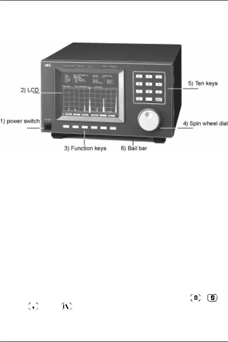
2-1 Front panel controls
The front panel of the SDU5500 is dominated by the large LCD. Controls are ‘grouped’ to assist efficient operation, there are a total of 18 keys in addition to the on/off switch and spin wheel dial.
1 Power switch
Press once to latch the switch in, switching on the SDU5500. To switch off the SDU5500, press the switch a second time, the switch latches outward.
2 Liquid Crystal Display
The large high resolution back-lit LCD defaults to white graphics & text on a blue background with the bottom-row functions in reverse contrast. The colours may be reversed (blue graphics & text on a white background) and the contrast may be adjusted.
3 Function keys
Six function keys are located under the LCD. There is no ‘printed legend’ accompanying the keys as their operations are defined by which menu is active on the LCD... there are a total of seven menus numbered from 1 to 7 inclusive (the menu number is ALWAYS displayed in the extreme lower-left corner of the LCD). This implementation is often referred to as “soft keys”.
4 Spin wheel dial
A rotary encoder is provided to simplify movement of the marker position on the LCD. This is very convenient and is the most natural method of marker frequency change. The marker is displayed as a thin vertical line with downward / upward triangles further easing visibility. The current marker numeric frequency reading is displayed directly above the graticule, along with signal level in dBm.
5 Numeric ‘ten keys’ |
|
|
|
|
|
|
|
|
|
|
|
|
|
|
|
|
||||||||
The entry of centre-frequency (receive frequency) is via the ten keys which are labelled |
|
|
|
|
|
|
to |
|||||||||||||||||
|
|
|
|
|
||||||||||||||||||||
plus decimal |
|
|
|
|
|
and enter |
|
|
|
|
|
|
|
|
|
|
. |
|
|
|
|
|
|
|
|
|
|
|
|
|
|
|
|
|
|
|
|
|
|
|
|
|
|
|
|
|
|||
|
|
|
|
|
|
|
|
|
|
|
|
|
|
|
|
|
|
|
|
|
|
|||
|
|
|
|
|
|
|
|
|
|
|
|
|
|
|
|
|
|
|
|
|
|
|
|
|
6 Bail bar
A tilt bail bar is provided under the front panel (on the bottom case half) so that the SDU5500 may be tilted upward at the front to improve visibility in certain installations.
4
Section 2-2
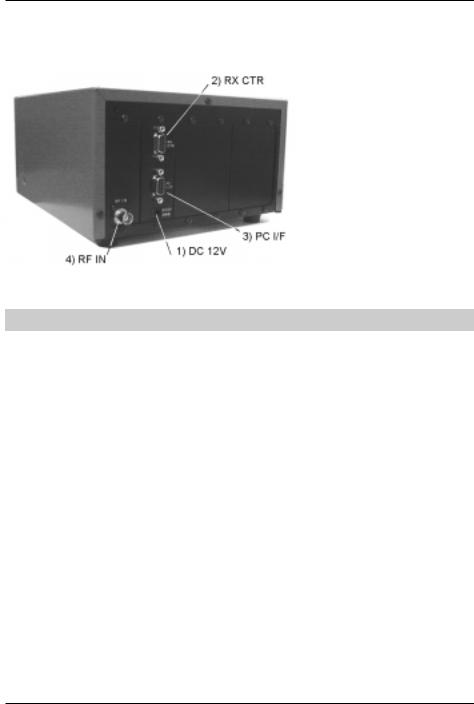
2-2 Rear Panel
The rear of the SDU5500 features two 9-pin D-type sockets for connection to the companion radio and PC, a BNC socket is provided for IF input and a d.c. input socket for power. Blanking plates cover the unused sections of the rear panel, these are for possible future expansion / options.
1 DC 12V (d.c. input power socket)
Connect a suitable regulated 12V d.c. power supply to this socket using the supplied connection lead, the power supply should have a minimum continuous capacity of 1A or greater, ideally a 2A supply should be employed.
The connector is subject to EIAJ RC-5320A and is wired centre positive (+), the cable is marked with a stripe identifying the positive connection.
To minimise the potential for power cable interference, it is suggested that a ferrite clamp be fitted to the connecting cable. (In some market areas a suitable power supply may be provided).
& Note: Never connect the SDU5500 directly to an a.c. supply.
2 RX CTR (receiver connection socket)
The supplied 9-way to 9-way ‘D-type’ male to male lead is used to connect the SDU5500 to the AR5000 receiver. If used with another receiver, a suitable serial-adapter or connecting cable will be required. Wiring should be as follows:
SDU5500 9-pin male |
9-pin male (AR5000) |
25-pin male (AR3000A) |
|
2 |
2 |
3 |
|
3 |
3 |
2 |
|
5 |
5 |
7 |
GND |
7 |
7 |
4 |
|
8 |
8 |
5 |
|
|
|
|
|
3 PC I/F PC (PC control socket)
A controlling computer may be connected to this 9-pin D-type female socket. As the socket is identical to that used for the companion radio connection, great care should be taken to avoid connection to the incorrect socket. Although it is very unlikely that incorrect connection may cause damage, it will cause unnecessary delay in placing the SDU5500 into useful operation.
5

Section 2-2, 3, 3-1
If connecting to a PC, observe the following connection requirements, use a straight RS232 lead (avoid null modem leads, these will not operate):
SDU5500 9-pin |
PC 9-pin |
PC 25-pin |
|
|
|
|
|
2 |
2 |
3 |
|
|
|
|
|
3 |
3 |
2 |
|
5 |
5 |
7 |
GND |
7 |
7 |
4 |
|
8 |
8 |
5 |
|
The SDU5500 is fully controllable by PC via the built-in RS232 interface, this includes all keyboard operations and down loading of the displayed data.
Communication parameter
Data length |
8 bit |
|
|
Parity bit |
None |
|
|
Stop bit |
2 bit |
Baud rate |
9600 |
Flow control |
X flow |
4 RF IN (Intermediate Frequency input socket)
The IF output (10.7 MHz) from a suitable receiver such as the AR5000 should be connected to this BNC input socket using a 50 OHM patch lead constructed of quality coaxial cable such as RG58/U, UR43, UR76 etc.
(3) LCD, keys, legends & menus
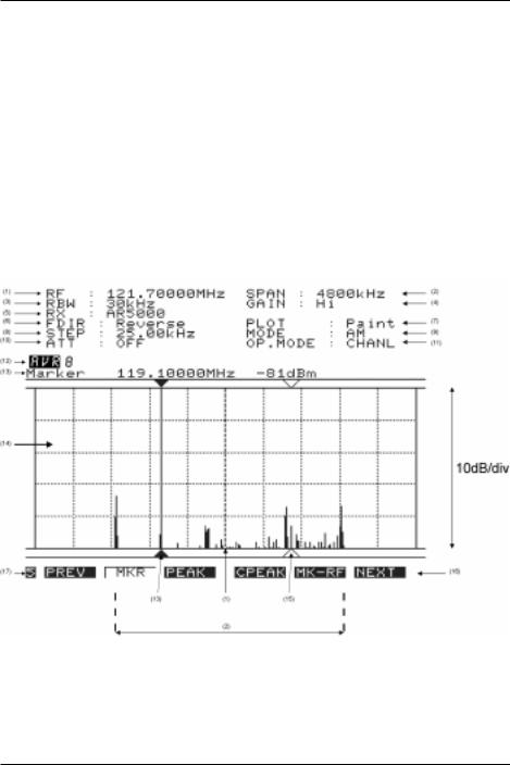
3-1 Description of LCD legends
The LCD is effectively split into three main sections, the top operating environment, the middle spectrum trace and the bottom menu selection. A total of 17 specific LCD areas are employed:
Top legends
The top of the LCD provides operational information, a summary is as follows:
CF |
Centre Frequency (frequency at the middle of the graticule) in MHz. |
RBW |
Resolution Band Width, sampling resolution 5kHz / 30kHz. |
RX |
Type of companion radio configured. |
|
|
FDIR |
Frequency sweep direction (ignore unless set to ‘Other’ companion radio type). |
STEP |
Receive tuning step in kHz. |
|
|
ATT |
Companion radio attenuator status On/Off (cannot accommodate 0/10/20dB selection). |
|
|
SPAN |
Total bandwidth of spectrum display in kHz. |
|
|
GAIN |
Toggles the SDU5500 internal amplifier between high and low gain. |
|
|
PLOT |
Type of trace, Outline or Paint. |
|
|
MODE |
Receive mode (NFM, AM, AUTO etc) |
|
|
OP.MODE |
Type of operation employed, SPECT (spectrum), STRES (step resolution), |
|
CHANL (channel scope). |
6
Section 3-1
Middle, graphical display
The middle section of the LCD is mapped into a graticule of ten boxes horizontally and five boxes high. The horizontal scale is determined by the SPAN (see later under LCD resolution). The vertical scale is calibrated in 10dBm increments ranging from:
•
•
Hi gain: Baseline is -90dBm with the top line representing -40dBm.
Low gain: Baseline is -60dBm with the top line representing -10dBm.
Directly above the graticule, the current “Marker” frequency is displayed in MHz with the signal level displayed in dBm to the right of the frequency. The marker position is controlled using the spin wheel dial.
Bottom menu soft keys
The bottom of the LCD is occupied by a number of soft keys arranged in seven menus. The mix of keys varies depending upon operational mode selected. Please refer to section 3-2 of this manual for a menu overview.
A summary of the 17 LCD areas is presented here:
(1) CF/RF Centre Frequency / Receive Frequency
A frequency at the centre of the screen is always indicated in MHz, the finest resolution is 10 Hz. In spectrum display and step resolution modes, the legend “CF” (Centre Frequency) is displayed to the left of the frequency. In channel scope mode the legend “RF” (Receive Frequency) is displayed to the left of the frequency.
7

Section 3-1
(2) SPAN Total displayed bandwidth
The centre frequency appears in the middle of the display with frequency extending to the left and right. The total frequency spread from the left through centre to the right is referred to as the total SPAN and is indicated in kHz. The maximum span is 10000 kHz (10 MHz) and minimum is 1 kHz.
(3) RBW Resolution Band Width
Two input filters may be toggled for sampling, 5 kHz and 30 kHz. Greater detail is obtained by 5 kHz, often with a lower baseline while 30 kHz provides faster refresh rates.
(4) GAIN SDU5500 input gain
The input stage of the SDU5500 has two gain settings Hi / Low, this is selectable from menu 2. Input gain is measured at the input of the SDU5500, not at the companion radio aerial socket. The difference between high and low gain setting is about 30dB.
(5) RX Companion radio type
The type of companion radio is displayed (selected from those available in RX configuration menu). When no specific companion radio is connected “Other” is automatically indicated.
(6) FDIR Frequency Direction
This function enables the SDU5500 to display the frequency in normal (left is lower frequency from the centre cursor) or reverse (left is higher frequency from the centre cursor). This is useful depending the type of superheterodyne receiver configured while in “Other” operation. The direction is automatically determined when using one of the supported radio receivers (so the menu item is not available, but selection is automatically displayed).
(7) PLOT Plot mode
Plot type can be PAINT or OUTLINE. Outline appears closer to the representation of a high priced dedicated spectrum analyser while paint is often easier to view.
(8) STEP Step frequency
Tuning step size of the companion radio is displayed in kHz format with a resolution of tens of Hz. (This is not the same as the LCD-step which is based upon the LCD resolution of 304 dots).
(9) MODE Receive mode
The companion radio receive mode is displayed. Not applicable when the radio type is set to “Other”.
(10) ATT Attenuator
Indicates whether the attenuator of the companion radio is ON or OFF. Not applicable when the radio type is set to “Other” nor with certain radio models.
(11) OP.MODE SDU5500 Operating mode
Three operating modes are provided and may be selected from menu 3:
•
•
•
SPECT: Spectrum analyser mode
STRES: Step resolution mode
CHANL: Channel scope mode
(12) AVR / MAX Averaging and maximum level
Averaging and Maximum level may be selected from menu 6. When “MAX” is selected, the traces on the LCD are frozen to indicate the strongest signals encountered (if you look very carefully, you will see that the trace is still updating). To cancel MAX press the [MAX] key a second time. When “AVR” is selected, the sampling rate is indicated and signals will be averaged over a number of sweeps.
8

Section 3-1
To cancel AVR, press [AVR] a second time.
(13) Marker Marker / Peak / CPeak
Selection of Marker / Peak / Continuous Peak is made via menu 5 and indicated on the LCD.
In normal spectrum mode, “Marker” is displayed and the spin wheel dial may be used to move the marker position indicated by a vertical bar with triangular symbols. The frequency and strength of traces may be read in this manner. The frequency and level can only be read within the confines of the graticule (out of range reading cannot be made).
“Peak” is displayed when peak hold is activated, the maximum strength of incoming signals will be frozen on the LCD until the peak facility is disengaged (finishing the current session) or SDU5500 switched off. The spin wheel dial may be used to hop between peaks in order of amplitude.
When “CPeak” is selected, the marker automatically hops to the largest new signal once a sweep has completed, the frequency of the transmission is displayed to the right of the “CPeak” legend. If you wish to monitor the automatically identified transmission, press [MK-CF] before a new sweep completes, this MOVES THE MARKER TO CENTRE FREQUENCY where it may be monitored through the companion radio.
(14) Signal display graticule
Received frequencies are plotted on the horizontal scale and signal strength on the vertical scale, showing the over-all effect of signal activity over the given frequency bandwidth (span).
The bottom horizontal line is the ‘baseline’. When signals are encountered, they produce vertical lines, the higher the line, the stronger the signal. A 50dB range is provided by the graticule which is divided into 10dB increments.
•
•
Hi gain: Baseline is -90dBm with the top line representing -40dBm.
Low gain: Baseline is -60dBm with the top line representing -10dBm.
By carefully selecting the gain, it is possible to obtain a total of 80dB between the two settings (from -90dBm to -10dBm).
(15) Receive Marker
A vertical dotted line with ‘outline triangle markers’ indicates the receive frequency when using channel scope mode. This is the frequency to which the companion radio is tuned and monitoring.
(16) Menu number
The current menu number (for each of the seven menus) is indicated in the lower left corner of the LCD. Use the PREV NEXT keys to move between menus or as a short cut, press the wanted menu number using the ten-key pad.
(17) Function keys
Six function keys are presented horizontally underneath the graticule, each being assigned with a specific task. The ‘soft key labels’ will be displayed above the function keys on the LCD page-by-page when the menu is scrolled.
9
Section 3-2
3-2 SDU5500 menu overview
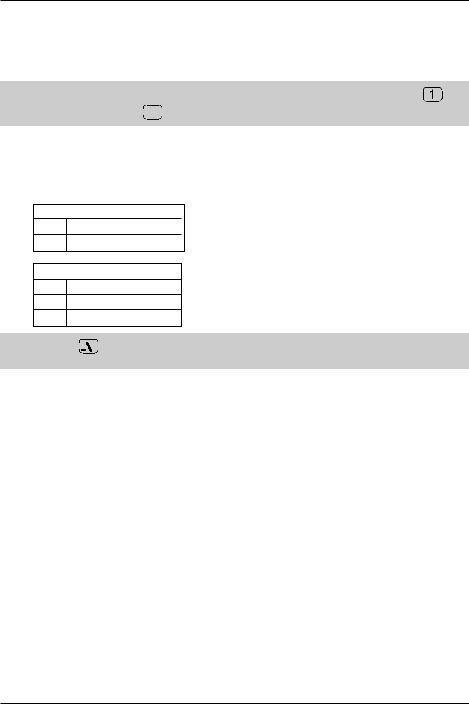
Operation of the SDU5500 is controlled by seven menus numbered 1 to 7. The menu number is always displayed in the bottom left of the LCD, even when information is being keyed. The radio type is defined in menu 1. Use the PREVIOUS MENU PREV and NEXT MENU NEXT keys to move between menus.
& Note: As a short-cut to menus, it is also possible to use the numeric ten-key pad... so that
immediately accesses menu 1, 

 accesses menu 5 etc.
Some omission and duplication appears in menus (such as STEP in some operating modes) as facilities change with operating condition.
While inputting numeric data or defining companion radio type, addition sub-menus are often displayed. The soft keys offer the following facilities:
ESC ENT
ESC: Exit / abort / terminate
ENT: Enter / accept data
ESC BS ENT
ESC: Exit / abort / terminate
BS: Back space
ENT: Enter / accept data
& Note: Either 


 key may be used to complete data entry, on the ten-keypad or soft menus when offered.
A quick menu guide is presented here:
Spectrum analyser mode (SPECT) |
|
|
|
|||
1 |
PREV |
RX |
PLOT |
CONT |
B/W |
NEXT |
2 |
PREV |
MODE |
STEP |
ATT |
GAIN |
NEXT |
3 |
PREV |
SPECT |
STRES |
CHANL |
- |
NEXT |
4 |
PREV |
CF |
SPAN |
RBW |
- |
NEXT |
5 |
PREV |
MKR |
PEAK |
CPEAK |
MK-CF |
NEXT |
6 |
PREV |
MAX |
AVR |
- |
- |
NEXT |
7 |
PREV |
<<- |
<- |
-> |
->> |
NEXT |
Step resolution mode (STRES) |
|
|
|
|||
1 |
PREV |
RX |
PLOT |
CONT |
B/W |
NEXT |
2 |
PREV |
MODE |
STEP |
ATT |
GAIN |
NEXT |
3 |
PREV |
SPECT |
STRES |
CHANL |
- |
NEXT |
4 |
PREV |
CF |
STEP |
RBW |
- |
NEXT |
5 |
PREV |
MKR |
PEAK |
CPEAK |
MK-CF |
NEXT |
6 |
PREV |
MAX |
AVR |
- |
- |
NEXT |
7 |
PREV |
<<- |
<- |
-> |
->> |
NEXT |
10
Section 3-2
Channel scope mode (CHANL) |
|
|
|
|||
1 |
PREV |
RX |
PLOT |
CONT |
B/W |
NEXT |
2 |
PREV |
MODE |
- |
ATT |
GAIN |
NEXT |
3 |
PREV |
SPECT |
STRES |
CHANL |
- |
NEXT |
4 |
PREV |
FREQ |
- |
RBW |
- |
NEXT |
5 |
PREV |
MKR |
PEAK |
CPEAK |
MK-CF |
NEXT |
6 |
PREV |
MAX |
AVR |
- |
- |
NEXT |
7 |
PREV |
- |
<- |
-> |
- |
NEXT |
‘Other’ companion radio |
|
|
|
|
||
1 |
PREV |
RX |
PLOT |
CONT |
B/W |
NEXT |
2 |
PREV |
- |
STEP |
- |
GAIN |
NEXT |
3 |
PREV |
SPECT |
STRES |
- |
- |
NEXT |
4 |
PREV |
CF |
SPAN |
RBW |
FDIR |
NEXT |
5 |
PRE |
MKR |
PEAK |
CPEAK |
MK-CF |
NEXT |
6 |
PREV |
MAX |
AVR |
- |
- |
NEXT |
7 |
PREV |
<<- |
<- |
-> |
->> |
NEXT |
1 |
Menu 1 |
PREV |
Move to previous menu |
RX |
Companion radio type |
PLOT |
Toggles between outline and paint |
CONT LCD contrast (0 to 160) around 50 is usually best
B/W Toggles between an Blue and White background
NEXT Move to next menu
2 |
Menu 2 |
PREV |
Move to previous menu |
MODE Companion radio receive mode |
|
|
(not available in ‘Other’ radio operation) |
STEP |
Companion radio tuning step size in kHz. |
|
(not available in channel scope mode) |
ATT |
Toggles the companion radio attenuator |
|
on/off (not available in ‘Other’ radio |
|
operation) |
GAIN |
Toggles the SDU5500 gain between |
|
Hi and Low |
NEXT |
Move to next menu |
11

Section 3-2
3 |
Menu 3 |
PREV |
Move to previous menu |
SPECT |
Places the SDU5500 into spectrum |
|
analyser mode (default) |
STRES |
Step resolution mode |
CHANL |
Channel scope mode (not available |
|
in ‘Other’ radio operation) |
NEXT |
Move to next menu |
4 |
Menu 4 |
||||||||||||||||||||||||||||||||||||||||||||||||||
PREV |
Move to previous menu |
||||||||||||||||||||||||||||||||||||||||||||||||||
CF |
Receive frequency, enter via the |
||||||||||||||||||||||||||||||||||||||||||||||||||
|
ten keys in MHz. |
||||||||||||||||||||||||||||||||||||||||||||||||||
FREQ |
In channel scope mode the legend |
||||||||||||||||||||||||||||||||||||||||||||||||||
|
“FREQ” is displayed. This is used to |
||||||||||||||||||||||||||||||||||||||||||||||||||
|
access the sub menu to define |
||||||||||||||||||||||||||||||||||||||||||||||||||
|
start / end / step setting. |
||||||||||||||||||||||||||||||||||||||||||||||||||
SPAN |
When using SPECTRUM DISPLAY |
||||||||||||||||||||||||||||||||||||||||||||||||||
|
MODE “SPECT”, the viewable |
||||||||||||||||||||||||||||||||||||||||||||||||||
|
bandwidth may be set. Input is via |
||||||||||||||||||||||||||||||||||||||||||||||||||
|
the ten keys using kHz format. |
||||||||||||||||||||||||||||||||||||||||||||||||||
|
i.e. for 10 MHz bandwidth (+/- 5MHz) |
||||||||||||||||||||||||||||||||||||||||||||||||||
|
enter |
|
|
|
|
|
|
|
|
|
|
|
|
|
|
|
|
|
|
|
|
|
|
|
|
|
|
|
|
|
|
|
|
|
|
|
|
|
|
|
|
|
|
|
|
|
|
|
|
||
|
|
|
|
|
|
|
|
|
|
|
|
|
|
|
|
|
|
|
|
|
|
|
|
|
|
|
|
|
|
|
|
|
|
|
|
|
|
|
|
|
|
|
|
|
|
|
|
|
|
|
|
|
|
|
|
|
|
|
|
|
|
|
|
|
|
|
|
|
|
|
|
|
|
|
|
|
|
|
|
|
|
|
|
|
|
|
|
|
|
|
|
|
|
|
|
|
|
|
|
|
|
|
|
|
SPAN is not available in channel scope |
||||||||||||||||||||||||||||||||||||||||||||||||||
|
mode. |
||||||||||||||||||||||||||||||||||||||||||||||||||
STEP |
When using step resolution mode, the |
||||||||||||||||||||||||||||||||||||||||||||||||||
|
legend “STEP” will be displayed, see |
||||||||||||||||||||||||||||||||||||||||||||||||||
|
the definition in menu 2. |
||||||||||||||||||||||||||||||||||||||||||||||||||
RBW |
Toggles the input filter Resolution |
||||||||||||||||||||||||||||||||||||||||||||||||||
|
Band Width between 30 kHz and 5 kHz. |
||||||||||||||||||||||||||||||||||||||||||||||||||
FDIR |
When using ‘Other’ companion radio, |
||||||||||||||||||||||||||||||||||||||||||||||||||
|
the sweep direction may be reversed, |
||||||||||||||||||||||||||||||||||||||||||||||||||
|
at other times the key legend will |
||||||||||||||||||||||||||||||||||||||||||||||||||
|
be BLANK. |
||||||||||||||||||||||||||||||||||||||||||||||||||
NEXT |
Move to next menu |
||||||||||||||||||||||||||||||||||||||||||||||||||
5 |
Menu 5 |
PREV |
Move to previous menu |
MKR |
Selected by default. Returns the |
|
SDU5500 to ‘marker’ mode. |
PEAK |
Freezes the current spectrum trace to |
|
show signal peaks. |
CPEAK |
Automatically forces the marker to |
|
move to the highest peak immediately |
|
following a completed spectrum trace, |
|
continuous peak. |
MK-CF |
Force ‘marker frequency’ to equal the |
|
‘centre frequency’ where the trace |
|
may be monitored on the companion |
|
radio. If step size has been selected |
|
appropriately, the exact frequency will |
|
be corrected to the nearest increment |
|
(most appropriate receive frequency) |
NEXT |
Move to next menu |
12
Section 3-2
6 |
Menu 6 |
PREV |
Move to previous menu |
MAX |
When “MAX” is selected, the maximum |
|
height of traces are frozen on the |
|
display. This will result in ‘peaks’ |
|
where transmissions have taken place, |
|
one side effect is that the baseline will |
|
tend to build-up a 5 to 10dB solid bar |
|
due to random background noise. |
|
This is a useful facility to ‘trap’ |
|
occasional transmissions over a long |
|
time-scale and to check on band |
|
allocation for transmission licence |
|
issuers. Press MAX a second time to |
|
restore a normal trace. A reverse |
|
contrast “MAX” legend confirms selection. |
AVR |
When “AVR” is selected, the average height of traces are calculated and displayed on the |
|
LCD. This causes the display to be a little sluggish at detecting transmissions when they |
|
first appear but permits them to remain visible for longer when the transmission stops. The |
|
effect is a ‘wave’ of activity, useful for assessing band activity in a relatively short period of |
|
time. Once activated, the buffer size must be allocated between 2 and 32 frames inclusive. |
|
A reverse legend “AVR” is displayed on the LCD to confirm operation. While the buffer is |
|
loading, the number of frames is indicated until the programmed number has been sampled, |
|
after this point the specified number of frames will be averaged on an on-going basis. Press |
|
AVR a second time to restore a normal trace. A reverse contrast “AVR” legend confirms |
|
selection. |
NEXT |
Move to next menu |
7 |
Menu 7 |
PREV |
Move to previous menu |
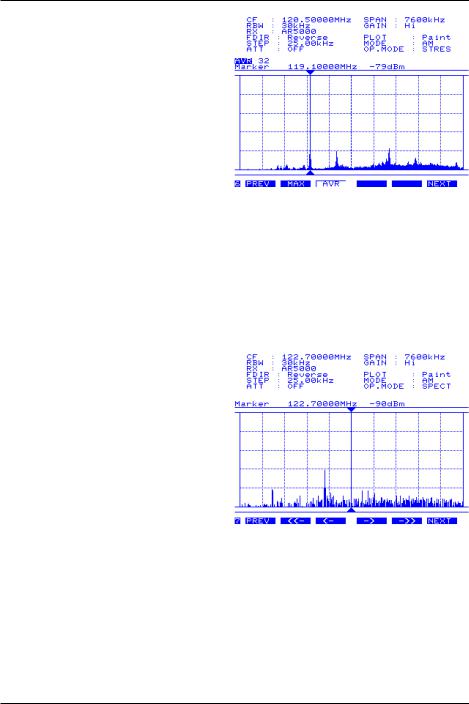
<<- |
Moves the centre frequency down by |
|
half the span. For example, if the span |
|
is set to 10000 kHz (10 MHz), the centre |
|
frequency will be lowered by 5000 kHz |
|
(5 MHz)... so that a centre frequency of |
|
123 MHz would become 118 MHz. |
|
Not available in channel scope mode. |
<- |
Moves the centre frequency down one |
|
channel step. i.e. if the receive |
|
frequency is 125 MHz and step is |
|
25 kHz, the centre frequency will move |
|
down by 25 kHz to 124.975 MHz. |
-> |
Moves the centre frequency up one |
|
channel step. i.e. if the receive |
|
frequency is 125.000 MHz and step is 25 kHz, the centre frequency will move up 25 kHz to |
|
125.025 MHz. |
->> |
Moves the centre frequency upward by half the span. For example, if the span is set to |
|
10000 kHz (10 MHz), the centre frequency will be increased by 5000 kHz (5 MHz)... |
|
so that a centre frequency of 123 MHz would become 128 MHz. Not available in channel |
|
scope mode. |
NEXT |
Move to next menu |
13
 Loading...