


®
FFT spectrum display unit
SDU5600
PROFESSIONAL SPECTRUM DISPLAY UNIT FOR USE WITH A COMPANION RADIO
OPERATING MANUAL
1
2

|
|
Index |
Index |
|
|
Safety notices ................................................................................................. |
5 |
|
SDU5600 brief circuit description .................................................................... |
6 |
|
LCD resolution ................................................................................................ |
6 |
|
Block diagram ................................................................................................. |
7 |
|
Introduction ..................................................................................................... |
8 |
|
1 Controls and Descriptions ......................................................................... |
9 |
|
1.1 |
Front panel ................................................................................................ |
9 |
1.2 |
Rear panel ................................................................................................ |
10 |
2 Connection ................................................................................................. |
11 |
|
2.1 |
Connection with the power supply ............................................................. |
11 |
2.2 |
Connection with the receiver ..................................................................... |
11 |
3 Preparations ............................................................................................... |
12 |
|
3.1 |
Configuration of the receiver ..................................................................... |
12 |
3.2 |
Start-up ..................................................................................................... |
12 |
4 Basics ......................................................................................................... |
13 |
|
4.1 |
Control ...................................................................................................... |
13 |
4.2 |
Display ...................................................................................................... |
14 |
4.3 |
Main key layout ......................................................................................... |
15 |
4.4 |
Clear (CLR) key ........................................................................................ |
16 |
4.5 |
Default mode and clear mode ................................................................... |
16 |
4.6 When the communication with the companion receiver has failed ............. |
16 |
|
5 Configuration of the SDU5600 ................................................................... |
17 |
|
5.1.1 Configuration (CONF) ............................................................................. |
17 |
|
5.1.2 Applicable receivers ............................................................................... |
18 |
|
5.2.1 Configuration of the receiver .................................................................. |
19 |
|
5.2.2 Selecting the receive frequency .............................................................. |
20 |
|
5.3 |
Setup of the monitoring mode ................................................................... |
22 |
5.4 |
Basic setup for each monitoring mode ...................................................... |
23 |
5.4.1 Spectrum analysers mode ...................................................................... |
23 |
|
5.4.2 Step resolution mode ............................................................................. |
24 |
|
5.4.3 Channel scope mode ............................................................................. |
25 |
|
5.4.4 Common features shared by different monitoring ................................... |
26 |
|
3

Index
5.5 |
Marker ...................................................................................................... |
28 |
5.6 |
Calculation facility ..................................................................................... |
30 |
5.7 |
Waterfall display facility ............................................................................. |
31 |
5.8 |
On/off of the display information ............................................................... |
32 |
5.9 |
Beep alert ................................................................................................. |
32 |
5.10 Factory default/reset ............................................................................... |
32 |
|
6 Operating the SDU5600 ............................................................................. |
33 |
|
6.1 Operate the SDU5600 with the AR5000A+3 .............................................. |
33 |
|
6.2 |
Monitor the VHF FM band in the spectrum analyser mode ........................ |
34 |
6.3 |
Monitor the FM broadcast band in the step resolution mode ..................... |
35 |
6.4 |
Monitor the VHF air band in the channel scope mode ............................... |
36 |
6.5 |
Suitable applications of each monitoring mode ......................................... |
37 |
7 Useful information ..................................................................................... |
38 |
|
8 SDU5600 Computer control ....................................................................... |
39 |
|
8.1 |
Communication parameters and connecting lead ...................................... |
39 |
8.2 |
Delimiter ................................................................................................... |
39 |
8.3 |
Basic format of the command ................................................................... |
40 |
8.4 |
RS232 command list ................................................................................ |
40 |
|
Spectrum analysis ............................................................................... |
41 |
|
Visual command .................................................................................. |
43 |
|
User interface ...................................................................................... |
44 |
|
General information ............................................................................. |
46 |
|
Notes for programmers ........................................................................ |
48 |
9 Specification .............................................................................................. |
49 |
|
4

Safety notices
Every effort has been made to make this manual correct and up to date. Due to continuous development of the product and by error or omission, anomalies may be found and this is acknowledged.
© This manual is protected by copyright AOR Ltd 2003. No information contained in this manual may be copied or transferred by any means without the prior written consent of AOR Ltd. AOR and the ‘AOR logo’ are trade marks of AOR Ltd. All other trade marks and names are acknowledged. E&OE
& Level of risk
As there SDU5600 is powered from 12V DC, there is little chance of serious injury as long as common sense is applied.
Observe the polarity of connections if the supplied AC power unit is not being used. DC input is a nominal 12V DC wired centre positive. Reverse polarity connection will damage the SDU5600 and potentially could lead to the risk of fire or explosion under severe circumstances.
Carefully handle the AC plug of the supplied AC power unit to prevent touching the terminals when inserting or removing from the AC socket. NEVER connect the SDU5600 directly to the AC supply.
SAFETY NOTICE - Always disconnect the power supply from the AC socket when not in use.
Explanation of risk warning mark
Whenever the book symbol & is used in this operating manual, an important point is being made which may relate to risk of personal injury or damage to the unit if ignored.
When the pointing finger  is used, the associated text provides useful operational information of special note (such as a tip). No risk or personal injury or damage is associated.
Handling the SDU5600
Use a soft, dry cloth to gently wipe the SDU5600 clean, never use abrasive cleaners or organic solvents which may damage certain parts. Treat the unit with care, avoid spillage or leakage of liquids into the cabinet and power supply. Special care should be taken to avoid liquid entering around the keys, main dial or via the connection sockets. Never push or knock the TFT LCD display screen which is very fragile and sensitive to shock.
Special remarks
Do not use or leave the SDU5600 in direct sunlight (especially the TFT display). It is best to avoid locations where excessive heat, humidity, dust and vibration are expected. Always keep the SDU5600 free from dust and moisture.
AC adaptor (power unit)
The SDU5600 may be provided with either a suitable AC / DC power unit. The SDU5600 is designed for operation from a nominal 12V DC regulated power supply (12 to 14V is acceptable), which should be capable of supplying a minimum of 1A continuous, ideally a 2A unit should be employed.
& Note: Never connect the SDU5600 directly to an AC supply.
The DC input socket uses a mini power connector (subject to EIAJ RC-5320A) and is wired centre positive (+), the chassis of the unit is at negative ground. To minimise the potential for power cable interference, it is suggested that a ferrite clamp be fitted to the connecting cable.
Other warnings
There are no internal operator adjustments. In the unlikely event of servicing being required, please contact your dealer for technical assistance.
Should the SDU5600 appear to behave strangely, normal operation may easily be regained by resetting the microprocessor. Simply power down the SDU5600 and disconnect the power supply... leave for 30 seconds then reconnect and power-up again.
It is possible to RESET the microprocessor, please refer to section 5-10, page 32 for further information.
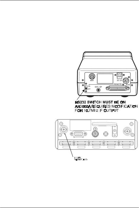
If used with the AR3000A, a small modification is required to the receiver in order to provide the required 10.7 MHz IF output. If using the ICOM IC-R7100, the optional ICOM CT17 (RS232/CIV) interface is required.
5

Circuit description
SDU5600 Brief circuit description
The RF signal is fed by BNC socket into the SDU at a selected frequency of either 10.7MHz or 45.05MHz depending on the radio IF frequency being used. This signal is split into two different signal paths depending upon which input frequency is selected. Both paths are buffered and have Band Pass Filters with a bandwidth of +/-5kHz to eliminate unwanted signals outside of this range.
After the BPF, both signal paths join and are amplified by a single LNA (Low Noise Amplifier). The output signal feeds a pair of Dual Balanced Mixers.
Here the input RF signal is mixed with two orthogonal sinusoidal signals produced by the DDS (Direct Digital Synthesis) section to give two resultant signals at audio frequencies (one used as real, one as imaginary). The gain of both signal paths is also controlled at this point.
The audio level signals are fed through 80kHz LPFs (Low Pass Filters) and finally converted from Analogue into Digital signals before being fed to the FPGA (Field Programmable Gate Array).
The digital signal is now processed by the DSP (Digital Signal Processor) to give an RGB Video output via the FPGA which drives a colour TFT LCD display.
The DSP is controlled by the main CPU and its EEPROM memory. The front panel keypad switches and rotary encoder are fed to the main CPU via a separate slave microprocessor on the front panel.
RS232 control and Receiver control ports connect (indirectly) to the main CPU.
A comprehensive power supply section has been used in the unit to give the required supply levels of 2.5v, 3.3v, 5v, 6v, 9.5v, 17v, -5v, -7v and -15v. The input is protected for reverse current & unwanted RF and is internally fused.
LCD resolution
The LCD provides high resolution of 320 horizontal dots from the left to right edges of screen. As a result, there are about 40 steps per graticule division with eight divisions making up the total width. The minimum displayed bandwidth is 160kHz and the maximum displayed width is 10000 kHz (10 MHz) representing ± 5 MHz.
To calculate the LCD-step, divide the SPAN bandwidth in kHz by 320. Examples are as follows:
10000 kHz (10 MHz) |
32.250 kHz |
|
|
|
|
5000 kHz (5 MHz) |
15.625 kHz |
|
|
|
|
2000 kHz (2 MHz) |
6.250 kHz |
|
|
|
|
1000 kHz (1 MHz) |
3.250 kHz |
|
|
|
|
160 kHz (0.16 MHz) |
0.500 kHz |
|
|
|
|
It is possible to force the LCD-step to equal the receive tuning step using a similar process. Multiply the receive tuning step size in kHz by 320 (dots) to obtain the required total span width in kHz.
For example, for a 5 kHz tuning and LCD step, 5 x 320 = 1600 kHz span
The following table presents commonly used step sizes:
0.5 kHz (minimum step size) |
160 kHz (0.160 MHz) |
|
|
5 kHz |
1600 kHz (1.600 MHz) |
|
|
6.25 kHz |
2000 kHz (2.00 MHz) |
|
|
9 kHz |
2880 kHz (2.880 MHz) |
|
|
10 kHz |
3200 kHz (3.200 MHz) |
|
|
12.5 kHz |
4000 kHz (4.000 MHz) |
|
|
20 kHz |
6400 kHz (6.400 MHz) |
|
|
25 kHz |
8000 kHz (8.000 MHz) |
|
|
31.25 kHz |
represents maximum span of 10000 kHz (10 MHz) |
|
|
6

Block diagram
7

Introduction & preparation
Introduction
Thank you for purchasing the SDU5600 FFT spectrum display unit. AOR was the first company in the world to market a colour spectrum display unit (SDU5000) for professionals and the top-end of hobbyist listeners. The SDU5500 followed adding sophistication and the SDU5600 is truly a successor incorporating a high resolution 5 inch (127mm) colour TFT display featuring FFT signal analysis and built-in waterfall display backed by the latest microprocessor technology to ensure high versatility and
reliability. To get the best possible results, we recommended that you read this manual to fully familiarise yourself with the SDU5600.
Major features
The SDU5600 has been designed to be a highly effective spectrum monitor unit which is capable of digitally processing the IF frequency taken from a communications receiver through the use of FFT for professional quality spectrum analysis. The 5 inch TFT colour LCD screen is used to achieve the finest possible resolution.
The SDU5600 has been primarily designed to complement to the AOR AR5000 series of receivers in terms of operational features and cosmetic design. Also other types of receiver such as the AOR AR-ONE, AR3000A and AR8600MK2 and ICOM ICR8500 + ICR7100 can be used (modification and additional hardware required).
A wide variety of monitoring modes are available with the convenience of operators in mind which include Step Resolution Mode for general monitoring or Channel Scope Mode for monitoring the channelised signals. It also incorporates a Waterfall facility (as commercial grade spectrum analysers do), to display the changing conditions of signal spectrum with varying colours in a form of waterfall.
Following the success of its predecessors, SDU5000 and SDU5500, the new SDU5600 provides the same AV, Peak Hold and Peak value readings which are downloadable to the PC via a communications port. The SDU5600 can be remote controlled through the use of the communications port to further expand the range of applications for spectrum monitoring.
Supplied accessories
1 x SDU5600 main unit
1 x BNC RF patch lead for IF connection
1 x DB9 patch lead for serial communications - male to male
1 x Handbook
1 x AC power supply
8
Section 1, 1-1
1 Controls and Descriptions
Control and display of the SDU5600 is via the front panel with the rear panel providing connections for the companion receiver, power and computer.
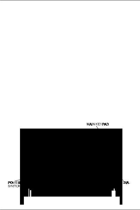
1-1 Front panel
LCD: The large high resolution 5 inch colour TFT display provides all operational information and spectrum display. The background is black with green graticule and white lettering for critical information. Menu items are varying shades of blue, the valid indicator is green with the function indicator in ‘reverse lettering’ yellow. The marker line is white and changes to purple when exactly positioned over a graticule line. The colours cannot be changed.
Power switch: Press once to latch the switch in, switching on the SDU5600. To switch off the
SDU5600, press the switch a second time, the switch latches outward. When switched on, the LCD briefly displays the model and firmware numbers.
Tilt bail bar: A tilt bail bar is provided under the front panel (on the bottom case half) so that the
SDU5600 may be tilted upward at the front to improve visibility in certain installations.
Soft function keys: Each one of these three ‘soft keys’ has multiple roles as indicated on the LCD screen depending on the circumstances in operation.
Special function keys: These three keys positioned to the left of the DIAL are to be used solely for specific purposes such as to enter a centre frequency, frequency span, display increment and input sensitivity.
Dial: The DIAL is a rotary control and is used to move the cursor, to make a selection or to move the marker/centre frequency.
Main keypad: Used to enter numeric information, to control the companion receiver, etc. When a valid key press is sounded, the SDU5600 will provide a high pitch ‘beep’ (happy), if an invalid key press is made, a low pitched ‘beep’ (sad) is sounded. The beep can be toggled on/off using the key sequence FUNC + 6 (BEEP), the default is on.
9
Section 1-2
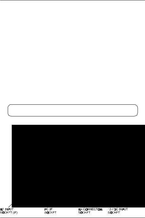
1-2 Rear panel
RF Input socket: The IF output (10.7 MHz / 45.05 MHz) from a suitable receiver such as the AR5000A should be connected to this BNC input socket using a 50 OHM patch lead constructed of quality coaxial cable such as RG58/U, UR43, UR76 etc. A suitable BNC-BNC lead is supplied.
PC I/F socket (male): A controlling computer may be connected to this 9-pin D-type male socket. Ensure this socket is only commented to a computer for hands-off operation, although it is very unlikely that incorrect connection to a computer or similar device would cause damage.
RX connection socket (female): The supplied 9-way to 9-way ‘D-type’ male to male lead is used to connect the SDU5600 to the AR5000A receiver. If used with another receiver, a suitable serialadapter or connecting cable will be required. Wiring should be as follows:
SDU5600 9-pin male |
9-pin male (AR5000A) |
25-pin male (AR3000A) |
|
|
|
|
|
2 |
2 |
3 |
|
3 |
3 |
2 |
|
5 |
5 |
7 |
GND |
7 |
7 |
4 |
|
8 |
8 |
5 |
|
|
|
|
|
12V DC input socket: The supplied power unit is terminated with a centre positive (+) polarity.
The plug specification follows EIAJ RC-5320A (Class-4).
There are four screw holes (unused), two on each side of the cabinet. They are a provision for rack mount application. Size of the screw is M4x8.
10
Section 2, 2-1, 2-2
2 Connection
2-1 Connection with the power supply
Where possible, use the supplied AC/DC power unit. Make sure the main switch of the SDU5600 is in the OFF position before connecting the power supply.
2-2 Connection with the receiver
This hand book is compiled mainly referring to the AR5000A series receiver as the principal companion receiver. Any reference to other types of receiver will be made separately when and where necessary.
Make sure that both the SDU5600 and AR5000A are switched off. Perform the connection of the both units referring to the photo shown here, using the IF signal connection patch lead and RX serial connection lead. The following table shows the correct connection of each plug & socket.
|
AR5000A |
SDU5600 |
IF signal patch lead |
IF OUT |
RF IN |
|
|
|
RX serial lead |
REMOTE |
RX CTR |
|
|
|
If you wish to use a receiver other than the AR5000A proceed to connect the 10.7MHz IF output from the receiver to the RF IN BNC socket on the rear of the
SDU5600... the AR3000A will require a modification in order to provide a suitable signal. Connect the RS232 data lead from the receiver to the RX CTR socket of the SDU5600, the companion receiver ‘thinks’ it is communicating with a computer, but is actually communicating
with the SDU5600 (the ICOM ICR7100 requires the optional ICOM CT17
CIV/RS232 interface).
RX Menu |
Applicable receiver |
Requirements |
|
|
|
|
menuselectionRXaoffersSDU5600The whichreceiversotherselectcanyouwhereby SDU5600.thewithoperatetowishyou receiveroftypetheindicatesheretableThein receiversapplicablemenu,selectionRXthe requirements.otherand |
AR5000 |
AR5000A+3 |
Configure the IF output |
|
|
AR5000A |
|
|
|
|
|
|
|
AR5000+3 |
|
|
|
AR5000 |
|
|
AR3000A |
AR3000A |
Modifications to the IF output circuit |
|
|
(AR3000 not applicable) |
|
|
|
|
|
|
AR8600 (10M) |
AR8600MK2 |
Modifications to the output circuits |
|
|
|
on all modes other than WFM |
|
|
|
|
|
AR8600 (45M) |
AR8600MK2 |
Modification of TV converter |
|
|
|
|
|
AR8200 |
AR8200MK2 |
Modification of TV converter and |
|
|
AR8200MK3 |
use of 8200PC interface |
|
|
|
|
|
AR-ONE |
AR-ONE |
Configure the IF output |
|
|
|
|
|
RFU5600 |
RFU5600 |
|
|
|
|
|
|
IC-R8500 |
IC-R8500 |
Use of batch lead with RCA/PHONO plug |
|
|
|
Configure the IF output |
|
|
|
|
|
IC-R7100 |
IC-R7100 |
Use of batch lead with RCA/PHONO plug |
|
|
|
Use of CT-17 interface |
|
|
|
|
|
11
Section 3, 3-1, 3-2
3 Preparations
3-1 Configuration of the receiver
The SDU5600 is primarily designed to operate with the receiver at 9600bps. The companion receiver’s baud rate has to be configured to the same rate. Some type of receivers may require additional modifications or interface, etc, which are explained as follows:-
AR5000 series: Configure the selection of external IF output and baud rate as per the following table (refer to pages 29 & 30 sections 6-18 & 6-19 of AR5000 English language operating manual):
External IF output |
Select [EXT-IF 1] |
|
|
RS232C |
Select 9600bps |
|
|
After the configurations have been completed place the receiver in VFO mode.
AR3000A: The AR3000A has to be modified by AOR in order to produce a 10.7MHz IF output for use with the SDU5600. The remote switch on the rear panel has to be set to ON position, and baud rate needs to be 4800bps (receiver’s default).
A screened RS232 connecting lead configured for 9-25 pin with male-pins at both ends must be used.
AR8200MK3: Configure the baud rate to 9600bps by referring to pages 109 & 110 section 14-6 of the AR8200 English language operating manual. Place the receiver in VFO mode. For connection to the
SDU5600 the 8200PC interface lead is required along with a gender changer. The AR8200MK3 has to be modified by AOR to produce a 10.7MHz IF output.
AR8600MK2: Configure the baud rate to 9600bps by referring to page 108 section 14-5 of AR8600 English language operating manual. Place the receiver in VFO mode. For connection to the SDU5600 the supplied connecting leads have to be used. To enable IF output in ALL
MODES (rather than just WFM), refer to page 18 for further information on the modifications required.
3-2 Start-up
ALWAYS switch the receiver on before the SDU5600 and make any necessary adjustment of communication speed and IF output (assuming the relevant modifications have been carried out and connecting leads are in place as appropriate). Then switch on the SDU5600 by depressing the
POWER switch on the lower left of the front panel. The SDU5600 will power up, while the operating system powers up you may notice horizontal lines on the LCD, this is normal. The SDU5600 will briefly display the model number and firmware version called the ‘opening message’ before the standard display. The SDU5600 is ready for operation.
12
Section 4, 4-1
4 Basics
This section describes the front panel controls, detail of LCD display and introduces the method of operation employed by the SDU5600 prior to further configurations and monitoring operations. It is advisable that you read this section carefully before proceeding to explore the full capability of the
SDU5600.
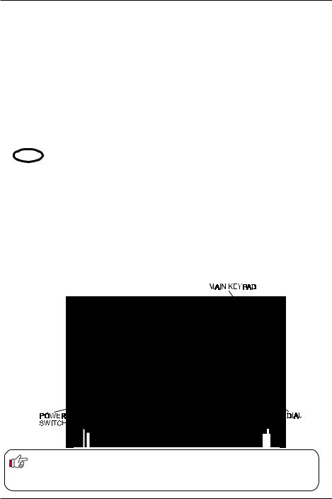
4-1 Control
Power switch: Press once to latch the switch in, switching on the SDU5600. To switch off the SDU5600, press the switch a second time, the switch latches outward. When switched on, the LCD briefly displays the model and firmware numbers.
Soft function keys: Each one of these three ‘soft keys’ has multiple roles as indicated on the LCD screen depending on the circumstances in operation. Throughout this manual, physical keys and ‘soft keys’ are not differentiated when describing key sequences.
Special function keys: These three keys positioned to the left of the DIAL are to be used solely for specific purposes such as to enter a centre frequency, frequency span, display increment and input sensitivity.
Dial: The DIAL is a rotary control and is used to move the cursor, to make a selection or to move the marker/centre frequency.
Main keypad: Used to enter numeric information, to control the companion receiver, etc.
BACKUP
The SDU5600 is configurable in various ways to the requirements of the operator. All configuration data is stored into FLASH ROM when the SDU5600 is switch off. However, in the event of failed connection / communications with the companion receiver, a beep will be sounded and the SDU5600 will revert to the factory default parameters.
13
Section 4-2
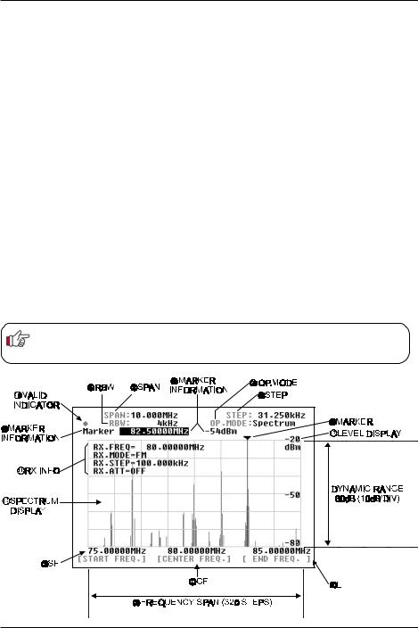
4-2 Display
This section explains what you can expect to see on the SDU5600’s monitor screen using Spectrum Mode as a typical example. The screen will appear differently when switched to other operating modes.
(1)Centre frequency - CF: The centre frequency reading is shown in MHz, providing a minimum resolution of up to 10Hz.
(2)Frequency span - SPAN: The centre frequency appears in the middle of the display with frequency extending to the left and right. The total frequency spread from the left through centre to the right is referred to as the total SPAN and is indicated in MHz.
The maximum span is 10MHz and minimum is 0.160MHz (160kHz). The horizontal scale is divided into 320 increments.
(3)Start frequency - SF: Displays the start frequency on the left of the graticule for calibration purposes. Usually the start frequency is calculated based on the centre frequency and bandwidth selected, but in certain menus can be directly programmed.
(4)End frequency - EF: Displays the end frequency on the right of the graticule for calibration purposes. Usually the end frequency is calculated based on the centre frequency and bandwidth selected, but in certain menus can be directly programmed.
(5)Resolution band width - RBW: The sampling filters may be selected from four bandwidths of 4kHz, 32kHz, 64kHz and 128kHz. The smaller bandwidths will provide greater detail of individual signals but wanted transmissions are easier to initially identify using a wider filter.
Relationship between Frequency span and Frequency step
The LCD provides high resolution of 320 steps from the left to right edges of the screen (x-axis). A frequency bandwidth represented by one step is calculated as STEP EQUALS SPAN DIVIDED BY 320, this being automatically done by the SDU5600 in the Spectrum Mode. Refer to item (6) ‘Frequency step’ on page 15.
14
Section 4-2, 4-3
(6)Step frequency - STEP: This value is displayed in kHz and indicates how wide one step represents out of the 320 steps across the X-axis. The example of page 14 shows 31.250kHz as one step which is obtained by taking the SPAN of 10MHz and dividing it by 320, the result is 31.250kHz - since the X-axis is 10MHz wide in this example. In the Step resolution mode, it is possible to specify the frequency bandwidth to be ‘one step’ rather than an often seemingly arbitrary value.
(7)Operation mode - OP.MODE: This legend indicates which one of three operating modes is selected, there are three possibilities:
Spectrum |
Spectrum analyser mode |
StepReso |
Step resolution mode |
Channel |
Channel scope mode |
(8) Marker + (9) Marker information: The marker (8) is a vertical line drawn on the LCD which can be moved across the horizontal axis. The marker is capable of providing the instantaneous reading of information where the marker is placed such as (9) frequency or signal strength of marker location.
In the marker menu, in addition to the instantaneous reading of marker information, the peak search facility is provided. Any signals which are out of scale cannot be read. It is necessary to adjust the gain for input signal level, the displayed signal appears vertically while the calibration lines of the graticule are represented horizontally.
(10)Valid indicator: This indicates which method of data input is valid. When a DOT ˜ is shown, the main dial is operational whereas when SQUARE ¢ is displayed, entry through the keypad is operational.
(11)Receiver information: This section of the LCD provides various operating conditions of the companion receiver such as receiving frequency, modulation mode, tuning step and ATT on/off.
The information can be toggle on and off via the key sequence FUNC 5 (DISP)
(12)Signal indicator + (13) Level indicator: The X-axis (horizontal line) indicates frequency, and
Y-axis (vertical line) indicates signal strength, so the frequency spectrum of the received signal is indicated on the screen.
The Y-axis (vertical line) is split into six segments with each segment representing a 10dB. The level indicator reads the input sensitivity which is shown along the Y-axis and the level is adjustable in four levels by altering the built-in amplifier (AMPLITUDE). The X-axis is split into eight segments indicating the frequency span (bandwidth) in use. The marker is designed to move across the one segment by ONE full rotation of the main dial. To move the marker from one edge to another requires
EIGHT rotations of the main dial.
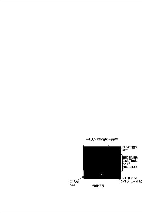
4-3 Main key layout
The main key pad consists of 20 individual keys, each conveniently located for ease of operation:
ê Function key (FUNC) on the top right
ê Receiver control keys (RX CTRL) on the right
ê Enter key (ENT) on lower right
ê Clear key (CLR) on bottom left
The FUNC key enables activation of the second function keys. When pressed the ‘FUNC’ legend appears in the top left corner of the LCD in reverse contrast YELLOW text.
15

Section 4-4, 4-5, 4-6
4-4 Clear (CLR) key
The clear key (CLR) acts as back-space key to cancel each proceeding key entry of numeric information (1 to 0, decimal-point) during entry of the start /end frequency, entry of input sensitivity / trigger level or the marker and numeration in the calculation mode. Pressing the clear key with no proceeding key entry will abort the sequence. Pressing A.CLR (FUNC + CLR) will clear all proceeding numeric entries and end the sequence.
Pressing the clear key (CLR) repeatedly in the calculation mode, marker mode (except the instantaneous reading) and waterfall display mode will eventually return operation to the default mode, see below.
4-5 Default mode and clear mode
The SDU5600 is configurable with a wide range of parameters. It is possible to bring the SDU5600 to the default mode as described in the table by repeatedly pressing the clear key.
Definition of the default mode
Marker mode |
Instantaneous reading |
|
|
Calculation mode |
None |
|
|
Waterfall mode |
No display |
|
|
Pressing the clear key (CLR) will not affect the proceeding key entry in the monitoring mode (spectrum analyser mode, step resolution mode, channel scope mode), frequency span / frequency step, marker frequency and demodulation mode.
4-6 When the communication with the companion receiver has failed
The SDU5600 will try to re-establish the communication with the receiver for a couple of seconds. If unsuccessful the SDU5600 will revert itself to the default mode as 4-5.
Default mode in the monitoring mode
When the communication between the SDU5600 and the companion receiver has been disrupted while operating in the channel scope mode the SDU5600 will automatically switch itself from the channel scope mode to spectrum analyser mode, ending up in the default mode.
16
 Loading...