


1 |
Contents |
|
|
|
|
|
|
2 |
Introduction, overview & quick reference .... |
2 |
6 |
Receiver operation - Main functions ............ |
14 |
||
2-1 Accessories supplied |
|
6-1 |
First switch-on |
|
|||
2-2 Overview - Read this if nothing else |
|
6-2 |
Filter calibration |
|
|||
2-3 Quick reference |
|
6-3 |
Memory restoration |
|
|||
2-4 Menu tree |
|
6-4 |
Changing receive frequency |
|
|||
2-5 Remote controller quick reference |
|
6-5 Changing reception mode |
|
||||
|
|
|
|
6-6 IF filter bandwidth selection |
|
||
3 |
Major Features ............................................... |
7 |
6-7 Passband Shift (PBS) |
|
|||
|
|
|
|
6-8 Audio tone controls |
|
||
4 |
Precautions .................................................... |
8 |
6-9 RF Gain (Attenuator and Preamp) |
|
|||
4-1 Location |
|
6-10 Automatic Gain Control (AGC) |
|
||||
4-2 Looking after your receiver |
|
6-11 |
IF Gain control |
|
|||
4-3 Power requirements |
|
6-12 |
Squelch control |
|
|||
4-4 Aerial (antenna) connection |
|
6-13 Beat Frequency Oscillator (BFO) |
|
||||
5 |
Controls and functions .................................. |
9 |
7 |
VFO functions ................................................ |
22 |
||
|
Front panel:- ................................................... |
9 |
7-1 Tuning control LOCK |
|
|||
5-1 On/Off power switch |
|
7-2 Selecting VFO-A and VFO-B |
|
||||
5-2 Liquid Crystal Display (LCD) |
|
7-3 Dual VFO operation |
|
||||
5-3 Main rotary tuning control - MAIN DIAL |
|
8 |
Memory facilities |
24 |
|||
5-4 Fast tuning button |
|
||||||
5-5 Mode selection buttons |
|
8-1 Preview memory contents |
|
||||
5-6 Volume control |
|
8-2 Store into memory |
|
||||
5-7 Spin-wheel |
|
8-3 Recall from memory |
|
||||
5-8 General button |
|
8-4 Memory scanning |
|
||||
5-9 Memory menu button |
|
8-5 Memory technical details |
|
||||
5-10 |
RF and IF settings button |
|
9 |
Setup, Timer and Config menu options |
28 |
||
5-11 |
Filter menu button |
|
|||||
5-12 |
Headphone socket |
|
9-1 Setup menu options |
|
|||
5-13 |
Bail bar |
|
9-2 Timer settings |
|
|||
5-14 |
Internal speaker |
|
9-3 Setting the clock |
|
|||
|
Rear panel:- ................................................... |
10 |
9-4 Config menu options |
|
|||
5-15 |
Computer control socket |
|
10 |
Optional accessories |
30 |
||
5-16 |
Auxiliary equipment socket |
|
|||||
5-17 |
DC power input |
|
11 |
Aerials (Antennas) and earth systems |
31 |
||
5-18 |
External speaker output socket |
|
|||||
5-19 |
Display contrast adjustment |
|
12 |
Propagation - short wave bands |
32 |
||
5-20 Ground (chassis) connection |
|
||||||
5-21 |
Wire aerial connection |
|
13 |
Technical specification |
33 |
||
5-22 |
Antenna selection switch |
|
|||||
5-23 |
50 OHM aerial socket |
|
13-1 |
Block diagram .............................................. |
IBC |
||
|
Infrared controller:- ....................................... |
12 |
|
|
|
|
|
5-24 |
Filter change key |
|
|
|
|
|
|
5-25 |
PBS change key |
|
|
|
|
|
|
5-26 |
Treble change key |
|
|
|
|
|
|
5-27 |
Bass change key |
|
|
|
|
|
|
5-28 |
Increase and decrease keys |
|
|
|
|
|
|
5-29 |
Tune-up and Tune-down keys |
|
|
|
|
|
|
5-30 |
Volume increase and decrease keys |
|
|
|
|
|
|
5-31 |
Store into memory key |
|
|
|
|
|
|
5-32 |
Memory preview key |
|
|
|
|
|
|
5-33 |
Change VFO key |
|
|
|
|
|
|
5-34 |
Mode select keys |
|
|
|
|
|
|
5-35 |
Number keys |
|
|
|
|
|
|
5-36 |
Backspace key |
|
|
|
|
|
|
5-37 |
Clear key |
|
|
|
|
|
|
5-38 |
Memory recall key |
|
|
|
|
|
|
5-39 |
Frequency entry keys |
|
|
|
|
|
|
AR7030 OPERATING MANUAL |
PAGE 1 |
2 Introduction
Thank you for purchasing the AOR AR7030 high dynamic range, short wave, all mode receiver. The AR7030 is designed using the very latest DDS (Direct Digital Synthesis) technology to ensure the highest levels of performance and reliability. A TCXO (Temperature Compensated Crystal Oscillator) is provided for high stability.
To get the best possible results from your AR7030 we recommended that you carefully read this manual and familiarise yourself with the receiver. Many apparent faults are often due to accidental mis-operation of the receiver so, if you think there is a problem, carefully read all of the manual before deciding to return the receiver for repair.
Every effort has been made to make this manual correct and up to date. Due to continuous development of the receiver and by error or omission anomalies may be found and this is acknowledged.
© This manual is protected by copyright AOR Manufacturing Ltd 1995, 1996. No information contained in this manual may be copied or transferred by any means without the prior written consent of AOR Ltd. AOR and the 


 logo are trade marks of AOR Ltd. All other trade marks and names acknowledged. E&OE
2-1 Accessories supplied
Mains power supply
Infrared remote controller and batteries
Operating manual
2-2 Overview - read THIS if nothing else
The AR7030 receiver pushes forward the frontiers of performance and microprocessor operation. In order to get the very best out of the receiver you will need to carefully read through all the sections of this handbook, however there are a few points worth noting first:-
a. The receiver has been designed to be compact and robust enough for transportable operation, and as such there are relatively few front panel controls. The infrared remote controller should be considered as an extension of the front panel, offering single button access to many primary functions. The receiver can be operated without the infrared controller but more button presses may be required to perform the same operation.
The infrared control input is accepted by sensors on both the front and rear panels of the receiver. If you cannot reliably enter commands with the controller in close proximity to the front panel, move it to one side of the receiver and make sure that an object behind the receiver will provide a reflection into the rear sensor. The infrared controller is powered by two AAA size 1.5V batteries (supplied) which have to be fitted before it can be used...
observe the polarity carefully.
You cannot harm the receiver by pressing buttons, turning knobs or exploring the menu options - experiment without worry. Only by using the receiver will you become fully conversant with its operation.
If you really mess up the settings, a LOAD DEFAULT facility has been included so that you can return the set to its out-of-box condition (except for frequency memory contents). Loading the defaults will ensure:- sensible filters are selected for each mode of reception, no PBS offset, no BFO offset for CW and DATA modes, maximum IF gain with AGC on, auto synchronous AM, auto RF attenuation, flat tone control settings, standard line output levels etc.
To load the default settings, press (to return to the SETUP menu), rotate the spin-wheel
 one click anticlockwise so that the legend Deflt Set is displayed, and then press the
  button. Loaded .. is briefly displayed in place of the clock to confirm selection.
Should the filters appear incorrectly aligned or nonsymmetrical, please refer to FILTER CALIBRATION in section 6-2 and look through section 6-1.
b. The receiver does not have a standard format of display readout - it can be configured to display time or pass band shift or filter selection or treble / bass tone selection or VFO selection or AGC or memory configuration... whatever YOU choose. The spin-wheel  and the
  button will retain their last assigned functions when the
  button is pressed allowing a selected function to be changed whilst the S-meter is displayed.
To return to the SETUP menu and CLOCK display, press  . To display the S-meter and return to the root level of the menu system, press
  .
.
You may tune the receiver, change the volume and reception mode or select fast tune whilst any menu is shown on the display because these front panel controls have only one dedicated function. These are fixed controls, and are indicated in this manual with white lettering on a black background, similar to the lettering on the front panel. Similarly the  and
and  buttons always have a defined function. The other receiver controls, arranged beneath the display, are referred to as SOFT-KEYS, because their function varies according to the context of the selected menus. In these cases the control description is displayed on the receiver’s LCD and in this manual with black lettering on a grey background. When no menu is displayed on the LCD - when the S-meter is shown - then the underlying buttons select the menu indicated on the panel:- MEMORY, RF / IF or FILTER.
c. Each mode can have, and will retain, a different filter bandwidth (chosen from those available), pass band shift (PBS) setting, BFO setting and AGC speed. When adjusting any of these settings the values are changed only for the current mode selected. Squelch value for NFM mode is held separately from the value for all other modes.
PAGE 2 AR7030 OPERATING MANUAL
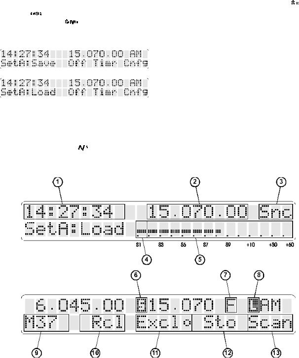
d. It is possible to save and load up to three of your favourite receiver set-ups, one for casual listening, one for serious DXing, one for data communication or whatever you choose. Each mode can have your own choice of filter bandwidth, pass band offset, BFO setting and AGC speed, along with global settings of the tone controls, auto / manual synchronous AM, auto / manual RF attenuator and line output levels. All these settings can be held in one of the SETUP MEMORIES, A, B or C. Using the setups can avoid having to recall many different menus, and provides a useful short cut to changing listening modes.
The setup memories are accessed through the SETUP menu by turning the spin-wheel  until the required memory (A, B or C) is selected along with the required function:-
  to setup the receiver with the settings held in the memory or
  to transfer the receiver’s settings into the memory. Press the
 button to actually load or save the setup.
e. The AR7030 has two VFOs, A and B - (Active and Background). Each VFO holds settings of volume, tone, receive frequency, reception mode, filter bandwidth, PBS, BFO, RF attenuator, IF gain, AGC speed, squelch, scan delay time and scan mode. The contents of the VFOs can be exchanged using the button, only the active VFO can be tuned.
Note: The background VFO data will be lost when power to the receiver is switched off.
f. The 100 frequency memories store receiver frequency, reception mode, filter bandwidth, PBS offset and squelch level. BFO frequency is stored instead of squelch level for in CW and DATA modes. Once recalled, (into the active VFO) it is possible to tune away from the memory data or change mode at will - for this reason there is little point in storing the same frequency with different modes in different memories, even when DXing a broadcast where AM, USB, LSB or Snc modes might be needed.
Memory contents are not modified by changing any receiver settings - they will only alter if the  button is pressed. Any previous contents are then overwritten.
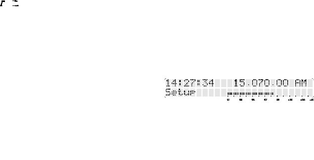
g. The receiver’s display is split into several different areas. The current FREQUENCY and MODE are always visible, but other information varies depending upon the operating condition and the menus selected. This illustration may be useful for reference.
1Auxiliary information (volume, squelch etc)
/keypad entry
2Receive frequency
3Reception mode
4Attenuator (A) or preamplifier (P) indicator
5Signal strength meter (S-meter)
6Squelch open / close indicator
7Fast tuning indicator
8Dial lock indicator
9Spin-wheel function
10 button function
11, 12, 13 Menu button functions
AR7030 OPERATING MANUAL |
PAGE 3 |
2-3 Quick reference guide Key
Buttons shown white on black are labelled on the front panel, for example |
|
Buttons shown black on grey are soft-keys labelled on the display, for example |
|
The spin-wheel is labelled on the display and shown with up/down arrows, for example |
Gain |
Soft keys shown with a bullet after the legend operate as toggles (on / off). The bullet shows the current state - solid for on and hollow for off.
Power
To turn the receiver on, press |
To turn the receiver off, press |
|
|
|
|
|
or |
|
|
|
|
||||
|
|
|
Display
To display the S-meter, press |
To display the clock press |
Filters
To change filter, press |
and use |
|
or |
Alternatively, cycle through filters with |
|
|
|
|
|
|
|||||||||||||
|
|
|
|
|
|
||||||||||||||||||
|
|||||||||||||||||||||||
|
|
|
|||||||||||||||||||||
To shift the filter passband, press |
|
|
|
|
|
|
|
|
and use |
PBS |
|
|
|
|
|
|
|
||||||
To adjust audio frequency in CW and DATA modes, press |
|
|
|
|
|
and use |
BFO |
||||||||||||||||
To adjust audio tone, press |
|
|
|
|
|
|
|
|
and then use |
Treb or |
|
|
Bass as required |
||||||||||
|
|
|
|
|
|
|
|
|
|||||||||||||||
RF and IF Gain
To adjust RF gain, press |
|
|
|
|
|
|
and use |
|
|
or |
|
|
for adjustment in 10dB steps |
||||
|
|
||||||||||||||||
|
|
|
|||||||||||||||
To adjust IF gain, press |
|
|
|
|
and use |
Gain (for RF and IF controls together) |
|||||||||||
OR press |
|
|
|
|
|
|
|
|
|
|
and use |
|
|
|
Gain (for IF gain with filter bandwidth) |
||
|
|
|
|
|
|
|
|
|
|
|
|
|
|||||
Squelch
To adjust squelch level, press |
|
|
and use |
Sql (for squelch with dual VFO) |
||||||||||||||
|
|
|||||||||||||||||
OR press |
|
|
|
|
|
|
|
|
and use |
|
Sql (for squelch with memory scan) |
|||||||
|
|
|
|
|
|
|
|
|
||||||||||
|
|
|
|
|
|
|
|
|
||||||||||
OR press |
|
|
|
|
|
and use |
Sql (in NFM mode for general listening) |
|||||||||||
With squelch active |
|
|
|
|
|
|
|
will mute the receiver’s audio with no signal, and |
|
|
|
will stop scanning if a |
||||||
|
|
|
|
|
|
|
|
|
|
|||||||||
|
|
|
|
|
|
|
|
|
||||||||||
signal is present |
|
|
|
|
|
|
|
|
|
|
|
|
|
|
|
|
||
Memories
To select and preview a memory, press |
and use |
Mxx |
To recall from a memory (into the VFO), press |
, use |
Mxx to preview then press |
To store into a memory (from the VFO), press |
, use |
Mxx to preview then press |
Scanning
To set scan speed, press |
|
|
|
|
|
|
|
|
|
|
|
|
|
|
|
|
|
|
|
|
|
|
|
|
|
and use |
|
|
|
|
|
|
Dly (for dual VFO scanning) |
|||||||||||||||||||
|
|
|
|
|
|
|
|
|
|
|
|
|
|
|
|
|
|
|
|
|
|
|
|
|
||||||||||||||||||||||||||||
OR press |
|
|
|
|
|
|
|
|
|
and use |
|
|
|
|
|
|
|
Dly (for memory scanning) |
|
|
|
|||||||||||||||||||||||||||||||
|
|
|
|
|
|
|
|
|
|
|
|
|||||||||||||||||||||||||||||||||||||||||
|
|
|
|
|
|
|
|
|
|
|
|
|||||||||||||||||||||||||||||||||||||||||
To scan the two VFOs, press |
|
|
|
|
|
|
|
|
|
|
|
|
|
|
|
|
|
|
|
|
|
|
|
|
|
|
|
|
|
|
|
|
|
|
|
|
|
|
|
|
|
|
||||||||||
|
|
|
|
|
|
|
|
|
|
|
|
|
|
|
|
|
|
|
|
|
|
|
|
|
|
|
|
|
|
|
|
|
|
|
|
|
|
|
|
|
|
|||||||||||
To scan memory channels, press |
|
|
|
|
|
|
|
|
|
|
|
|
|
|
|
|
|
|
|
|
|
|
|
|
|
|
|
|
|
|
|
|
|
|
|
|
|
|
|
|
|
|
||||||||||
To set memory block for scanning, press |
|
|
|
|
|
|
|
|
|
|
|
|
|
|
|
|
|
|
|
|
|
|
|
|
|
|
|
|
|
|
then use |
|
|
|
|
|
|
|
|
|
From |
|||||||||||
|
|
|
|
|
|
|
|
|
|
|
|
|
|
|
|
|
|
|
|
|
|
|
|
|
|
|
|
|
|
|
|
|||||||||||||||||||||
|
|
|
|
|
|
|
|
|
|
|
|
|
|
|
|
|
|
|
|
|
|
|
|
|
|
|
|
|
|
|
|
|
|
|
|
|
|
|
|
|
or |
|
|
|
|
|
To |
|||||
|
|
|
|
|
|
|
|
|
|
|
|
|
|
|
|
|
|
|
|
|
|
|
|
|
|
|
|
|
|
|
|
|
|
|
|
|
|
|
|
|
|
|
||||||||||
To exclude memories from scan, press |
|
|
|
|
|
|
|
|
|
|
|
|
|
|
|
, use |
|
|
|
|
Mxx to select then press |
|
|
|
||||||||||||||||||||||||||||
|
|
|
|
|
|
|
|
|
|
|
|
|
|
|
|
|
|
|
|
|
|
|||||||||||||||||||||||||||||||
|
|
|
|
|
|
|
|
|
|
|
|
|
|
|
|
|
|
|
|
|
|
|||||||||||||||||||||||||||||||
Clock and Timer
To set timer run time or sleep time, press |
|
|
|
|
|
and use |
Mins and |
|
|
|
|
|
|
|
|
|
|
|||||||||||||||||||||||||||||||||||||||||||
|
|
|
|
|
|
|
|
|
|
|
|
|
|
|||||||||||||||||||||||||||||||||||||||||||||||
To set timer start time, press |
|
|
|
|
|
|
|
|
|
|
|
|
|
|
|
|
|
|
|
|
|
|
|
|
|
|
|
and then use |
Hrs or |
|
|
|
|
|
|
|
|
|
|
|
|
|
|
|
Mins as required |
|||||||||||||||
|
|
|
|
|
|
|
|
|
|
|
|
|
|
|
|
|
|
|
|
|
|
|
|
|
|
|
|
|
|
|
|
|
||||||||||||||||||||||||||||
To set clock time, press |
|
|
|
|
|
|
|
|
|
|
|
|
|
|
|
|
|
|
|
|
|
|
|
|
|
|
|
and then use |
Hrs or |
|
|
|
|
|
|
|
|
|
Mins as required |
|||||||||||||||||||||
|
|
|
|
|
|
|
|
|
|
|
|
|
|
|
|
|
|
|
|
|
|
|
|
|
|
|
|
|
|
|
|
|
|
|
|
|
|
|
|
|
|
|
|
|||||||||||||||||
To start sleep mode countdown, press |
|
|
|
|
|
|
|
|
|
|
|
|
|
|
|
|
|
|
|
|
|
|
|
|
|
|
|
|
|
|
|
|
||||||||||||||||||||||||||||
|
|
|
|
|
|
|
|
|
|
|
|
|
|
|
|
|
|
|
|
|
|
|
|
|
|
|
|
|
|
|
|
|
|
|||||||||||||||||||||||||||
|
|
|
|
|
|
|
|
|
|
|
|
|
|
|
|
|
|
|
|
|
|
|
|
|
|
|
|
|
|
|
|
|
|
|||||||||||||||||||||||||||
To arm timer for switch-on, press |
|
|
|
|
|
|
|
|
|
|
|
|
|
|
|
|
|
|
|
|
|
|
|
|
|
|
|
|
|
|
|
|
||||||||||||||||||||||||||||
|
|
|
|
|
|
|
|
|
|
|
|
|
|
|
|
|
|
|
|
|
|
|
|
|
|
|
|
|
|
|
|
|
|
|
|
|
|
|
|
|
||||||||||||||||||||
|
|
|
|
|
|
|
|
|
|
|
|
|
|
|
|
|
|
|
|
|
|
|
|
|
|
|
|
|
|
|
|
|
|
|
|
|
|
|
|
|
||||||||||||||||||||
PAGE 4 AR7030 OPERATING MANUAL

2-4 Menu structure
AR7030 OPERATING MANUAL |
PAGE 5 |
2-5 Infrared remote controller - quick reference
Key
 Number key 0 through to 9
 Backspace key (deletes last numeric keypress)
 Clear key (deletes whole numeric entry)
All keys labelled + or - will auto-repeat if held pressed.
Tuning
To enter a frequency directly, press 


OR press 


Frequencies can have any number of digits, with or without a decimal point, up to a maximum of 9 characters. Resolution of entries can be to 1Hz, with the receiver rounding to the nearest tuning step.
Frequencies of 50kHz or less are taken as tuning step size, not as receiver frequency.
To tune the receiver in steps, press |
or |
(step size set as described above). |
To switch between active and background VFOs, press |
(VFO-A is copied to VFO-B if B is not already set). |
|
Volume
To change the volume setting, press |
or |
Mode
Mode key |
selects CW mode or NFM mode if CW is already selected. |
Mode key |
selects LSB mode or USB mode if LSB is already selected. |
Mode key |
selects AM mode or Sync mode if AM is already selected. |
Filters
To change the selected filter, press |
|
then |
or |
|
|
|
|
|
|
|
|
|
|
||||
|
|
|
|
|
||||
To move the filter passband, press |
|
then |
or |
|
|
To clear PBS offset, press |
||
|
|
|
||||||
|
|
|
||||||
To alter the audio tone, press |
or |
then |
|
|
or |
|
|
|
|
|
|
||||||
|
|
|
||||||
Memories
To select and preview a memory, press |
|
|
(one or two digits may be entered). |
|
||
To preview the currently selected memory, press |
|
|
|
|
|
|
To select next or previous memories, press |
or |
|
after |
or |
have been pressed. |
|
|
||||||
|
||||||
To select and recall a memory (into the VFO), press |
|
|
(one or two digits may be entered). |
|||
To recall the currently selected memory (into the VFO), press |
|
|
|
|||
To recall the next (and subsequent) memories (into the VFO), press |
. . |
. . |
etc. |
|||
To select a memory and store (from the VFO), press |
|
|
(one or two digits may be entered). |
|||
To store into the currently selected memory (from the VFO), press |
|
|
|
|||
PAGE 6 AR7030 OPERATING MANUAL
3 Major Features
The new AR7030 is the result of a combined project between AOR and internationally acclaimed UK designer John Thorpe. The AR7030 represents the very latest and best ever “JT” design concentrating on exceptional strong signal handling with enhanced microprocessor features and facilities. It is manufactured by AOR MANUFACTURING LTD based in Derbyshire, UK.
¬ Excellent strong signal handling
In Europe, especially at night, strong signal handling is of prime concern and this is where the AR7030 stands ahead of the field - offering an IP3 greater than +30dBm (typically +35dBm, reduced by about 10dB with the preamp switched on) and dynamic range greater than 100dB in AM mode with a 5.5 kHz filter and greater than 105dB in SSB mode with a 2.2 kHz filter. This fantastic strong signal handling is made possible by the innovative configuration of a lateral DMOS FET QUAD first mixer running at 15V, relay switching in the front end (instead of the more usual diodes) and the use of shielded inductors throughout the signal path.
¬ High sensitivity and selectivity
All this and great sensitivity - better than 0.5uV for 10dB S/N in AM mode and better than 0.3uV for 10dB S/N in SSB (with the preamp switched on). Selectivity too is razor sharp offering greater than 95dB @ 10kHz SSB and almost 110dB @ 20kHz.No other receiver in its class, nor indeed at a considerably higher price can match the sheer performance excellence of the AR7030.
¬ High Tech
The receiver is built around a TCXO frequency standard which provides the reference for all its circuitry, ensuring the ultimate in stability and optimum alignment. A single loop DDS system provides the clean local oscillator essential for low reciprocal mixing levels and seamless tuning in approximately 2.7Hz steps (no tuning “plops” at regular intervals). The receiver is a double conversion super heterodyne with intermediate frequencies of 45MHz and 455kHz.
The IF filters are self-aligned by the receiver using advanced microprocessor control, ensuring “spot on” alignment and symmetry of passband characteristics essential for serious ECSS listening. The main PCB will accept a number of different filters including various Murata types and Collins mechanical units, all will be self-aligned! The displayed filter bandwidths are not fixed but actually measured by the receiver permitting various displays such as 2.2kHz, 2.3kHz, 2.4kHz, 2.5kHz etc depending upon the particular filter fitted.
¬ Computer control port
Virtually every aspect of the AR7030 is controllable via the REMOTE port. The AR7030 may be connected directly to a host computer such as a PC (via RS232 link) with which, for example, frequency memories may be loaded, frequency and mode changed and signal activity logged - expanding the listening station even further.
¬All mode receive over a wide frequency range
All reception modes are available as standard: USB, LSB, CW, AM, Synchronous AM, NFM, DATA. The receive coverage is 0 - 32 MHz, the AR7030 has not been disabled below 150 or 30 kHz, or made insensitive in the mediumwave band. The standard fitted IF filters include: 2.2kHz, 5.5kHz, 7.0kHz and 10kHz with two additional positions available for CW or other filter options.
¬ Auto synchronous tuning
The receiver is capable of tuning itself automatically in synchronous AM mode using a new variable bandwidth synchronous detector. Simply select synchronous mode, tune the receiver to approximately the correct frequency so that intelligible audio can be heard and wait... within a few seconds the AR7030 will sample the frequency, tune to the carrier (its great watching it tune itself!) and lock solidly onto the station. Should you prefer, you may select fully manual operation of the synchronous detector.
¬ Pass band tuning
(even on synchronous AM)
Enhanced features include pass band tuning of approx ±4.2kHz, variable audio pitch on CW and DATA modes and an advanced, self tracking, synchronous detector for AM listening to eliminate the effects of transmitter or receiver drift as well as reducing distortion from selective fading. The pass band tuning may be used in synchronous AM mode to select synchronous USB, LSB, DSB or anything in between.
¬ Full AGC control plus IF gain
A specially developed AGC release characteristic produces outstanding SSB quality with quick recovery from strong signals and noise spikes. Gentle signal compression has also been included to reduce the audible effects of noise pulses. An IF gain control is available along with three AGC speeds and AGC defeat.
A built-in six level attenuator provides many levels of sensitivity:- +10dB, 0dB, -10dB, -20dB, -30dB and -40dB, however given the excellent strong signal handling of the AR7030 this is going to be a control rarely required! The receiver can automatically switch in the attenuator to keep incoming signals within its AGC range. Of course you may manually select attenuation should you prefer.
¬ Aerial input including whip amplifier
The rear panel of the AR7030 has inputs for a wire aerial with ground connection, 50 OHM SO239 connection plus selection of a high impedance whip amplifier which is fitted as standard.
¬ Audio output
Audio output is of high quality and clear tone when using the built-in top mounted speaker. A 3.5mm external speaker jack is provided on the rear panel which mutes
AR7030 OPERATING MANUAL |
PAGE 7 |
the internal speaker, the amplifier provides more than 2 WATTS of audio - there are even treble and bass controls. A stereo 3.5mm front panel socket provides headphone output from a separate internal stereo amplifier and may drive mono or stereo ‘phones. The auxiliary outputs (left and right) have separately adjustable levels and may be used to drive an external recorder or data decoders.
¬ Dot matrix LCD
A 48 character, rear illuminated dot matrix LCD with rear panel adjustable contrast provides a huge amount of information, a wide range accurate signal meter and text based menus.
¬ Assignable controls
Assignable controls enable you to place the functions YOU want at your fingertips - they retain the last used operation when the menus are removed, and include a press button
 and a spin-wheel
  .
.
¬ Infrared remote controller
A full featured 32 button infrared remote control is provided as standard and provides access to all commonly used facilities, including: tuning, volume, tone, memory functions, pass band shift and filter selection, as well as providing a numeric keypad for direct frequency entry.
TWO infrared sensors are employed, one on the front panel and one on the rear, so that the controller may be used from almost any position around the receiver.
¬ Stylish strong cabinet
The AR7030 features a custom CNC machined solid aluminium front panel with extruded aluminium shaped sides, metal top, bottom and rear panels. The front panel finish is brushed and anodised with the sides and other surfaces toned in a matching textured paint. Smooth curved lines, detailed panel breaks, top mounted domed speaker grille and ergonomically placed controls spell out the attention to detail of this robust, solid cabinet.
4 Precautions
4-1 Location
Do not use or leave the receiver in direct sunlight (especially the LCD). It is best to avoid locations where excessive heat, humidity, dust and vibration are expected. Always treat the receiver with care.
Take care to avoid spillage or leakage of liquids into the receiver and a.c. power supply. Special care should be taken to avoid liquid entering around the controls, through the speaker grille or via the connection jacks.
Avoid static discharge from aerial systems especially when using long wires - earth them to a central heating radiator or similar earthing point in order to discharge the wire before connection to the receiver. Always disconnect and earth any external aerial system if an electrical storm is expected.
Avoid a rapid disconnection then reconnection of the power supply. If disconnected, leave at least two seconds before reconnecting again. Ensure that all power connections are secure.
Avoid strong RF fields from nearby transmitters. If in doubt, disconnect the AR7030 from the aerial and switch the set off.
4-2 Looking after your receiver
Always keep the receiver free from dust and water. Use a soft, dry cloth to gently wipe the set clean. Never use abrasive cleaners or organic solvents which may damage certain parts.
4-3 Power requirements
The AR7030 is designed for operation from its supplied mains adapter. Operation is possible from a d.c. supply of 12 to 15V, which should be able to supply up to 800mA, but for full performance always power the receiver from 15V d.c rather than from 12V. (The receiver’s frequency coverage is not guaranteed above 30 MHz when operating from a 12V supply).
EMC NOTICE - This receiver may not fully comply with the E.C. EMC directive if operated from an external power source other than the supplied AC adapter.
The d.c. input socket uses a 2.1mm coaxial power connector, and a 14mm long plug is recommended. This connector is configured CENTRE POSITIVE, the chassis of the receiver is at negative ground. The low noise power supply provided is pre-wired and provides a regulated 15V d.c. output with suitable connectors being fitted as standard for the a.c. mains input and connection to the AR7030.
The AR7030 has a rear panel socket for connection of an RF earth, allowing a separate earth to be taken to a water pipe, central heating system radiator or external earth rod. If fitting a separate external earth rod, consider the implications carefully if your mains supply uses a Protective Multiple Earth (PME) system. If in doubt consult an expert electrician. Never earth to a gas pipe!
SAFETY NOTICE - Always disconnect the power supply from the a.c mains when not in use.
4-4 Aerial (antenna) connection
The AR7030 has two aerial inputs, selected by a rear panel switch, allowing three basic types of connection (the actual choice of suitable aerial is almost limitless).
1.50 OHM (unbalanced) SO239 socket for connection of dipoles, long wires with matching devices, active aerials, verticals, yagis etc.
2.WHIP may be selected to activate an impedance matching amplifier when a telescopic aerial or very short wire is fitted to the 50 OHM SO239 socket.
3.WIRE aerial input is used for connection of long wire or similar relatively high impedance aerial systems.
PAGE 8 AR7030 OPERATING MANUAL
5 Controls and functions Front panel
5-1 On/Off power switch 
This button, located in the upper left corner of the front panel, switches the set on and off and selects the SETUP menu for general configuration of the receiver and setting of the clock and timer facilities.
To switch the receiver on, connect a suitable power source and press the power switch for about one second.
To switch the receiver off, press the power switch  TWICE, or use the
 soft-key from the SETUP menu. When switched off, whilst the receiver is still connected to its adapter, the clock time display will continue with a dim backlight.
5-2 Liquid Crystal Display (LCD)
Display of operating condition is provided by a high contrast, green backlit, dot matrix LCD. Information includes frequency, mode, bandwidth etc. Menu legends for the controls beneath the display are also provided along with an accurate 70 segment signal strength meter (S-meter).
5-3 Main rotary tuning control - MAIN DIAL
The large rotary tuning control is prominently located to the right of the front panel. This control changes the received frequency up and down. Often referred to as the VFO (Variable Frequency Oscillator), a rather historic
name for a tuning mechanism, in this operating manual it is referred to as the MAIN DIAL.
The receiver tunes in a very smooth manner with increments as small as 2.655 Hz. Excellent tuning dynamics increase the rate of tuning depending upon how fast the tuning control is rotated and the mode of reception.
It is possible to electronically lock the main dial to prevent accidental tuning. A lock indication (reversed L) is displayed on the LCD in this case.
5-4 Fast tuning button 
FAST tuning increases the speed of tuning when using the main dial. The letter F is displayed after the kHz of the frequency display when fast tuning is selected - the button switches this mode on and off. If tuning in automatic synchronous AM, the fast tuning mode is cancelled automatically when the receiver samples frequency and locks onto the transmission.
5-5 Mode selection buttons
The mode selection buttons are located in the top right corner of the front panel. They select all of the available modes in sequence: Dat (data reception), CW, LSB, USB, AM, Snc (synchronous AM) and NFM, the sequence then repeating. The current mode is displayed to the right of the frequency readout on the LCD.
AR7030 OPERATING MANUAL |
PAGE 9 |
5-6 Volume control
The volume is adjusted by the rotary encoder located in the lower left of the front panel. The volume level is displayed as a percentage on the top left of the LCD whilst the control is turned. The range is 0% (minimum) to 96% (maximum).
Note: It is normal for very low level audio to emanate from the speaker even when the volume is at 0%, especially in NFM mode.
5-7 Spin-wheel 
This encoder is used to make selections from various menus and to change the values of receiver settings such as pass band shift (PBS), IF gain, squelch etc. The function of the spin-wheel at any instant is displayed above it on the LCD.
5-8 General button 
This button is used to make selections from menus as a soft-key. The assigned function is displayed above it on the LCD.
5-9 Memory menu button 
Initially used to choose the MEMORY menu for selection of memory channel, scan parameters and audio mute. It is also used as a soft-key to make selections from other menus.
Rear panel
5-10 RF and IF settings button 
Initially used to choose the RF gain / attenuator, IF gain and VFO selection menu. It is also used as a soft-key to make selections from other menus.
5-11 Filter menu button 
Initially used to choose the filter bandwidth display / selection menu along with pass band shift (PBS) and audio tone control. It is also used as a soft-key to make selections from other menus.
5-12 Headphone socket
This 3.5mm socket will provide output to either stereo or mono headphones, no switching is required. Connection to this socket disables the internal speaker and any speaker connected to the rear EXT LS socket. Headphones should be of a nominally low impedance around 8 to 200 OHMS.
5-13 Bail bar
The front of the receiver may be lifted up clear of the table top to allow easy access to the front panel controls and clear visibility of the LCD. Pull the bar forward to lift the front of the receiver upward, rubber cushions prevent slipping on a table top.
5-14 Internal speaker
The AR7030 is fitted with a top mounted loudspeaker which provides excellent audio reproduction under most conditions.
PAGE 10 AR7030 OPERATING MANUAL
5-15 Computer control socket
This accessory socket is used for connection to a computer via RS232 link.
The socket is a 5-pin / 240° DIN with the following connections:
Pin 1 External supply output available,
|
nominal 14V @ 100mA MAX |
Pin 2 |
RXD |
Pin 3 |
TXD |
Pin 4 |
No connection |
Pin 5 |
GROUND |
Connection to a PC should be as follows:
AR7030 |
PC 9-D |
PC 25-D |
pin 2 |
pin 3 |
pin 2 |
pin 3 |
pin 2 |
pin 3 |
pin 5 |
pin 5 |
pin 7 (GND) |
5-16 Auxiliary equipment socket
This accessory socket is used for connection to tape recorders and data decoders. Two audio outputs are provided unaffected by volume and tone settings. A mute input and a 455 kHz IF output are also present.
The socket is of an 8-pin DIN, circular configuration with pin 8 being at the centre. The connections are as follows:
Pin 1 MUTE - ground to mute the receiver (in conjunction with a transmitter)
Pin 2 GROUND
Pin 3 External supply output available, nominal 14V @ 100mA MAX
Pin 4 Auxiliary audio output (LEFT) 0-800mV from 1kohm
Pin 5 Auxiliary audio output (RIGHT) 0-800mV from 1kohm
Pin 6 Aux control relay contact A
(for tape recorder motor control) Pin 7 Aux control relay contact B
(for tape recorder motor control)
Pin 8 455 kHz IF output -20dBm / 50 ohms
The aux relay can only be used for low voltage control, NEVER
CONNECT MAINS TO THE AUX RELAY CONTACTS.
5-17 DC power input
This is a 2.1mm coaxial power socket designed to accept external d.c. input from an ac adapter. See section 4-3 for supply details.
5-18 External speaker output socket
This 3.5mm mono jack socket provides audio output to drive an external speaker unit. Connection to this socket automatically disables the internal speaker but not a headphone if connected to the front panel socket.
An external speaker should have a minimum 8 ohm impedance and power handling of 2 watts or greater.
5-19 Display contrast adjustment
This rotary control adjusts the LCD display contrast and viewing angle. Adjust this for optimum display readability - it may need re-adjusting if the viewing angle is changed or if there is a significant change in temperature. The normal control position will often be slightly less than fullyclockwise.
5-20 Ground (chassis) connection
Ground connection for an external RF earth. This often reduces noise.
5-21 Wire aerial connection
Connect a long wire aerial to this terminal.
5-22 Antenna selection switch
This slide switch is used to select the aerial connection and function: 50 OHM, WHIP or WIRE.
5-23 50 OHM aerial socket
50 OHM SO239 socket designed for connection to unbalanced 50 OHM aerials with coaxial feeders, or, with the selection switch in the WHIP position, a telescopic aerial.
AR7030 OPERATING MANUAL |
PAGE 11 |
 Loading...