

AOR AR8200 Operating Manual

Section 1
(1) AR8200 Index
(1) Index ............................................................................................................................ 1
1-1 Introduction .................................................................................................................. 5
1-2 Take care of your radio ................................................................................................ 5
1-3 Attention while operating ............................................................................................. 6
1-4 Accessories supplied ................................................................................................... 7
1-5 Controls & functions .....................................................................................................8
1-5-1 Keypad ..................................................................................................................... 9
1-5-2 Summary of keys ...................................................................................................... 10
1-5-3 Side panel ................................................................................................................. 15
1-6 Power supply and battery charging ............................................................................. 16
1-6-1 Internal batteries ....................................................................................................... 16
1-6-2 Charging the NiCads ................................................................................................ 18
1-6-3 Cigar lighter lead ...................................................................................................... 18
1-6-4 Battery considerations .............................................................................................. 19
(2) Making the AR8200 ready for operation ................................................................... 20
2-1 LCD (Liquid Crystal Display) ....................................................................................... 20
2-2 Connect the aerial (antenna) ....................................................................................... 21
2-3 Fit the batteries ............................................................................................................ 21
2-4 Keypad and knobs... what you need to know ‘most’ .................................................... 22
2-4-1 ENTER key ............................................................................................................... 22
2-4-2 FUNCTION key ......................................................................................................... 22
2-4-3 PASS key .................................................................................................................. 22
2-4-4 CLEAR key ............................................................................................................... 23
2-4-5 MONITOR key .......................................................................................................... 23
2-4-6 KEY lock ................................................................................................................... 23
(3) Basic manual operation of the receiver .................................................................... 24
3-1 Switching On ............................................................................................................... 24
3-2 2VFO twin VFO selection ............................................................................................ 24
3-3 Entering a frequency using the numeric keypad ......................................................... 26
3-4 Correcting frequency input .......................................................................................... 27
3-5 Changing frequency using the ñ and ò keys .............................................................. 28
3-6 Changing frequency using the main dial ..................................................................... 28
3-7 Changing receive mode ............................................................................................... 29
3-7-1 Auto-mode selection ................................................................................................. 29
3-7-2 Receive mode selection menu ................................................................................. 29
3-8 Changing tuning STEP size ......................................................................................... 31
3-9 STEP-adjust ................................................................................................................ 33
3-9-1 Automatic calculation of step adjust ......................................................................... 33
3-9-2 Cancelling step adjust .............................................................................................. 34
3-9-3 Manual setting of step adjust .................................................................................... 34
3-10 FREQUENCY OFFSET .............................................................................................. 36
3-10-1 Using pre-programmed frequency offset data ........................................................ 36
3-10-2 Entering new frequency offset data ........................................................................ 37
3-11 Attenuator .................................................................................................................. 38
3-12 Noise limiter ............................................................................................................... 38
3-13 AFC - Automatic Frequency Control .......................................................................... 39
(4) VFO enhanced facilities ............................................................................................. 41
4-1 Quick memories ...........................................................................................................41
4-1-1 Saving quick memory data ....................................................................................... 41
4-1-2 Recalling quick memories ........................................................................................ 42
4-2 VFO scan .................................................................................................................... 42
4-2-1 VFO SCAN sampling time ........................................................................................ 43
4-3 VFO Search ................................................................................................................. 43
4-3-1 Defining VFO search ................................................................................................ 43
1

4-3-2 Starting VFO search ................................................................................................. 43
4-3-3 Forcing VFO search to resume & changing search direction ................................... 44
4-3-4 Locking out unwanted frequencies (PASS) .............................................................. 44
4-3-5 Saving active frequencies to memory ...................................................................... 45
4-3-6 Exiting VFO search .................................................................................................. 46
4-4 VFO environment menu .............................................................................................. 46
4-4-1 VFO SCAN ...............................................................................................................46
4-4-2 VFO search DELAY environment ............................................................................. 46
4-4-3 VFO search LEVEL squelch environment ................................................................ 47
4-4-4 VFO search VOICE squelch environment ................................................................ 48
4-4-5 VFO FREE search environment ............................................................................... 48
4-4-6 VFO AUTO STORE environment ............................................................................. 49
4-4-7 VFO DELETE bank “J” environment ......................................................................... 49
4-4-8 VFO QUICK MEMORY environment ........................................................................ 50
(5) Memory channels & banks ........................................................................................ 51
5-1 Memory channel overview ........................................................................................... 51
5-2 Storing VFO frequencies & data into memory ............................................................. 52
5-2-1 Another example of memory write ............................................................................ 54
5-2-2 Automatic memory allocation ................................................................................... 55
5-3 Memory write protect ................................................................................................... 55
5-4 Memory read “M.RD” ................................................................................................... 56
5-4-1 Memory channel review / hunt ................................................................................. 57
5-5 Deleting memory channels .......................................................................................... 57
5-5-1 Memory channel editing ........................................................................................... 58
5-5-2 Adding text names to memory banks ....................................................................... 58
5-6 Transfer of memory channel to VFO ........................................................................... 58
5-7 Dynamic memory bank resizing .................................................................................. 58
(6) Priority operation ........................................................................................................ 59
6-1 Engaging PRIORITY channel ...................................................................................... 60
6-2 Changing PRIORITY channel data .............................................................................. 60
6-2-1 Changing the priority channel data pickup channel .................................................. 61
6-2-2 Changing priority interval time .................................................................................. 61
(7) SCAN - scanning memory channels & banks .......................................................... 62
7-1 SCAN - outline introduction ......................................................................................... 62
7-2 SCAN considerations .................................................................................................. 62
7-3 Starting to SCAN .........................................................................................................63
7-3-1 Transfer of active memory to VFO ........................................................................... 64
7-4 Selecting a scan bank ................................................................................................. 64
7-5 Channel PASS .............................................................................................................64
7-5-1 Toggling memory channel PASS .............................................................................. 65
7-5-2 Removing ALL memory PASS tags in one go .......................................................... 65
7-6 Deleting memory channels .......................................................................................... 66
7-6-1 Deleting single memory channels ............................................................................ 66
7-6-2 Deleting whole memory banks in one go .................................................................. 66
7-7 Scan bank link (scan group) ........................................................................................ 66
7-8 Additional scan facilities ...............................................................................................67
7-8-1 Scan DELAY .............................................................................................................68
7-8-2 Scan LEVEL .............................................................................................................68
7-8-3 Scan VOICE .............................................................................................................69
7-8-4 Scan FREE ............................................................................................................... 70
7-8-5 Scan (receive) MODE .............................................................................................. 70
7-8-6 Write protect of memory channels & banks .............................................................. 71
7-9 Select scan .................................................................................................................. 71
7-9-1 Adding select scan channels in memory read .......................................................... 71
7-9-2 Starting / stopping select scan ................................................................................ 71
7-9-3 Select scan environment .......................................................................................... 72
2

7-9-4 Editing the contents of the select scan list ............................................................... 72
7-9-5 Deleting all select scan channels ............................................................................. 73
(8) Search mode ............................................................................................................... 74
8-1 Search types ................................................................................................................ 74
8-1-1 Program search overview ......................................................................................... 74
8-2 Starting program search .............................................................................................. 75
8-2-1 Reversing the direction of search ............................................................................. 75
8-2-2 Forcing the search to resume ................................................................................... 75
8-2-3 Stopping the search ................................................................................................. 75
8-2-4 Copying an active frequency to the VFO or memory location .................................. 76
8-3 Selection of search bank ............................................................................................. 76
8-4 Programming a search bank ....................................................................................... 78
8-5 Locking out unwanted active frequencies (PASS) ...................................................... 80
8-5-1 Search pass menu ................................................................................................... 80
8-6 Search bank link .......................................................................................................... 81
8-7 Additional search facilities ........................................................................................... 82
8-7-1 Search DELAY ......................................................................................................... 83
8-7-2 Search LEVEL .......................................................................................................... 84
8-7-3 Search VOICE .......................................................................................................... 84
8-7-4 Search FREE ............................................................................................................85
8-7-5 AUTO STORE .......................................................................................................... 86
8-7-6 DELETE bank “J” ..................................................................................................... 86
8-7-7 Deleting search banks .............................................................................................. 87
8-7-8 Write protect and copying search banks .................................................................. 87
(9) EDIT menu ................................................................................................................... 88
9-1 EDIT COPY memory channel ...................................................................................... 88
9-2 EDIT COPY memory bank ........................................................................................... 89
9-3 EDIT COPY search bank ............................................................................................. 90
9-4 EDIT MOVE memory channel ...................................................................................... 90
9-5 EDIT SWAP memory channel ..................................................................................... 91
9-6 EDIT memory channel ................................................................................................. 92
9-7 EDIT Search protect .................................................................................................... 93
(10) DELETE menu facilities ............................................................................................ 94
10-1 DELETE search banks and search PASS frequencies ............................................. 94
10-2 DELETE VFO PASS .................................................................................................. 95
10-3 DELETE memory bank .............................................................................................. 95
10-4 DELETE select scan channels .................................................................................. 96
10-5 DELETE memory channel protect ............................................................................. 96
10-6 DELETE memory channel pass ................................................................................ 97
(11) Write protect ............................................................................................................. 98
11-1 Memory CHANNEL write protect ............................................................................... 98
11-2 Write protect during memory input ............................................................................ 98
11-3 Channel protect status for existing memory channels ............................................... 98
11-4 Channel protect delete ............................................................................................... 99
11-5 Memory BANK write protect ...................................................................................... 99
11-6 Search bank write protect .......................................................................................... 100
11-7 Global write protect .................................................................................................... 100
(12) TEXT search and input ............................................................................................. 101
12-1 Text input menus ....................................................................................................... 101
12-2 Text search ................................................................................................................ 102
(13) SHORT CUT keys ...................................................................................................... 103
13-1 Short cut menu access .............................................................................................. 103
13-2 Short cut text entry .................................................................................................... 104
13-3 Short cut text entry, keypad with ïðñò keys .......................................................... 105
3

(14) Configuration menu ................................................................................................. 106
14-1 CONFIG BEEP .......................................................................................................... 106
14-2 CONFIG LAMP .......................................................................................................... 106
14-3 CONFIG CONTRAST ................................................................................................ 107
14-4 CONFIG Power save ................................................................................................. 108
14-5 CONFIG Auto power off ............................................................................................. 109
14-6 CONFIG REMOTE BPS ............................................................................................. 109
14-7 CONFIG FREQ DISP ................................................................................................. 110
14-8 CONFIG GLOBAL write protect ................................................................................. 110
14-9 CONFIG Opening message ...................................................................................... 111
(15) Band scope ............................................................................................................... 112
15-1 Starting the band scope ............................................................................................. 112
15-2 Exit from band scope ................................................................................................. 11 3
15-3 Setting frequency span width (waveform enlargement) ............................................ 113
15-4 Moving the marker ..................................................................................................... 113
15-5 Marker to strongest signal (peak search) .................................................................. 113
15-6 Entering a new centre frequency ............................................................................... 114
15-7 Transfer of marker frequency to VFO ........................................................................ 114
15-8 Peak hold ................................................................................................................... 114
15-9 Saving active trace to memory .................................................................................. 114
15-10 Loading stored band scope traces from memory .................................................... 115
(16) Sleep .......................................................................................................................... 116
(17) Option socket ............................................................................................................ 117
17-1 RS232 operation ........................................................................................................ 118
17-2 CLONE of data via the option socket ......................................................................... 118
17-2-1 How to clone data ................................................................................................... 119
(18) Slot card socket ........................................................................................................ 121
18-1 Optional slot cards ..................................................................................................... 121
18-1-1 Fitting the slot card ................................................................................................. 121
18-1-2 Removing the slot card ........................................................................................... 122
18-2 VI8200 optional voice inverter slot card ..................................................................... 122
18-3 CT8200 optional CTCSS slot card ............................................................................. 123
18-3-1 CTCSS tone squelch .............................................................................................. 123
18-3-2 CTCSS search ........................................................................................................ 124
18-4 TE8200 optional tone eliminator slot card ................................................................. 125
18-5 RU8200 optional record & playback slot card ............................................................ 126
18-5-1 Recording ............................................................................................................... 126
18-5-2 Playback ................................................................................................................. 127
18-6 EM8200 optional external extended memory slot card .............................................. 127
18-6-1 Initialising (formatting) the EM8200 before use ...................................................... 128
18-6-2 EM8200 ALL-DATA save and load ......................................................................... 129
18-6-3 EM8200 ALL-MEM save and load .......................................................................... 130
18-6-4 EM8200 MEMORY BANK save and load ............................................................... 131
18-6-5 EM8200 ALL-SRCH save and load ........................................................................ 132
18-6-6 EM8200 SEARCH BANK save and load ................................................................ 132
18-6-7 EM8200 internally stored band scope save and load .............................................. 133
(19) Trouble shooting ....................................................................................................... 136
19-1 Soft reset of microprocessor ...................................................................................... 136
19-2 Other trouble shooting suggestions ........................................................................... 136
19-3 Trouble shooting - Take note of the following ............................................................ 137
(20) Optional accessories ................................................................................................ 138
(21) Aerial (antenna), earths & propagation ................................................................... 139
(22) Specification ............................................................................................................. 140
4

Section 1-1, 1-2
1-1 Introduction
Thank you for purchasing the AR8200 hand held wide band all mode receiver. The AR8200 is designed
using the very latest technology to ensure the highest levels of performance and reliability. To get the
best possible results from your AR8200 we recommend that you read this manual and familiarise
yourself with the receiver. Although carefully designed, this receiver (like all receivers) suffers from a
degree of internal noises known as spurii. They are a product of the receiver’s circuitry and do not
represent a fault. Apparent faults may be due to accidental misoperation of the receiver, if you think
there is a problem, carefully read all of the manual before deciding to contact your equipment supplier for
advice.
It is acknowledged that sections of this manual are repetitive, this is to enable the manual to be used as
a reference book (you don’t have to read it all from cover to cover in one go). Due to the international
nature of the product, some graphics contain Japanese characters.
Every effort has been made to make this manual correct and up to date. Due to continuous
development of the receiver and by error or omission anomalies may be found and this is
acknowledged.
© This manual is protected by copyright AOR Ltd 1998. No information contained in this manual may be
copied or transferred by any means without the prior written consent of AOR Ltd. AOR and the AOR
logo are trade marks of AOR Ltd. All other trade marks and names are acknowledged. E&OE
1-2 Take care of your radio
There are no internal operator adjustments. In the unlikely event of servicing being required, please
contact your dealer for technical assistance.
Do not use or leave the receiver in direct sunlight (especially the LCD). It is best to avoid locations
where excessive heat, humidity, dust and vibration are expected. Always keep the AR8200 free from
dust and moisture. Use a soft, dry cloth to gently wipe the set clean, never use abrasive cleaners or
organic solvents which may damage certain parts. Treat the AR8200 with care, avoid spillage or leakage
of liquids into the receiver and a.c. charger. Special care should be taken to avoid liquid entering around
the controls, through the speaker grille or via the connection jacks.
The AR8200 is designed for operation from internal batteries or from its supplied a.c.-to-d.c. charger.
Operation is possible from any good quality regulated d.c. supply of 12 to 14V, which should be capable
of supplying 300mA. Never connect the AR8200 directly to the a.c. supply.
The d.c. input socket uses a mini 1.3mm power connector. This connector is configured CENTRE
POSITIVE, the chassis of the receiver is at negative ground. The charger supplied is pre-wired and
provides a nominal 12V d.c. output with suitable connectors being fitted as standard for the a.c. power
input and connection to the AR8200.
SAFETY NOTICE - Always disconnect the charger from the a.c. socket when not in use.
If using the AR8200 in a base station situation, the best short wave reception is usually achieved by the
fitting of a separate external earth rod, however consider the implications carefully if your a.c. building
supply uses a Protective Multiple Earth (PME) system. If in doubt consult an expert electrician. Never
earth to a gas pipe!
The AR8200 has a single BNC aerial socket for all frequencies. This is intended for connection to its
supplied whip aerial or a 50 OHM (unbalanced) coaxial fed aerial such as a discone, dipole, unipole,
yagis etc. When sighting the aerial, avoid power cables.
5

Section 1-2, 1-3
Operating anomalies
Should the AR8200 appear to behave strangely, normal operation may be easily achieved by resetting
the microprocessor. Two scenarios may be encountered due to power transients etc:
1.
Symptom:
Action:
remove one NiCad battery and count to thirty! Re-fit the battery and press the power
switch again. Normal operation should be restored but the last used frequency will be
lost, the AR8200 will restore the last but one frequency to display.
2. Symptom: The AR8200 fails to power up.
Action: Try the suggestion given in (1) then hold the key while powering up
the AR8200 to ‘Soft reset’ the microprocessor.
LCD remains on, no control of the keypad.
Remove any connection to external power such as the charger or cigar lead,
1-3 Attention while operating
1. Certain key operations are acted upon when the key is RELEASED, not while it is pressed. Allow
time for the AR8200 to register such actions before pressing another key.
2. The keylock is intentionally made to be
To release keylock, the key has to be held for more than one second, the key legend on the
LCD confirms operation. The key is disabled during keying sequences (such as when
entering frequencies).
3. If a key sequence is not completed, the microprocessor will automatically abort most operations
after about 90 seconds of keypad inactivity.
4. Currently displayed VFO data is saved at power down (to increase speed of operation and to
reduce write cycles). For this reason, if the AR8200 is powered down by removing external supply
(without internal batteries in place or when the batteries become exhausted), the last displayed
frequency will be lost and the frequency used prior to this will be displayed when next powered up.
Terminology - Search & Scan
If you have not used a wide range monitor before or are not familiar with the terminology used, it is very
important to understand the difference between SEARCH and SCAN modes.
SEARCH: The AR8200 provides several operations where transmissions (active frequencies) may
be automatically located by sweeping the receiver over a wide frequency range, either from the
currently displayed frequency travelling upwards (or downwards) in a specified tuning increment
(step) or by sweeping over-and-over between two specified frequency limits. This process is known
as SEARCHING, as the title implies, it can take a long time to find transmissions due to their ‘often
intermittent’ and brief nature. For this reason it is best to slice large frequency ranges into smaller,
more manageable pieces where they may be intensively studied. When examining large frequency
bands, it is common to find that 90% of frequencies are inactive and only a small number of the
remaining constitute what you really want. Searching still remains the best way to initially locate
active and interesting transmissions (in conjunction with a good frequency listing and band plan).
SCAN: Once active transmissions have been identified (either by searching or by using a good
frequency guide), it is more efficient to store the data into memories which can be rapidly and
automatically monitored in succession stopping when activity is encountered. This forms a much
difficult to operate
to prevent accidental operation.
6
Section 1-3, 1-4
more efficient means of monitoring the most wanted frequencies as you have targeted 100% what
you most want to hear, by contrast searching is very inefficient for day-to-day monitoring.
&Note:
search & scan facilities to operate.
active frequency when the squelch opens and “S” ‘squelch open’ legend is displayed to the left
of the signal meter. Advance the squelch control clockwise until the background noise is just
cancelled, this is known as the threshold position. If the squelch control is advanced too far,
weaker signals may be missed.
It is very important that the squelch is advanced to cancel background noise for the
This is because the AR8200 believes that it has found an
No noise and no “S” legend (with squelch advanced clockwise passed
threshold) = squelch closed.
Signal received or ‘noise’ emanating from speaker (squelch fully anti-clockwise, below
threshold) with no “S” legend = squelch open.
1-4 Accessories supplied
The following items are provided in the carton box:
1 x AR8200 receiver
1 x Whip aerial in BNC connector
1 x Medium Wave (MW) bar aerial
4 x AA NiCad batteries
1 x Charger (may be supplied in a separate cartons in some world market areas)
1 x Cigar adapter lead (containing internal 1A fuse)
1 x Hand strap
1 x Belt hook with two screws
1 x Operating manual (this booklet)
How to fit the hand strap
The hand strap anchor is located on the right hand side of the
AR8200 cabinet. The hand strap comprises of two loops, one
large and one small. Feed the small loop through the anchor
then feed the large loop through the small loop and gently pull
until tight. This strap is designed to be looped over your wrist
to prevent the AR8200 from contacting the ground if
accidentally dropped, it is not intended as a hard wearing
utility… do not swing the set or abuse the set using this
hand strap.
The MW bar also has a fixing hole so that you may tie it
down to prevent loss.
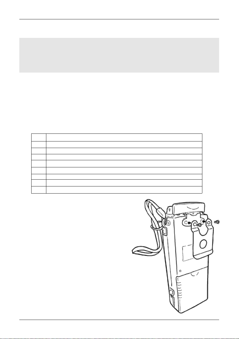
How to fit the belt hook
The belt hook is a shaped metal plate with two fixing holes on the top
edge, two fixing screws are provided. Do not use any other screws…
if you attempt to use longer screws, the internal parts may be permanently
damaged rendering the AR8200 inoperative. Offer the belt hook to the rear
of the AR8200, locate and align the fixing holes then carefully fit the two
supplied screws, fit both screws before tightening with a cross-head
screwdriver.
7
Section 1-5
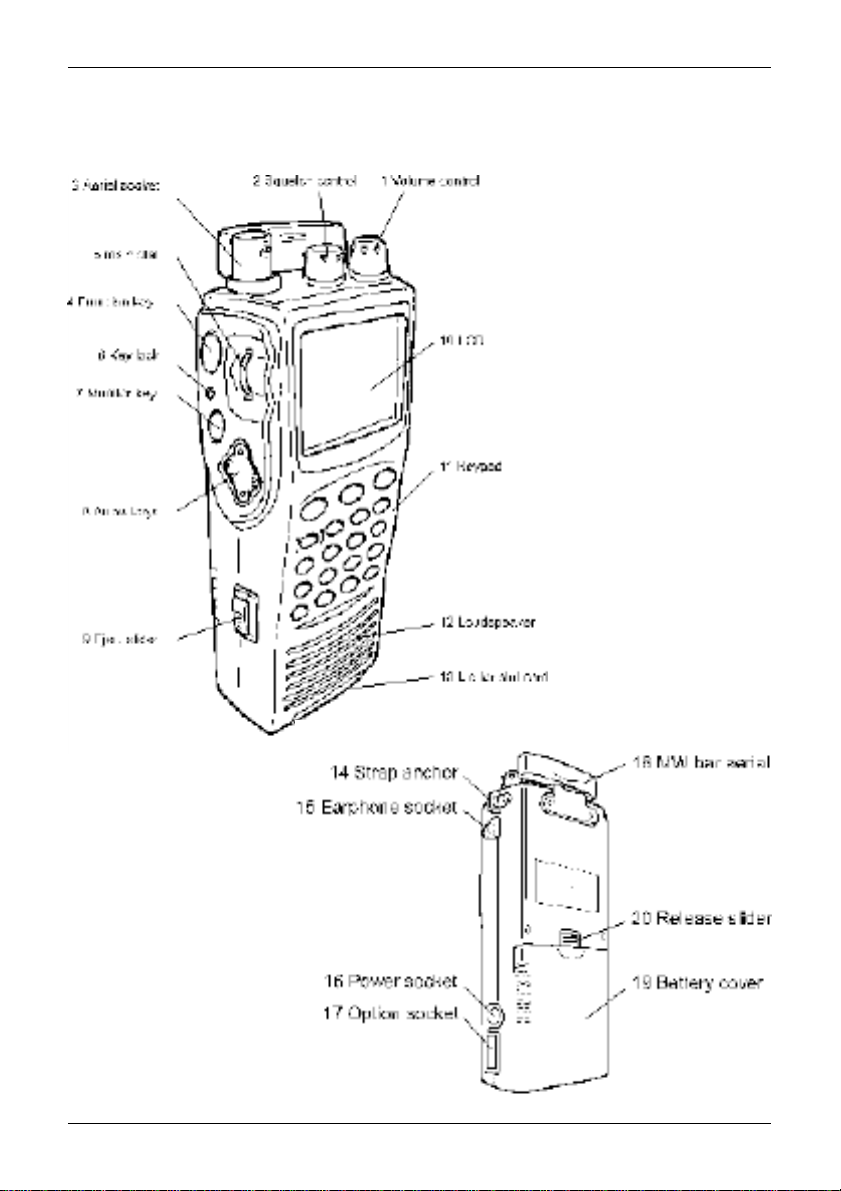
1-5 Controls & functions
Controls are located on the top, front and left hand side of the AR8200, a brief identification
is given here:
1. Rotary volume control
2. Rotary squelch control
3. BNC aerial socket
4. Function key
5. Main dial (thumb rotary)
6. Key Lock key
7. Monitor key
8. Arrow keys
9. Eject slider for optional SLOT CARD
10. LCD (Liquid Crystal Display)
11. Keypad
12. Loudspeaker
13. Lid for optional SLOT CARD
14. Hand strap anchor
15. Earphone / external speaker socket
16. External power / charging socket
17. Option socket
18. Medium Wave (MW) bar aerial
19. Battery compartment cover
20. Battery compartment release slider
8
Section 1-5-1
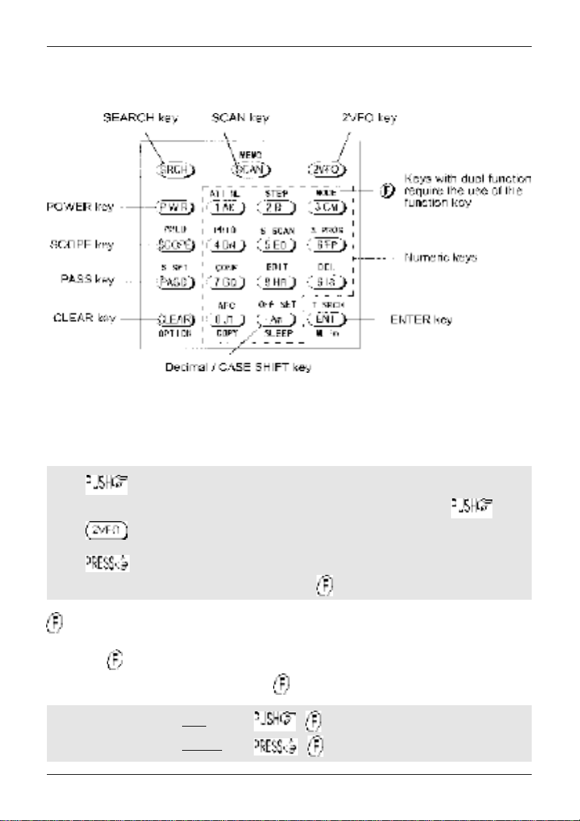
1-5-1 Keypad
Keypad conventions
Most keys have multiple functions, their functions are printed on the cabinet. However due the
restriction of available size, not all facilities can be shown on the keypad printing. To ease access to
the many facilities, two formats are employed:-
Push and release the key quickly to access the required facility. This applies to
primary facilities of keys such as numeric 1, 2, 3 etc. Also for example, quickly the
key while in 2VFO mode to toggle between the two VFOs VFO-A and VFO-B.
Press and HOLD the key for more than one second to access the second
function, sometimes this is in conjunction with the key.
Function key manipulation
The key also may be used by PUSH and PRESS depending upon the specific
requirement, in most cases however the key will require a simple PUSH.
“FUNC” LCD legend
“FUNC” LCD legend
solid
flashing
=
=
9
Section 1-5-2
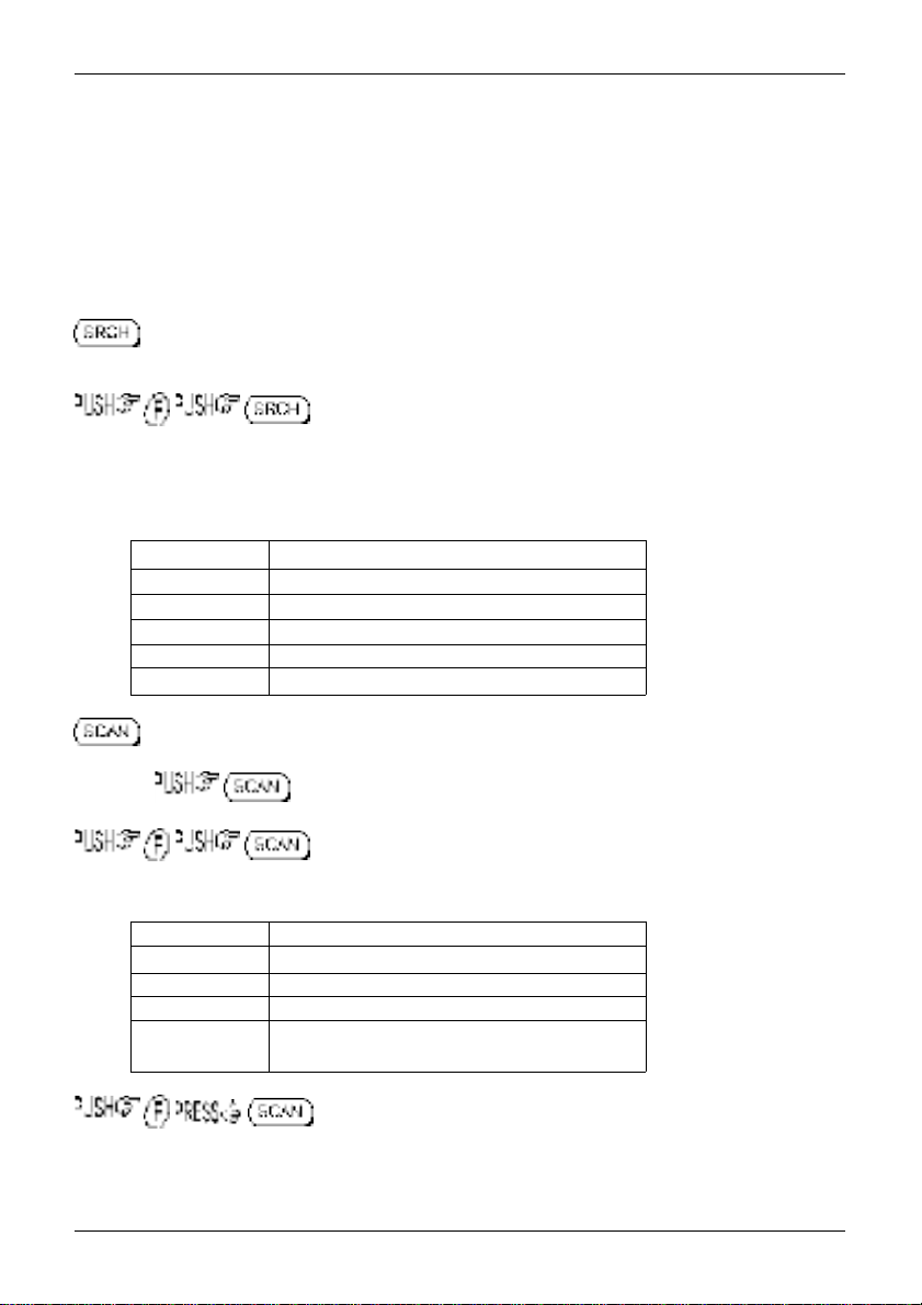
1-5-2 Summary of keys
The main keypad is located on the front cabinet of the AR8200 with other keys located on the left
hand side. When powered from internal batteries with the lamp configured to AUTO, the lamp will
automatically illuminate when keys are pressed and will stay illuminated for five seconds after the last
key press.
An optional CC8200 RS232 lead is required for computer control, the optional CO8200 lead is required
for copying data between two AR8200 radios, various optional SLOT CARDS are available which further
extend the AR8200 facilities (and menus).
PUSH this key to place the AR8200 into SEARCH mode, the LCD “SRCH” legend confirms operation.
to access the bank link menu where up to ten different selections of
linked search banks may be grouped, this is useful where a large frequency band has been split up into
smaller more manageable sizes for close scrutiny.
Additional search related parameters may be set up to optimise each search group independently using
this menu:-
DELAY OFF / HOLD / 0.1s to 9.9s (default = OFF)
LEVEL OFF / 1 to 255 (default = OFF)
VOICE OFF / 1 to 255 (default = OFF)
FREE OFF / 1s to 60s (default = OFF)
AUTOSTORE ON / OFF (default = OFF)
DELETE J (deletes the current data from bank J)
PUSH this key to place the AR8200 into MEMORY READ mode, the LCD legend “M.RD” confirms
selection. again to initiate SCAN, the LCD legend “SCAN” confirms selection
to access the bank link menu where up to ten groups of memories may
be selected to be scanned in succession, effectively forming one large scan bank. Additional scan
related parameters may be set up to optimise each scan group independently using this menu:-
DELAY OFF / HOLD / 0.1s to 9.9s (default = OFF)
LEVEL OFF / 1 to 255 (default = OFF)
VOICE OFF / 1 to 255 (default = OFF)
FREE OFF / 1s to 60s (default = OFF)
MODE SCAN ALL / WFM / NFM / SFM / WAM / AM
/ NAM / USB / LSB / CW (default = ALL)
to set the ratio of bank size between memory channels sharing a
common letter in upper and lower case.
10
Section 1-5-2
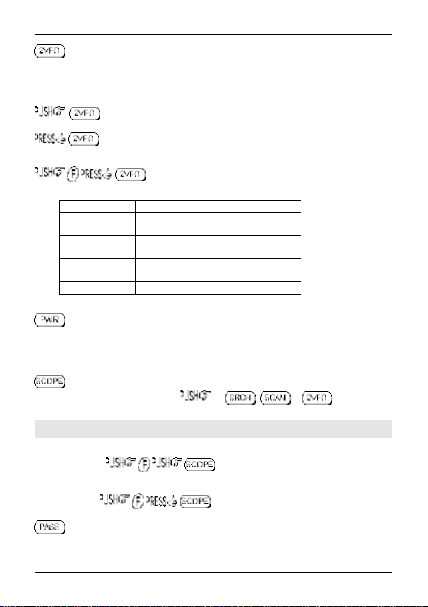
PUSH this key to place the AR8200 into 2VFO mode where you may receive spot frequencies and
‘generally monitor activity’. The LCD displays two lines of frequency readout, the upper (larger) being the
current receive frequency. The LCD legend “2VFO” confirms selection with each VFO being identified as
“V-A” and “V-B”.
again to toggle between VFO-A “V-A” and VFO-B “V-B”.
to initiate VFO search between the two displayed frequency limits set by VFO-A and
VFO-B, the legend “V-SR” confirms selection of VFO SEARCH.
to access the VFO MODE select menu where the following parameters
may be configured:-
VFO SCAN ON / OFF (default = OFF)
DELAY OFF / HOLD / 0.1s to 9.9s (default = OFF)
LEVEL OFF / 1 to 255 (default = OFF)
VOICE OFF / 1 to 255 (default = OFF)
FREE OFF / 1s to 60s (default = OFF)
AUTOSTORE ON / OFF (default = OFF)
DELETE J (deletes the current data from bank J)
QUICK MEMORY OFF / 10s to 990s (default = OFF)
PRESS this key to switch the AR8200 on and off as a toggle. To prevent accidental switch on and off,
the power key is placed between two ridges and has to be held for more than one second for the press to
be registered. The ridges also help location of the power key when operated in areas of low level
lighting.
PUSH this key to activate the band scope, the , or key to return to
normal operation.
&Note: Priority operation is disabled when the band scope facility is in use.
Traces will be overwritten as the band scope is written from left to right on the LCD. To build up a long
term activity display, to toggle the PEAK HOLD facility on / off, the LCD
legend “HLD” confirms operation.
The key sequence recalls a previously saved band scope trace.
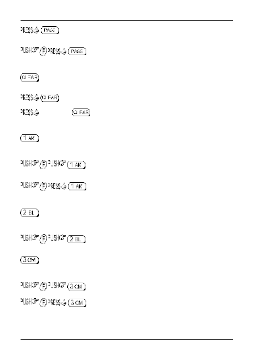
PUSH this key to PASS (lockout) memory channels during memory read & scan mode and to PASS
(skip) unwanted frequencies in search mode. Also acts as select ON/OFF/DEFAULT toggle in various
menus.
11
Section 1-5-2
in 2VFO mode to access the VFO PASS menu which extends to include the
SEARCH bank pass edit menu.
in 2VFO, SEARCH or SCAN mode to access the SELECT SCAN edit
menu.
PUSH to abort entry via the keypad.
to select the optional SLOT CARD when fitted.
and HOLD the key while powering On the AR8200 to soft reset the microprocessor
should the AR8200 appear to behave strangely... no memory contents will be lost.
Numeric figure one during frequency input. Selection of memory/scan bank “A” or “a” and search bank
“A” or “a” or “K” or “k”.
to toggle the attenuator on / off, the LCD legend “ATT” confirms
operation.
to toggle the noise limiter on / off, the LCD legend “NL ” confirms
operation.
Numeric figure two during frequency input. Selection of memory/scan bank “B” or “b” and search bank
“B” or “b” or “L” or “l”.
to access the tuning STEP size (increment) menu.
Numeric figure three during frequency input. Selection of memory/scan bank “C” or “c” and search bank
“C” or “c” or “M” or “m”.
to access the receive mode selection menu.
to select AUTO-MODE where the receiver mode and tuning step are
automatically selected by the AR8200 microprocessor from the pre-programmed band plan data (this is
a short cut to save using the receive mode menu). The LCD legend “AUT” confirms that auto-mode is
in operation.
12
Section 1-5-2
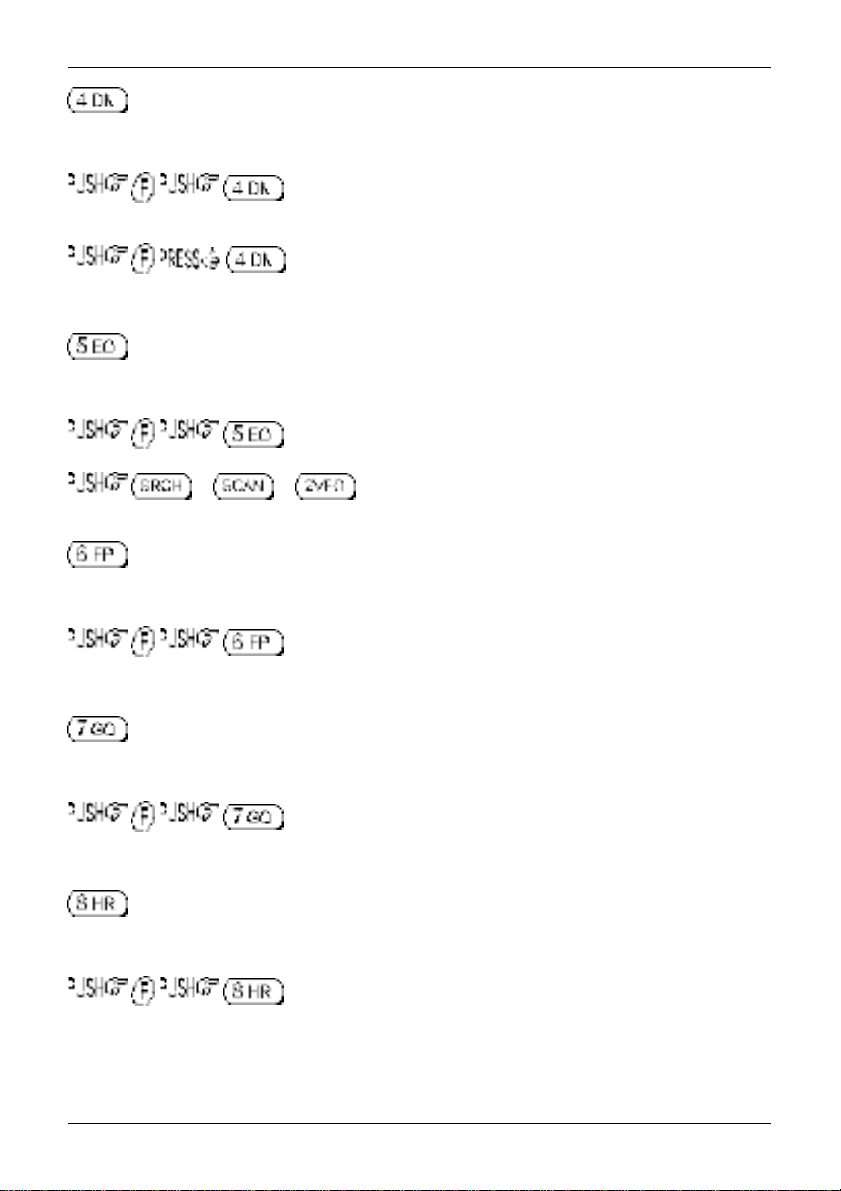
Numeric figure four during frequency input. Selection of memory/scan bank “D” or “d” and search bank
“D” or “d” or “N” or “n”.
toggles the priority facility on/off (assuming that one has already been
assigned using the priority menu). The LCD legend “PRI” confirms when priority has been selected.
to access the priority menu where the data from a memory channel may
be assigned for priority use. The interval sampling time may also be specified.
Numeric figure five during frequency input. Selection of memory/scan bank “E” or “e” and search bank
“E” or “e” or “O” or “o”.
to initiate select scan (assuming that more than one memory channel
has already been tagged for select scan). The LCD legend “SEL” indicates when select scan is active.
or or to exit select scan.
Numeric figure six during frequency input. Selection of memory/scan bank “F” or “f” and search bank “F”
or “f” or “P” or “p”.
to access the program search menu where upper / lower frequency
limits etc for search mode may be entered.
Numeric figure seven during frequency input. Selection of memory/scan bank “G” or “g” and search bank
“G” or “g” or “Q” or “q”.
to access the configuration menu where the beep, lamp, LCD contrast,
RS232 etc. may be configured.
Numeric figure eight during frequency input. Selection of memory/scan bank “H” or “h” and search bank
“H” or “h” or “R” or “r”.
to access the edit menu when memory channels and search banks may
be amended and copy protection configured.
13
Section 1-5-2
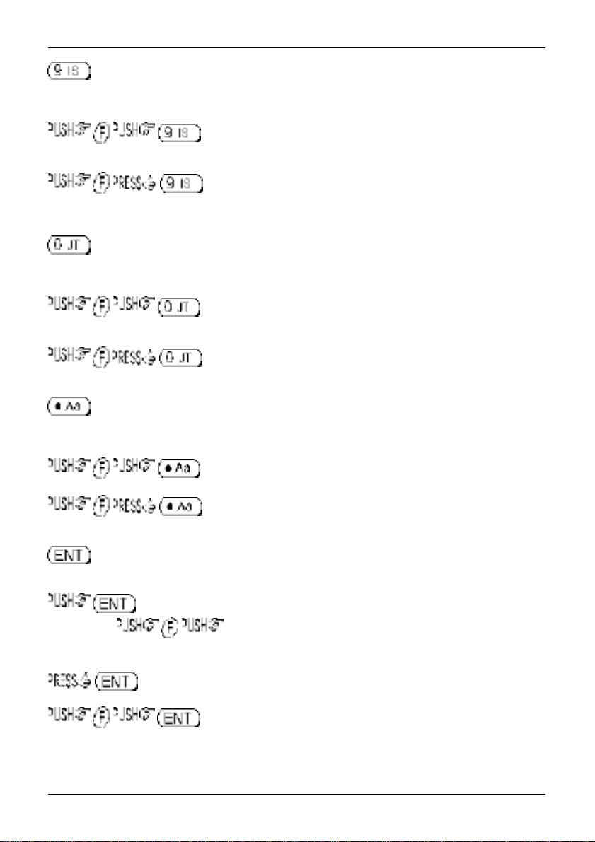
Numeric figure nine during frequency input. Selection of memory/scan bank “I” or “i” and search bank “I”
or “i” or “S” or “s”.
will delete the currently displayed memory channel during memory read
or scan.
accesses the delete menu where search banks, VFO pass frequencies,
memory banks, select channel tags, channel protect status & memory pass tags may be deleted.
Numeric figure zero during frequency input. Selection of memory/scan bank “J” or “j” and search bank
“J” or “j” or “T” or “t”.
to toggle the AFC (Automatic Frequency Control) facility on/off, the LCD
legend “AFC” confirms selection.
to access the clone
Numeric decimal during MHz format frequency input. Used in memory and search as a CASE SHIFT
key to toggle between UPPER and LOWER case banks.
to access the frequency offset menu.
to access the sleep timer menu.
Used as an ENTER key to accept data entry.
during VFO operation to write the current frequency to QUICK MEMORY where the
key sequence ð recalls quick memory. The ïð keys may be used to cycle
through the quick memories, the LCD legend “«” indicates when a quick memory has been recalled.
to enter the current frequency in to one of the 1,000 memory channels.
to access the text search menu.
(copy between radio)
menu.
14
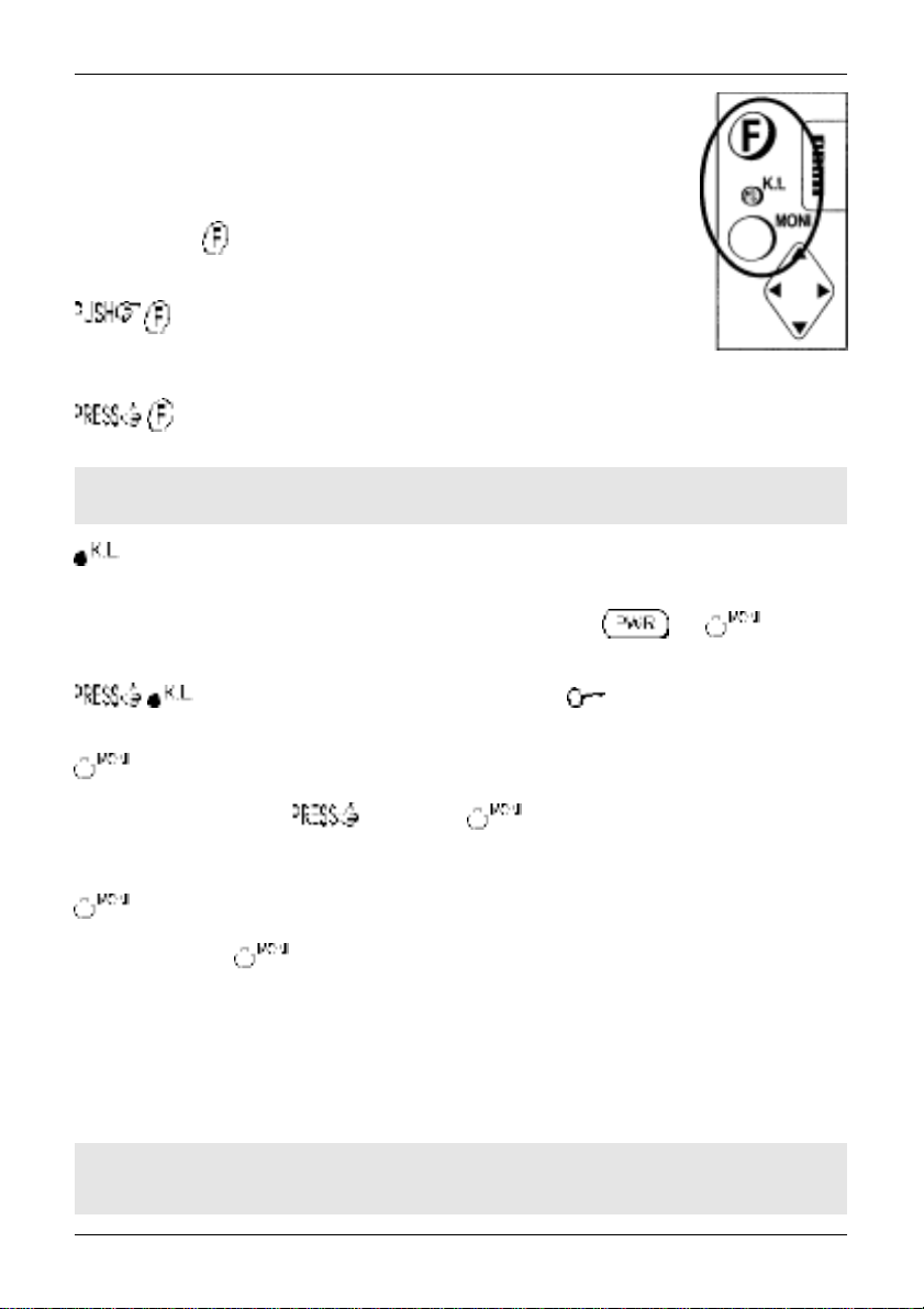
1-5-3 Side panel
The left hand side of the AR8200 comprises of three push keys, a nest of four
arrow keys and a rotary main dial. An eject slider is also provided to release the
optional SLOT CARD.
FUNCTION KEY
The function (shift) key is used to select the second function of keypad facilities.
to toggle the function status on/off. A solid reverse legend LCD
“FUNC” indicates when function shift is in operation. The function status is
terminated automatically in the normal course of entry.
Section 1-5-3
to initiate
“FUNC” legend flashes when
double-shift
double-shift
which is used in certain menus as a short-cut. The reverse
is engaged.
&Note: When the “FUNC” legend is displayed in VFO mode, the tuning speed will be
increased to assist rapid frequency change using the arrow keys and main dial.
The KEY LOCK is intentionally small to reduce the chances of accidental operation. Key lock is useful
when you do not wish an important frequency to be lost or the AR8200 to be incorrectly set to a different
frequency. The key lock status is
not affected by key lock.
to toggle the key lock on /off, an LCD key symbol “ ” indicates status.
The MONITOR key is used to force the squelch open so that you may manually intervene to ensure that
no weak signals are missed. and hold the key to defeat the squelch control (saves
turning the squelch control fully anti-clockwise then back to threshold position).
When the “DUP” legend is displayed during frequency offset or VFO SCAN (DUPLEX) operation, the
key forces the AR8200 to switch to the alternative frequency.
In SCOPE mode, the key enables the reception of the marker frequency.
MAIN DIAL
This recessed rotary control is intended to be scrolled up and down using the thumb of your left hand
(although you may adjust it using the middle finger of your right hand etc). Primarily this is the tuning
control, upward rotation tunes the AR8200 upward in frequency and downward rotation tunes downward
in frequency using the selected tuning step size. When the “FUNC” legend is displayed, the tuning
speed will be increased. The main dial is also used to move between menus and manipulate input
through menus (generally mimicking the arrow keys).
not
deactivated by switch off / on, the and keys are
&Note: The main dial also has a switch capability, this is why the main dial has lateral
movement. However, this switch capability is not used by the AR8200.
15
 Loading...