


Contents
(1) Table of contents .......................................................................... |
1 |
|
(2) Introduction ................................................................................... |
2 |
|
2-1 |
Key information and common menus .................................. |
3 |
2-2 |
Accessories supplied .......................................................... |
4 |
(3) Major Features .............................................................................. |
4 |
|
(4) Precautions ................................................................................... |
4 |
|
4-1 |
Location .............................................................................. |
4 |
4-2 |
Looking after your receiver ................................................... |
5 |
4-3 |
Power requirements ............................................................ |
5 |
4-4 |
Aerial (antenna) connection ................................................. |
5 |
(5) Controls and functions ................................................................ |
6 |
|
Front panel |
|
|
5-1 |
On/Off power switch ............................................................ |
6 |
5-2 |
S-meter (signal strength meter) ........................................... |
6 |
5-3 |
Liquid Crystal Display (LCD) ................................................ |
6 |
5-4 Main (large) rotary tuning control - MAIN DIAL .......................... |
8 |
|
5-5 Sub (small) rotary tuning control - SUB DIAL ............................ |
8 |
|
5-6 |
Torque adjustment (MAIN DIAL brake) ..................................... |
8 |
5-7 |
Removable feet ................................................................... |
9 |
5-8 |
Internal speaker .................................................................. |
9 |
5-9 |
SQ - squelch control (plus RF control) ................................. |
9 |
5-10 |
Volume control (AF GAIN) ................................................. |
10 |
5-11 |
ACC 1 accessory number one socket ................................ |
10 |
5-12 |
Headphone socket ............................................................. |
10 |
5-13 |
Front panel keys ................................................................ |
10 |
Rear panel |
|
|
5-14 |
DC 12V - external power connection .................................. |
15 |
5-15 |
ACC 2 (accessory 2 socket) ............................................. |
15 |
5-16 |
EXT SP - external speaker output socket ........................... |
16 |
5-17 |
REMOTE - RS232C computer control port ........................ |
16 |
5-18 |
I.F. OUTPUT (10.7 MHz) ................................................... |
16 |
5-19 |
STD IN (10 MHz) ............................................................... |
16 |
5-20 |
MUTE ............................................................................... |
16 |
5-21 |
ANT 2 ............................................................................... |
17 |
5-22 |
ANT 1 ............................................................................... |
17 |
(6) Basic manual operation of the receiver ..................................... |
17 |
|
6-1 |
Switching on for the first time .............................................. |
17 |
6-2 |
Changing VFO .................................................................... |
17 |
6-3 |
Tuning the receiver using the rotary controls ........................ |
18 |
6-4 |
Entering a frequency via the numeric keypad ....................... |
18 |
6-5 |
Correction of frequency input via the numeric keypad ........... |
19 |
6-6 |
Selecting tuning step (increment) ......................................... |
19 |
6-7 Step-adjust .......................................................................... |
20 |
|
6-8 |
FREQUENCY OFFSET ....................................................... |
22 |
6-9 |
Changing receive mode (AUTOMODE) ................................ |
22 |
6-10 |
IF BANDWIDTH ................................................................ |
24 |
6-11 |
AF SET - (Audio characteristics) ........................................ |
25 |
6-12 |
Audio tone eliminator (T-ELMT) ......................................... |
27 |
6-13 |
DTMF decoder .................................................................. |
28 |
6-14 |
RF Attenuator & preamplifier ............................................. |
28 |
6-15 |
CONFIG menu outline of facilities ...................................... |
28 |
6-16 CONFIG - LAMP ............................................................... |
29 |
|
6-17 |
CONFIG menu - BEEP ..................................................... |
29 |
6-18 |
|
CONFIG - EXTERNAL I.F. output (SDU5000) ..................... |
29 |
6-19 |
|
CONFIG - Computer control BPS ....................................... |
29 |
6-20 |
|
CONFIG - Advanced aerial switching .................................. |
30 |
6-21 |
|
CONFIG - Frequency standard ............................................ |
32 |
(7) Memory banks & channels ............................................................ |
33 |
||
7-1 |
Storing receive data into memory - VFO mode ...................... |
33 |
|
7-2 |
Memory recall - Recalling receive data from memory ............. |
34 |
|
7-3 |
Transfer of memory channel to VFO ...................................... |
35 |
|
7-4 |
Changing and deleting memory data ..................................... |
35 |
|
7-5 |
Deleting memory channels and banks ................................... |
36 |
|
(8) SCAN - scanning memory channels & banks ............................. |
37 |
||
8-1 |
SCAN - outline introduction to facilities available ................... |
37 |
|
8-2 |
Starting to SCAN, considerations .......................................... |
37 |
|
8-3 |
SCANNING a memory bank ................................................. |
38 |
|
8-4 |
Selecting a single memory bank to scan ................................ |
38 |
|
8-5 |
Memory bank linking to scan ALL memory banks .................. |
39 |
|
8-6 |
Specifying memory bank linking ............................................ |
39 |
|
8-7 |
Scanning a memory bank which is not linked ........................ |
39 |
|
8-8 |
SCAN channel PASS (lockout) .............................................. |
40 |
|
8-9 |
Cyber Scan in SCAN mode .................................................. |
41 |
|
(9) Additional SCAN facilities ............................................................. |
41 |
||
9-1 SCAN - PAUSE .................................................................... |
41 |
||
9-2 SCAN - DELAY .................................................................... |
42 |
||
9-3 |
SCAN - LEVEL SQUELCH ................................................... |
42 |
|
9-4 SCAN - VOICE ..................................................................... |
42 |
||
9-5 |
SCAN - MODE (receive mode AM, FM etc) ........................... |
43 |
|
(10) SELECT SCAN - special select scan list overview ................... |
43 |
||
10-1 |
|
Tagging scan select channels .............................................. |
43 |
10-2 |
|
SELECT SCAN - while in SCAN MODE .............................. |
44 |
10-3 |
|
SELECT SCAN while in MEMORY RECALL mode ............. |
44 |
10-4 |
|
Starting SELECT SCAN ..................................................... |
44 |
10-5 |
|
Deleting all SELECT SCAN channels in one go ................... |
44 |
(11) Priority operation .......................................................................... |
45 |
||
11-1 |
|
Engaging PRIORITY channel .............................................. |
45 |
11-2 |
|
Changing PRIORITY channel parameters ............................ |
45 |
(12) SEARCH ......................................................................................... |
46 |
||
12-1 |
|
Manual SEARCH between two VFO frequencies (VA, VB) |
... 46 |
12-2 |
|
Simple search (VC, VD, VE) ............................................... |
47 |
12-3 |
|
Optimising VFO search parameters ..................................... |
48 |
12-4 |
|
Program search banks ........................................................ |
49 |
12-5 |
|
Starting program search ...................................................... |
50 |
12-6 |
|
Cancelling, restarting program search ................................. |
50 |
12-7 |
|
Programming and reprogramming SEARCH BANKS .......... |
51 |
12-8 |
|
Deleting PROGRAM SEARCH BANKS ............................... |
53 |
12-9 |
|
SEARCH - outline introduction to additional facilities ........... |
53 |
12-10 |
Linking program search banks ........................................... |
54 |
|
12-11 |
Linking only a few search banks ......................................... |
55 |
|
12-12 |
Searching a bank which is not selected in BANK LINK ...... |
55 |
|
12-13 |
Additional PROGRAM SEARCH facilities (introduction) |
..... 55 |
|
12-14 |
PROGRAM SEARCH - PAUSE ......................................... |
55 |
|
12-15 |
PROGRAM SEARCH - DELAY ......................................... |
56 |
|
12-16 |
PROGRAM SEARCH - LEVEL SQUELCH ....................... |
56 |
|
12-17 |
PROGRAM SEARCH - VOICE ......................................... |
57 |
|
12-18 |
Cyber Search ................................................................... |
57 |
|
12-19 |
AUTO-STORE .................................................................. |
58 |
|
AR5000 OPERATING MANUAL |
PAGE 1 |
(13) |
Frequency Pass .......................................................................... |
58 |
|
13-1 |
Register PASS Frequency ................................................ |
59 |
|
13-2 |
|
Manually adding a PASS frequency ................................... |
59 |
13-3 |
Editing pass frequencies ................................................... |
60 |
|
13-4 |
|
Deleting individual pass frequencies .................................. |
60 |
13-5 |
|
Deleting complete banks of pass frequencies ..................... |
61 |
(14) |
Real time clock ........................................................................... |
61 |
|
14-1 |
Displaying the clock .......................................................... |
61 |
|
14-2 |
Setting time ...................................................................... |
62 |
|
14-3 |
Alarm clock ...................................................................... |
63 |
|
14-4 |
ALARM programming ....................................................... |
63 |
|
14-5 |
ALARM activation ............................................................. |
64 |
|
14-6 |
SLEEP timer .................................................................... |
64 |
|
(15) |
Option - Descrambler (voice inverter) - DS8000 .................... |
65 |
|
15-1 |
Descrambler installation .................................................... |
65 |
|
15-2 |
Descrambler operation ...................................................... |
66 |
|
(16) |
Option - CTCSS tone squelch - CT5000 .................................. |
66 |
|
16-1 |
|
Installation of the CT5000 ................................................. |
67 |
16-2 |
|
Operation of the CT5000 - overview .................................. |
67 |
16-3 |
CTCSS SEARCH ............................................................. |
67 |
|
16-4 |
CTCSS SQUELCH ........................................................... |
68 |
|
(17) |
Optional I.F. filters (500 Hz, 2.5 kHz & 5.5 kHz) ...................... |
68 |
|
17-1 |
|
Fitting the optional 500 Hz filter ......................................... |
68 |
17-2 |
|
Installation of other filters .................................................. |
69 |
(18) |
Trouble shooting - microprocessor reset ............................... |
70 |
|
18-1 |
Power Off / On .................................................................. |
70 |
|
18-2 |
CPU reset switch .............................................................. |
70 |
|
18-3 |
CPU soft reset .................................................................. |
70 |
|
18-4 |
AF.SET INT/EXT .............................................................. |
71 |
|
18-5 |
|
What next - dealer support ................................................ |
71 |
18-6 |
|
Power-up special key sequences ....................................... |
71 |
(19) |
Optional accessories ................................................................. |
72 |
|
(20) |
Aerials (Antennas) and earth systems .................................... |
72 |
|
(21) |
Propagation - short wave bands .............................................. |
75 |
|
(22) |
Specification ............................................................................... |
76 |
|
(2) Introduction
Thank you for purchasing the AOR AR5000 wide band all mode receiver. The AR5000 uses the very latest NCO (Numerically Controlled Oscillator) technology to ensure the highest levels of design, performance and reliability.
It is recommended that you carefully read this handbook and familiarise yourself with the receiver before placing it into operation. Every effort has been made to make this manual correct and up to date. Due to continuous development of the receiver and by error or omissions anomalies may be found and this is acknowledged. Most apparent faults are usually due to accidental misoperation of the receiver, carefully read all of the manual before deciding to return the receiver for repair.
Although carefully designed, this receiver (like all receivers) suffers from a degree of internal noises known as spurii. They are a product of the receiver’s circuitry and do not represent a fault.
© This manual is protected by copyright AOR Ltd 1995, 1996. No information contained in this manual may be copied or transferred by any means without the prior written consent of AOR Ltd. ® AOR and theAOR logo are registered trade marks of AOR, Ltd. All other trade marks and names acknowledged. E&OE.
If you are very familiar with operating similar equipment you may choose to refer directly to section
(6) once you are sure the precautions are fully understood.
Operating manual Conventions
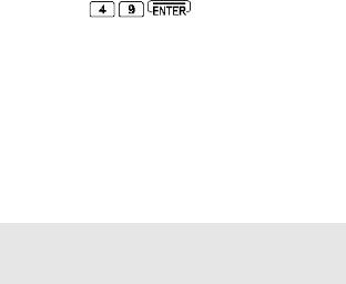
Where text appears in a graphic format such as  , the key is to be pressed exactly as shown.
For example:
Means press the 4 key followed by the 9 key followed by the enter key.
Words contained in speech marks “PASS” or “F-PASS VFO” refer to indications displayed on the Liquid Crystal Display.
Where the mode of FM is referred to, this indicates Frequency Modulation (narrow and wide depending upon I.F. filter selection). For clarity, the triple function [MHz] [ENT] [TEXT] key is referred to as  .
.
Note: If you take too long entering data (about 90 seconds) the display will revert to it’s original condition.
PAGE 2 AR5000 OPERATING MANUAL
2-1 Key information and common menus
The five VFOs are assigned special status (6-2):
VFO-A (VA) |
Manual search between VFO-A |
|
and VFO-B |
VFO-B (VB) |
Manual search between VFO-A |
|
and VFO-B |
VFO-C (VC) |
Simple search |
VFO-D (VD) |
Simple search & accept |
|
frequency from the search mode |
VFO-E (VE) |
Simple search & accept |
|
frequency from the scan mode |
Memory write (7-1):
Press and hold the  key for more than one second and follow the prompts.
Mode selection (6-9):
To change the receive mode, briefly press the  key. The “MODE” legend will flash on the LCD to confirm that the mode select menu has been activated.
The following modes are available from the MODE menu: “AUTO”, “ FM”, “ AM”, “ LSB”, “ USB” and
“CW”. If automode is currently in use, the legend
“AUTO” will be displayed on the LCD. When you have made selection, press  to accept the new mode.
To select automode press and hold the  key for more than one second, the legend “AUTO” is displayed on the LCD to confirm operation.
AGC (6-9):
Press 

When in automode the legend “AUT” is displayed.
AGC OFF
AGC FAST
AGC MIDDLE
AGC SLOW
Audio characteristics (6-11):
Press 

A-LPF 3.0 kHz
A-HPF 0.05 kHz
DE.EMP 750
CW.PITCH 0.7 kHz
AUDIO INT
Option menu (6-12, 6-13, 15-2, 16-2):
Press 

DE-SCR OFF (if DS8000 option is fitted) CTCSS OFF (if CT5000 option is fitted)
DTMF OFF
T-ELMT OFF
Config menu (6-16, 6-17, 6-18, 6-19, 6-20, 6-21):
Press 

LAMP ON
BEEP 4
EXT-IF OFF
BPS 9600
ANT 1
STD.INT 12.8 MHz
Delete menu (7-5, 10-5, 8-8, 12-8, 13-5):
Press  then press and hold the
  key for more than one second.
DEL MEM-CH
DEL SEL-CH
DEL M-PASS
DEL SRCH
DEL F-PASS
Additional scan facilities (9-1, 9-2, 9-3, 9-4, 9-5):
Press 


PAUSE OFF
DELAY 2.0
L-SQ OFF
VOICE OFF
MODE ALL
Additional VFO facilities (12-3):
Press 

DELAY 2.0
L-SQ OFF
VOICE OFF
Programming search banks (12-7):
Press 

LO
HI
MODE FM (set to AUTO if AUTOMODE is used) IFBW 0.5 (skipped if AUTOMODE is used)
STEP 1.000 (skipped if AUTOMODE is used)
TXT
Additional search facilities (12-14, 12-15, 12-16, 12-17, 12-19):
Press 


PAUSE OFF
DELAY 2.0
L-SQ OFF
VOICE OFF
A.STORE OFF
AR5000 OPERATING MANUAL |
PAGE 3 |
Clock programming (14-2):
Press  then press and hold the
  key for more than one second.
SELECT 24H / SELECT 12H 6-25-00 1 / AM.6-25-00 1 TXT 1
4-23-30 2 / PM.4-23-30 2 TXT 2
Alarm clock programming (14-4):
Press  then press and hold the
  key for more than one second.
ALARM 0-00
ALARM LENGTH 15
ALARM ALM RADIO / ALARM ALM BEEP ALARM VOLUME 80
2-2 Accessories supplied
a.c. mains power supply
Operating manual
Additional extensions for front feet
(3) Major Features
l Large LCD
A large rear illuminated liquid crystal display (LCD) provides display of receive frequency, mode, etc plus alpha numeric text along with each search bank and memory channel.
l Massive memory
A large EEPROM memory store holds a total of 1000 memory channels (100 ch x 10 banks), and 20 search banks. Each search bank has a total of 100 PASS frequencies plus a further 100 for VFO operation. This type of memory store does not require external power or internal battery power to retain the memory contents. The real time clock is backed by an additional super capacitor which will maintain the correct time for approximately 50 hours even with no external power connected to the receiver.
l Wide frequency coverage, all mode, automode
The AR5000 has a very wide frequency coverage of 10kHz to 2600MHz (acceptable input from 5 kHz) in FM, AM, USB, LSB & CW. The all new receive circuitry provides high sensitivity and superior strong signal handling thanks to the clever RF design which is optimised to each receiving band with electronic tuning (pre-selector) circuits up to 1GHz.
Comprehensive bandplan information specific to the target market area has been programmed into the AR5000
receiver. This inclusion will greatly simplify both frequency entry and search programming.
The receiver will automatically select the appropriate mode and channel step. Of course, should you wish then both the mode and channel step may be manually changed as desired.
l Wide variety of useful operational features
wHigh speed Cyber Scan and Cyber Search
wMulti VFO (5-VFO)
wA minimum of 1 Hz tuning rate by NCO
wFrequency Offset facility to help follow duplex transmission
wRF preamp & attenuator
wAuto aerial selection - programmable
wWide range of search/scan facilities
wPre-programmed automode (receive mode, step size, IF bandwidth)
wStep-adjust for unusual banplans
wStandard TCXO plus external 10 MHz input
wTwin tuning knob (MAIN DIAL has a variable torque controller)
l Other useful features
wVariable beep tone
wSleep timer On/Off, alarm
wAnalogue signal meter for easy reading
wOutput terminals for external decoder, etc
wAuto-memory facility (On/Off switchable)
wRS232 PC remote control
wLarge capacity EEPROM for memory backup
wTuning step size from 1Hz to 999.999kHz
(4)Precautions
4-1 Location
Do not use or leave the receiver in direct sunlight (especially the LCD). It is best to avoid locations where excessive heat, humidity, dust and vibration are expected. Always treat the receiver with care.
Take care to avoid spillage or leakage of liquids into the receiver and a.c. power supply. Special care should be taken to avoid liquid entering via the power jack and earphone sockets.
Avoid static discharge from discones or long wire aerials, earth to a central heating radiator or similar earthing point in order to discharge the wire before connection to the receiver. Always disconnect and earth any external aerial system if an electrical storm is expected.
Avoid a rapid power switch On/Off sequence. If switched off, leave at least two seconds before switching on again. Ensure the a.c. mains plug connections are tight and other d.c. connections (such as cigar lighter plugs) are secure.
Avoid strong RF fields from nearby transmitters. If in doubt, disconnect the AR5000 from the aerial and switch the set off.
PAGE 4 AR5000 OPERATING MANUAL

4-2 Looking after your receiver
Always keep the receiver free from dust and water. Use a soft dry cloth to gently wipe the set clean. Never use chemicals such as benzine or thinners which will damage certain parts.
4-3 Power requirements
The AR5000 is designed for operation from an external d.c. supply of 12 ~ 16V at approximately 1.0A minimum.
Always use the mains power supply provided, or a regulated d.c. power supply of 13.5V @ 1.0A or more using the optional DC3000 connecting lead. Always switch the receiver off when connecting or disconnecting the power lead.
Note: The d.c. input socket uses a special type of connector. This plug / socket is of a moulded type and pre-wired, positive is the RED wire. The chassis of the receiver is negative ground.
The power supply is pre-fitted with the correct mains (a.c.) plug for the appropriate market. This AR5000 power supply has no connection to the EARTH pin of the mains plug. A separate earth may be taken to the outer connection of the SO239, N-type of BNC rear panel sockets, then to a water pipe, central heating system radiator or external earth rod. If fitting a separate external earth rod, consider the implications carefully if your a.c. mains supply uses a Protective Multiple Earth (PME) system. If in doubt consult an expert electrician. Never earth to a gas pipe!
Safety notice: Allow air to circulate around the power supply, never cover the top with paper, clothing etc. Always disconnect the power supply from the a.c. mains supply when not in use.
The aerials input selection may be programmed by the user for different bands, at default these are:
ANT 1: 50 OHM N-type socket - All frequencies
ANT 2: 50 OHM SO239 socket - User selectable
Aerial inter-series adapters are readily available to convert from N-type, SO239 etc to BNC or other plugs & sockets as required allowing straight forward connection to almost any aerial.
An aerial attenuator system allows selection of AUTO, 0dB, 10dB or 20dB. The attenuator control switches in / out of circuit the RF preamplifier and attenuator affecting the sensitivity of the receiver. 20dB may not be selected above 230 MHz. RF gain is also available in all modes via a front panel rotary control, this is especially useful in providing optimum audio quality for SSB operation.
Aerial Tuning Units (ATU)
An ATU can improve the selectivity of any receiver when listening to the short wave bands when connected to long wire aerials (other than a short wire of a few metres). This valuable extra selectivity is created provided by rejecting out of band signals enabling the receiver to single out one band of frequencies while rejecting potentially strong unwanted transmissions. The AR5000 has a built in automatic preselected front end for frequencies up to 1GHz.
An ATU is usually constructed in a small box with about two or three controls on the front panel. One disadvantage however is the need to constantly retune the ATU when changing frequency. An ATU of this type has no active circuitry so is known as a passive device.
Active short wave desktop loop aerials
Designed for the short wave bands (such as the AOR LA320), loop aerials have the advantage of small size when compared to long wire aerials, and being within easy reach of the operator it can be rotated to provide directivity. The circuitry offers a small level of gain with the advantage of selectivity similar to that of an ATU.
* For further information please refer to section 20 of this manual regarding aerial and earth systems.
4-4 Aerial (antenna) connection
The AR5000 has two 50 OHM aerial input sockets fitted as standard to the rear panel. Further aerials may be connected using the optional aerial switching unit AS5000 with switching data being fed from a rear panel accessory socket (ACC 2).
AR5000 OPERATING MANUAL |
PAGE 5 |

(5) Controls and functions
The AR5000 receiver is housed in a strong metal cabinet. Controls for operation are located on the front of the cabinet with connections to the rear.
Front panel
5-1 On/Off power switch 
This rectangular shaped plastic button (key) is located in the top left corner of the front panel and switches the set On/Off.
To switch the set on, connect a suitable power source and depress the  switch, the microprocessor will then power the set up.
To switch the receiver off press the  switch a second time, the microprocessor will then switch the set off.
5-2 S-meter (signal strength meter)
The rear illuminated analogue SIGNAL METER is located to the left hand side of the front panel. Relative strength of incoming signal is indicated in standard S points where S1 is weak and S9 is strong. Calibration above S9 is in dB up to +60dB. As with other receivers, the meter is for relative signal strength comparison and calibration may not be totally reliable especially on FM mode.
5-3 Liquid Crystal Display (LCD)
Display of operational information is provided via a high contrast wide angle backlit green LCD, this includes frequency, mode, bandwidth, alpha-numeric comments for memory channels and search banks etc.
LCD test
The LCD may be tested by holding the |
key while |
switching on the receiver using the |
key. |
1 Ensure that set is switched off. Press and hold the  key... don’t let go of it!
2Press the  key to switch on the AR5000, this may be a two handed operation.
3Release the  key. All LCD characters will be displayed.
4Press the  key to restore a normal display.
PAGE 6 AR5000 OPERATING MANUAL
The display is split into 28 specific areas, a summary of which follows:
1“BUSY” legend appears when the squelch is open (signal present).
2“FUNC” as a reverse legend appears when the  key is pressed signifying that the receiver’s microprocessor is awaiting the press of another key, where the SECOND FUNCTION shown in white (not orange) adjacent to the
keys will be activated... an example is 
 to activate the keylock. When the second function is activated, the “FUNC” legend disappears and often a new LCD legend appears to confirm selection.
3“ANT” aerial (ANTENNA) number currently in use. As standard this will be “ANT 1” or “ ANT 2” but may be higher if the optional aerial switch AS5000 is in use.
4“RMT” signifies whether the receiver is under normal keypad control or by a REMOTE device such as the optional SDU5000 spectrum display unit or computer. RMT = ReMoTe, no legend indicates standard keypad operation.
5“KEY” indicates that KEY LOCK has been selected, this is activated by the key sequence 
 . Key lock prevents accidental changing of the receiver’s front panel controls. When in the locked condition only the
Volume, Squelch, Power and  controls will respond.
6 “ALARM” indicates that the alarm facility has been activated. The legend “ALARM” will be displayed on the LCD even when the AR5000 is switched off (as long as power is maintained to the receiver). At the prescribed time, the receiver will automatically switch on. It is possible to program the switch on time, select radio or beep, volume level and duration before switch off.
To activate the alarm use the sequence 
 , the same sequence cancels the alarm as a toggle. This is very useful for setting up unattended recording or when using the AR5000 as an alarm clock!
7 “SLEEP” indicates that the sleep timer circuit has been activated. When the prescribed time for sleep has elapsed the receiver will switch off automatically... very useful when listening to the radio in bed.
To program the sleep time press  then press and
hold  for more than one second. A sleep selection menu will be displayed, use the MAIN DIAL or SUB DIAL to
select the required time (between 1 & 120 minutes) then press 
To activate / deactivate the SLEEP facility use the toggle sequence 

8“PRIO” indicates when the PRIORITY facility has been activated by pressing the  key.
key.
9“N-SQL” and “ L-SQL” indicate that the receiver is set
to operate from its squelch circuit, the “BUSY” legend appearing during activity. In normal use “N-SQL” noise squelch is used but “L-SQL” (level squelch) may be selected for search and scan operations. If neither legend is displayed, the RF GAIN facility has been activated.
10“TONE” is displayed when the optional CTCSS board has been selected for tone decoding, often used by amateur radio repeaters and utility users.
11“FM”, “ AM”, “LSB”, “USB” or “CW” - indicates AR5000 receive mode.
12“SCAN” is displayed when the memory banks are SCANNED (automatically checked for activity).
13“PAUSE” is a selectable parameter for SCAN and SEARCH modes, the legend indicates that the facility is in operation. The AR5000 will wait the specified duration of pause time on a busy frequency before moving off again even if the frequency is still busy.
14“VCS” is a selectable parameter (VOICE) for SCAN and SEARCH modes, the legend indicates that the facility is in operation. The AR5000 may be programmed to ignore certain types of blank carriers and unwanted signals. The value may be selected between 1 to 255 and OFF while in the scan and search parameter program sub menus.
15“L-BANK” as opposed to “ BANK” indicates that more than one scan or search bank has been selected to be scanned or searched as a group. In other works the banks have been LINKED, bank link.
16“BANK” indicates that the receiver is currently in memory recall mode (no SCAN legend), scan mode (two lines of bank & channel numbers) or search mode.
AR5000 OPERATING MANUAL |
PAGE 7 |

In search mode only a bank number and the legend “SR” is displayed - but no channel number.
17The one or two digit number indicates which scan or search banks have been selected. In scan mode the range is 0 to 9 (ten banks) and in search mode 00 to 19 (twenty banks).
18Attenuator setting. The display is always proceeded
by “ATT” (for attenuator) and followed with dB for level (decibel). “ATT 00 dB” indicates attenuator OFF, “ATT
10dB” indicates that 10dB of attenuation has been applied and “ATT 20 dB” indicates that 20dB of attenuation has been applied. The attenuator menu is
activated by the  key.
key.
Note: Above 230 MHz only 0dB & 10dB are available and the RF preamplifier is always in circuit (“AMP” legend displayed). Below 230 MHz the “AMP” is displayed in the “00” position.
19 Frequency, text and various status messages are displayed in this area. There are a maximum of ten digits providing frequency read-out down to 1Hz resolution. In text mode a maximum of eight characters may be displayed for search bank and memory channel recognition. The frequency red-out is always followed by the legends kHz or MHz.
Note: frequencies below 3.0 MHz (3000 kHz) are always shown as kHz.
20 “AMP” is displayed when the RF preamplifier is switched on. The amplifier is selected in the ATTENUATOR sub menu accessed by pressing 
Note: Above 230 MHz the RF preamplifier “AMP” legend is always displayed. Below 230 MHz the “AMP” is displayed in the “00” attenuator position.
21“STEP” is displayed during entry of STEP SIZE (tuning increment) for manual tuning or search operations. “STEP-ADJ” is displayed when the STEP-ADJUST facility is in use so that unusual bandplans may be correctly tracked.
22“AUTO” is displayed when the receive mode selection is set to AUTO. In this condition the AR5000 will select the appropriate receive mode, channel step (and many other parameters) for the frequency entered in VFO mode and during search programming. This simplifies operation and speeds up manual changes in frequency.
23“FR-OFS” is displayed when the FREQUENCY OFFSET facility is selected. This enables a fixed offset frequency to be stored in a special bank allowing quick frequency change and monitoring of duplex pairs such as inputs to amateur band repeaters or VHF marine traffic.
24“=” AGC OFF indication. When the AGC (Automatic Gain Control) is switched off, strong signals may sound distorted... however AGC off may be useful for DX’ing when the optional 500 Hz Collins mechanical CW filter is fitted. To ensure that the AGC is not switched off unintentionally, two parallel bars are displayed between
the MHz / kHz LCD legends. The available selection of AGC is: OFF, FAST, MIDDLE & SLOW.
25 I.F. filter bandwidth is displayed on the LCD in kHz. The options are:
“220”, “110”, “30”, “ 15”, “ 6”, “ 3”, (“ 0.5” optional), i.e. “3K” for 3.0 kHz.
26“PASS” is displayed to indicate that a memory channel has been LOCKED OUT so that it will not be scanned, similarly with a frequency in search mode, it will be skipped.
27“AS-M” indicates that active frequencies found while
in search mode will be automatically added to memory bank “0” (Auto Store to Memory). Auto-store is switched on.
28The two digit number ranging from 00 to 99 indicates that the AR5000 is in MEMORY RECALL or SCAN mode (if the scan legend is also displayed). The two digit number
represents the memory channel number. The 
 keys or SUB DIAL select bank, the MAIN DIAL selects
memory channel number and the keypad allows direct access to the three digit bank/channel number i.e. 

 for bank 1 channel 23, there is no need to press enter.
In SEARCH mode the letters “SR” are displayed in this lower right corner of the LCD with the bank number displayed above.
5-4 Main rotary tuning control - MAIN DIAL
The large rotary tuning control is prominently located on the front of the cabinet. This control changes the received frequency up and down in whatever step increment has been selected between 1 Hz ~ 999.999 kHz. This control is often referred to as the VFO (Variable Frequency
Oscillator), a rather historic name for a tuning mechanism. In this operating manual it is referred to as the MAIN DIAL.
5-5 Sub rotary tuning control - SUB DIAL
This smaller control may be programmed in a number of different ways. It too is largely used to tune the receiver and is intended to make channel tuning easier where channelised bandplans are in force (such as 2m amateur band FM allocations etc). The control is extensively used during the input and changing of operational parameters
such as attenuator, IFBW etc. In this operating manual the control is referred to as the SUB DIAL.
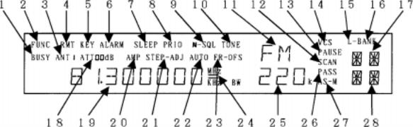
5-6 Torque adjustment (MAIN DIAL brake)
This small slide control affects the free movement of the large rotary tuning control (MAIN DIAL), this is useful to help
prevent unintentional frequency change due to accidental movement of the MAIN DIAL. When the lever is in the
UPWARD position, the MAIN DIAL is FREE RUNNING, moving the lever downward adds friction to dampen the control.
PAGE 8 AR5000 OPERATING MANUAL
Note: A microprocessor reset switch is hidden behind the upper section of the lever’s slot. Reset can be useful if the receivers operation has been upset due to static discharge or power supply transients. Details are given in section 18 of this operating manual.
5-7 Removable feet
The front of the receiver is lifted up clear of the table top to allow easy access to the front panel controls and clear visibility of the LCD. The front feet may however be removed (unscrewing by hand in an anti-clockwise direction using the knurled disk) for mobile operation. Additional height may be added by fitting the two spacers provided with the receiver in the accessories bag.
clockwise until the background noise just disappears (threshold), this is the most sensitive setting of the control. In practice the control is usually rotated a little further clockwise beyond the threshold point to prevent the receiver from stopping on noise or very weak and unreadable signals.
If the control is rotated too far clockwise then weaker signals will be totally lost and only local strong signals will be heard.
When the squelch control is rotated anticlockwise so that background noise is audible, the squelch is referred to as being OPEN. In a similar manner, when the squelch control is rotated clockwise so that the background noise is muted, the squelch is referred to as being CLOSED.
The squelch is not normally used when listening to short wave transmissions due to the relatively high short wave background noise, the usual setting for the control when listening to short wave is fully anticlockwise (squelch open).
When the squelch is OPEN (busy), a “BUSY” legend is displayed on the left of the LCD.
Note: Even when the squelch is fully CLOSED a very low level background noise may still be audible. This is because the receiver’s audio amplifier circuit is permanently operational in order to provide fast search / scan rates and an efficient squelch opening characteristic. This phenomenon is common with other wide band receivers on the market today.
When the squelch is set up for normal operation, the legend “N-SQL” is displayed on the top line of the LCD slightly centre-right, this stands for Noise SQueLch.
5-8 Internal speaker
The AR5000 is fitted with a lower case mounted speaker. In order to provide best projection of audio from the receiver, a custom horn has been designed and fitted to the receivers underside (visible from the front panel).
5-9 SQ - squelch control (plus RF control)
The squelch control is used to eliminate unwanted background noise when monitoring a normally inactive frequency and is also used by the AR5000 microprocessor to determine when a channel is active (busy). The receiver cannot scan or search when the background noise is present.
The squelch control requires careful setting to achieve optimum operating performance. Rotate the control
RF GAIN
It is possible to configure the squelch control to function as RF GAIN by selecting 
 on the keypad, the “N-SQL” legend is removed from the LCD to confirm operation. The RF GAIN control reduces the level of amplification applied to the receiver’s I.F. circuits. This has the effect of reducing the sensitivity of the receiver in much the same way as the attenuator but is more controllable.
The usual position for the AR5000 RF GAIN control is fully anti-clockwise when the set is at its most sensitive. As the control is rotated clockwise the S-meter will advance to indicate what strength signal is required to produce solid and readable results.
The control is most useful on SSB where the RF GAIN should be adjusted so that the peaks of SSB signals just deflect the S-meter. This will greatly reduce the level of background noise especially during pauses in speech or inactivity.
When RF GAIN is used (squelch switched off), the word “N-SQL” is removed from the top line of the LCD.
AR5000 OPERATING MANUAL |
PAGE 9 |
5-10 Volume control (AF GAIN)
The volume control is located to the left of the front panel underneath the signal meter. It is used to set the required audio output through the loudspeaker or headphone. When turned fully clockwise the volume is at maximum, when rotated fully anti-clockwise the volume is reduced to minimum.
5-11 ACC 1 accessory number one socket
A front panel accessory socket is located to the lower left corner of the front panel which provides outputs for audio, tape motor switching and discriminator.
4 & 5 Tape record motor switching using a non-polarised photo-MOS relay. The switched output is designed for low voltage (12V) d.c. with a maximum current of 350mA, the insulating voltage is 40V. The switch-on-impedance is 1.2 OHMS.
6High level audio output. The AR5000 provides both high and low level audio output for feeding tape recorders and other remote devices, the output is independent of volume control level. Pin 6 provides a level of 700mV RMS @ 600 OHMS, ideal for line output.
7Low level audio output. Pin 7 provides a level of 2mV RMS @ 600 OHMS, ideal for microphone input of tape recorders.
8Ground.
A standard 8-pin mini-din connector is used (which is widely available or the optional CR5000 tape lead may be used). The pin-outs for ACC 1 are as follows:
112V d.c. output with a maximum available current of 30mA (useful for feeding electret microphones and other low power devices). The voltage will fluctuate depending upon supply voltage being fed to the AR5000.
2Detector output (without audio filtering), useful for improving performance of certain decoders such as pagers etc. The level output is 180mV RMS and impedance is 100k OHMS or greater.
3Audio input. The receiver’s audio amplifier stage can be configured to use signal from an external device rather than from its own receive circuits. This permits break-out of signal for processing (DSP etc) which is then reapplied to the receiver for amplification. The input circuit is configured for a level of 180mV at a nominal impedance of 100k OHMS.
As the internal audio path needs to be cut as part of the break-out set-up, the microprocessor has to be configured accordingly. To select EXTERNAL AUDIO
INPUT press 
 then press the
  key four times to display “AUDIO INT”. Rotate the SUB DIAL
to display “AUDIO EXT” then press  . The usual sound from the receiver will be muted until an external audio signal is applied (fed back in).
Of course, the set’s own audio may be fed out through the ACC 1 socket and back in again which increases the receivers flexibility under certain professional monitoring applications.
Note: At high volume levels, a low level leakage of internal audio signal may still be heard from the receiver’s speaker... this is normal and does not represent a fault (or problem).
5-12 Headphone socket
This quarter inch (6.3mm) socket is located on the left hand side of the front cabinet directly underneath the power and  keys. A pair of headphones or earphone may be connected with an impedance of 8 OHMS or greater. When this headphone socket is used, the internal speaker and any external speaker will be automatically disconnected.
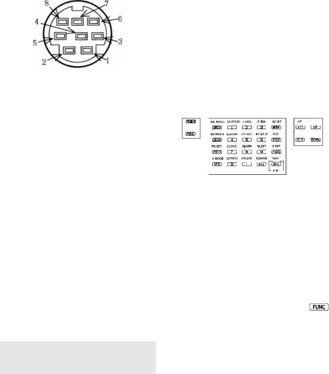
5-13 Front panel keys
 - POWER
This rectangular shaped plastic key located in the upper left corner of the front panel switches the set On/Off.
 - FUNCTION
This key is located to the upper left of the front panel and selects SECOND FUNCTION of the front panel keys. When pressed a reverse “FUNC” appears in the top left of the LCD. The FIRST function of the keys are printed on their faces (in orange for words and white for numbers), the SECOND functions are printed in white directly above the corresponding key.
For example, the select KEY LOCK, press followed by 
If you wish to cancel “FUNC” press  a second time, or
  or
or  or tune the receiver using the MAIN DIAL or SUB DIAL.
PAGE 10 AR5000 OPERATING MANUAL
 - SR.MODE
Pressing the  key places the receiver into program search mode. There are twenty search banks in total
numbered from 00 to 19. To change the bank number rotate the SUB DIAL, the bank number appears in the top
right of the LCD. If the receiver stops on an unwanted
busy channel during search, it can be forced onward using the 
 keys or MAIN DIAL. To cancel search
press  again or press
The key sequence 
 activates a sub menu where bank link, pause, delay, level squelch, voice squelch and auto-store may be configured.
 - SC.MODE
Pressing the  key briefly places the receiver into MEMORY RECALL MODE. The bank number may be selected using the SUB DIAL, channel number using the MAIN DIAL and three digit bank/channel number using the numeric keypad.
Pressing the  a second time places the receiver into memory scan mode. There are ten scan banks in total numbered from 0 to 9. If the receiver stops on an
unwanted busy channel during scan, it can be forced onward using the 
 keys or MAIN DIAL. To
cancel scan press  again or press
The key sequence 
 activates a sub menu where bank link, pause, delay, level squelch, voice squelch and mode may be configured.
 - PR.SET
The priority key  activates / deactivates receive PRIORITY as a toggle. The legend “PRIO” appears on the centre-top row of the LCD to show that priority has been activated and the legend “Pr” on the right of the LCD signifies when the priority frequency is currently active (busy).
If the sequence 
 is keyed, the channel used for priority may be selected followed by the interval for sampling, which is 5 seconds as default.
 - V.MODE
The AR5000 has a FIVE VFO system being identified “VA”, “ VB”, “ VC”, “ VD” & “ VE” on the right of the LCD.
The term VFO historically means Variable Frequency Oscillator and today refers to a tuneable data store which contains frequency, mode, step, attenuator and other relevant information.
The first time you enter a frequency via the numeric keypad, it is best to first press the  key until “VA” is displayed to place the receiver in a known state of operation. The condition of VFO (A-VFO), (B-VFO) etc is generally referred to as MANUAL MODE.
If the sequence 
 is keyed, additional parameters affecting VFO search operation may be configured: DELAY, L-SQ & VOICE.
 - SR.PROG
Figure ONE for the numeric input of frequencies, bank, channel numbers etc.
The sequence 
 activates the SEARCH PROGRAM menu where bank number, lower frequency limit, upper frequency limit, mode, and text comment may be programmed.
 - K.LOCK
Figure TWO for the numeric input of frequencies, bank, channel numbers etc.
The sequence 
 activates the KEY LOCK which
disables all front panel keys except for  and
and  , the rotary tuning controls (MAIN DIAL & SUB DIAL) are also
locked to prevent accidental misoperation of the receiver when listening to an important frequency. The volume and squelch controls remain operative.
The legend “KEY” is displayed on the top row of the LCD left of centre to indicate when key lock is in operation. To unlock the keys press 
 which acts as a toggle.
 - IF BW
Figure THREE for the numeric input of frequencies, bank, channel numbers etc.
The sequence 
 activates the I.F. bandwidth menu. In normal operation the word “AUTO” will be displayed toward the centre of the LCD to signify that automode is in operation and the I.F. bandwidth, receiver mode and channel step will be automatically selected by the receiver from its detailed pre-programmed bandplan data. Selecting a new bandwidth from the list of 220,
110, 30, 15, 6 and 3 kHz is accomplished using the SUB DIAL, 0.5 kHz is only available if the optional CW filter
has been fitted.
Once automode has been cancelled, it may be reinstated from the MODE select menu using a short cut... select AUTO by pressing and holding the  key for more than one second.
 - S.SCAN
Figure FOUR for the numeric input of frequencies, bank, channel numbers etc.
The sequence 
 initiates SELECT SCAN, a special form of scan where memory channels may be temporarily tagged in a form of notebook.
AR5000 OPERATING MANUAL |
PAGE 11 |

 - OFFSET
Figure FIVE for the numeric input of frequencies, bank, channel numbers etc.
The sequence 
 initiates FREQUENCY OFFSET where the receiver will automatically jump to a pre-programmed frequency offset, this is very useful for checking the other side of duplex transmissions such as the input frequency of amateur radio repeaters or VHF marine traffic.
The sequence  then hold the
  key for more than one second activates the FREQUENCY OFFSET menu where new offsets may be specified and saved / recalled from one of 48 special locations for easy retrieval at any time.
 - RF GAIN
Figure SIX for the numeric input of frequencies, bank, channel numbers etc.
The sequence 
 activates the RF GAIN control in place of the squelch control. The “N-SQL” legend is removed from the LCD to confirm operation. The RF GAIN control reduces the level of amplification applied to the receiver’s I.F. circuits. This has the effect of reducing the sensitivity of the receiver in much the same way as the attenuator but is more controllable.
The usual position for the AR5000 RF GAIN control is fully anti-clockwise when the set is at its most sensitive. As the control is rotated clockwise the S-meter will advance to indicate what strength signal is required to produce solid and readable results.
The control is most useful on SSB where the RF GAIN should be adjusted so that the peaks of SSB signals just deflect the S-meter. This will greatly reduce the level of background noise especially during pauses in speech or inactivity.
When the squelch control is switched off and RF GAIN used, the legend “N-SQL” is removed from the top line of the LCD slightly centre-right.
 - CLOCK
Figure SEVEN for the numeric input of frequencies, bank, channel numbers etc.
If the sequence 
 is keyed, the clock is displayed on the LCD. The SUB DIAL may be used to select one of
two clocks (a second clock is often useful to store world time of a regular DX site).
The sequence  then hold the
  key for more than one second activates the clock set menu where display of 12hr / 24hr may be selected, times set for both clocks and a three character text identifier added to each clock.
PAGE 12 AR5000 OPERATING MANUAL
 - ALARM
Figure EIGHT for the numeric input of frequencies, bank, channel numbers etc.
The sequence 
 activates the ALARM which can be programmed to switch the receiver on automatically as an alarm clock or for unattended recording with the provision to program the active period between 1 and 120 minutes.
The sequence  then hold the
  key for more than one second activates the alarm set menu.
 - SLEEP
Figure NINE for the numeric input of frequencies, bank, channel numbers etc.
The sequence 
 activates the SLEEP facility which can be programmed to switch the receiver off automatically after a prescribed time period of 1 to 120 minutes... useful if you go to sleep with the AR5000 as a bedside radio.
The sequence  then hold the
  key for more than one second activates the sleep set menu.
 - OPTION
Figure ZERO for the numeric input of frequencies, bank, channel numbers etc.
The sequence 
 activates the OPTION menu where the options of DTMF tone display and T-ELMT may be selected. If the optional boards are fitted, DE-SCR (descrambler, not available in all countries) and CTCSS tone selection may also be configured.
 - DELETE
Used during the MHz input of frequency to separate the MHz to the left of the frequency input from the rest of the entry of kHz and Hz. For example the entry of 88.300000 MHz would be 


Note: frequencies below 3.0 MHz (3000 kHz) are always displayed as kHz regardless of input format.
The sequence of 
 while in memory recall mode causes the displayed memory channel to be deleted.
The sequence  then hold the
  key for more than one second activates the DELETE menu where the item to be deleted may be selected:
MEM-CH |
memory channel |
SEL-CH |
select scan channel |
M-PASS |
memory channel pass |
SRCH |
search bank |
F-PASS |
frequency pass |

 - CONFIG
This key is used to accept frequency input via the numeric keypad in kHz format. For example: To key in a frequency of 954 kHz key 


 the LCD will display 954.000 kHz. This has the same effect as keying 0.954MHz or .954MHz
Note: keying a decimal  before the number causes a preceding zero to be added automatically.
The kHz method of frequency entry reduces the number of key presses required when working with low frequencies and simplifies operation as short wave listings are often stated in kHz. Example: Oceanic air traffic 5616kHz or short wave transmissions Radio Netherlands 5955kHz and 6045kHz.
The key sequence 
 activates the CONFIG menu where the lamp On/Off, keypad beep tone status OFF / volume, external IF output, remote baud rate, aerial (antenna) automatic switching and internal / external frequency reference may be configured.
 - AF.SET
This key is used primarily to select receive mode.
To select AUTOMODE press and hold the  key for more than one second, the receive mode, I.F. bandwidth and frequency step will be selected by the AR5000 automatically from its extensive pre-programmed bandplan listing.
When automode is in operation, the legend “AUTO” is displayed above the right hand digit (Hz position) of the frequency red-out.
To over-ride the receive mode, briefly press the  key. The options are: FM, AM, LSB, USB, CW and AUTO. WFM is supported as a product of the I.F. bandwidth selected (i.e. 110 or 220 kHz).
The key sequence 
 activates the AF.SET (audio frequency set-up) where the AUDIO LOW PASS FILTER (3.0 kHz, 4.0 kHz, 6.0 kHz or 12 kHz), AUDIO HIGH PASS FILTER (0.05 kHz, 0.2 kHz, 0.3 kHz or 0.4 kHz), AUDIO DE-EMPHASIS (25, 50, 75, 750 or THRU), CW PITCH (0.4 kHz, 0.5 kHz, 0.6 kHz, 0.7 kHz, 0.8 kHz, 0.9 kHz, 1.0 kHz or 1.1 kHz) and AUDIO INPUT (INTERNAL or EXTERNAL) may be configured.
 - AGC
- AGC
This key primarily selects the frequency step size for tuning the receiver. If the legend ”AUTO” is displayed then the step size will automatically be determined from the automode bandplan data, as soon as another selection is made automode is cancelled.
The standard step sizes offered for the MAIN DIAL are: 0.001 kHz (1 Hz), 0.010 kHz (10 Hz), 0.050 kHz (50 Hz), 0.100 kHz (100 Hz), 0.500 kHz (500 Hz), 1.000 kHz, 5.000kHz, 6.250 kHz, 9.000 kHz, 10.000 kHz, 12.500 kHz, 20.000 kHz, 25.000 kHz, 30.000 kHz, 50.000 kHz, 100.000 kHz and 500.000 kHz.
In addition unusual step sizes may be entered using the numeric keypad (i.e. 

 for 22 kHz or


 for 200 Hz).
The SUB DIAL may also be configured for: MAIN (same as MAIN DIAL), x10 speed of MAIN DIAL, 0.1 kHz, 0.5 kHz, 1.0
kHz, 5.0 kHz, 10.0 kHz, 50.0 kHz, 100.0 kHz, 500 kHz or 1000.0 kHz (1 MHz).
AGC
The key sequence 
 activates the AGC (Automatic Gain Control) menu.
In FM mode the options are AGC ON / OFF and in other modes are OFF, FAST, MIDDLE and SLOW. When AGC OFF has been selected, two horizontal bars are displayed on the LCD between the kHz and MHz legends.
FM: |
AGC |
OFF |
|
AGC |
ON |
Other modes: |
AGC |
OFF |
|
AGC |
FAST |
|
AGC |
MIDDLE |
|
AGC |
SLOW |
Note: “AUT” for AUTO AGC will be displayed toward the top right of the LCD if AUTOMODE is in operation and the appropriate AGC selection will be made automatically by the AR5000.
 - S.SET
This key is used to PASS (skip over) unwanted active frequencies in search and scan mode. In search mode, the unwanted frequencies are held in a special PASS LIST where they may be added to, deleted or reviewed. In scan mode the memory is locked out so is skipped.
The pass list is laid out in 20 banks for search mode (00 to 19) plus one extra for frequencies to be skipped while in VFO mode.
Pressing the  key while in memory recall mode or scan mode locks out the current channel so that it will be skipped over. The “PASS” legend is displayed to the left of the memory channel number (above the “M” legend) to signify that the channel is selected as PASS. The
  key acts as a toggle, simply press it again to remove the PASS status.
When the key sequence 
 is keyed while in SCAN mode or MEMORY RECALL mode, the displayed channel is added to the SELECT SCAN list. This is a special temporary notepad memory bank. The legend “S” is added to the display above the channel number, to the left of the bank number to signify that the channel is selected for SELECT SCAN (see section 10 of this manual).
Note: If this key is accidentally pressed, it may give the impression that the AR5000 is not receiving certain frequencies... so make sure you are familiar with the PASS operations.
AR5000 OPERATING MANUAL |
PAGE 13 |

The  key also allows selection On/Off of certain options while in menus (such as step-adjust) and selects defaults in other menus.
 - [MHz] [ENT] - TXT (Cyber Scan)
This key has three main applications:
MHz - the key is used to enter frequencies as MHz while in VFO mode. For example to enter a frequency of 88.300 MHz follow the key sequence 


 There is no need to add the trailing zeros to the right, once the
  key has been used, the AR5000
microprocessor will automatically add the additional trailing digits. The display will read “88.300000 MHz”
Note: Frequencies below 3.0 MHz (3000 kHz) will be displayed as kHz regardless of the entry format. It is usually more convenient to enter medium wave / long wave frequencies using the kHz format.
ENT - the key is used as ENTER in many operations and to complete sequences in most menus.
If the  key is held for more than one second while
in VFO mode, the receiver enters memory write mode. Use the MAIN DIAL to select channel number to be
overwritten, the SUB DIAL to select the memory bank number or key in the three digit memory location using the numeric keypad. Pressing the  ,
,  or
or  key will enable text comments of up to eight
characters to be added to each memory channel.
The key sequence  then press and hold the
  key for more than one second activates CYBER SCAN where scan and search speeds are approximately doubled (the frequency display is blanked out during CYBER SCAN
& CYBER SEARCH).
TEXT - The key sequence  then a brief press of
  causes the TEXT COMMENTS to be displayed in memory recall, scan and search modes
(in place of the frequency readout).
 - ANT
- ANT
This key activates the RF attenuator menu.
An aerial attenuator system allows selection of AUTO, 0dB, 10dB or 20dB. The attenuator control switches in / out of circuit the RF preamplifier and attenuator affecting the sensitivity of the receiver. 20dB may not be selected above 230 MHz. RF gain is also available in all modes via a front panel rotary control, this is especially useful in providing optimum audio quality for SSB operation.
The selection of attenuator is made using the SUB DIAL, the final selection is accepted by pressing the  key.
key.
The key sequence 
 activates the aerial selection menu. The SUB DIAL is used to select input via either of the two rear panel aerial sockets (ANT 1 for the N-type input and ANT 2 for the SO239). Additional aerials
may also be controlled via the optional AS5000 switching unit. AUTO may be selected where the aerial will be automatically switched based upon the programming of frequency / aerial data.
The sequence  followed by the
  key being held for more than one second activates the M.TUNE AUTO / MANU RF input preselection for frequencies up to 999.999999 MHz. The default is AUTO where the microprocessor controls the RF front end preselection. However if strong adjacent-channel interference is experienced, the preselection may manually moved off frequency reducing interference. Under this situation the on channel sensitivity will generally be reduced to some degree, for this reason do not manually tune the preselector too far away from the start point.
The 
 keys toggle between AUTO and M.TUNE with preselection being controlled by the SUB DIAL. To accept changes press
 - CLEAR
The CLEAR key may be used to abort frequency entry during programming or to escape from a menu. If the  key is held depressed while the receiver is switched on using the
  key, the AR5000 microprocessor will be soft reset.
 - UP
- UP
This key has three functions:
UP - if quickly pressed causes the displayed frequency in VFO mode to be incremented in an upward direction by one step. The key may be pressed to force the scan and search onward past a busy frequency or channel, it may also be used to reverse the direction of scan and search.
If held for more than one second while in VFO mode, frequency search is initiated. If held for more than one second while in memory recall mode, the scan process will start.
INCREMENT - the key will often increment menu options such as DTMF to T.ELMT etc. While in TEXT write mode, the  key will move the cursor one space to the right.
BACK SPACE - if an error is made while keying in frequencies in VFO mode, the  key may be used to back space delete the entry from the right hand side. If all digits are deleted, the display will return to the previous frequency.
 - DOWN
If this key is quickly pressed, the displayed frequency in VFO mode to be incremented in a downward direction by one step. The key may be pressed to force the scan and search onward past a busy frequency or channel, it may also be used to reverse the direction of scan and search.
PAGE 14 AR5000 OPERATING MANUAL
If held for more than one second while in VFO mode, a frequency search is initiated. If held for more than one second while in memory recall mode, the scan process will start.
INCREMENT - the key will often increment menu options such as DTMF to T.ELMT etc. While in TEXT write mode, the  key will move the cursor one space to the left.
Rear panel
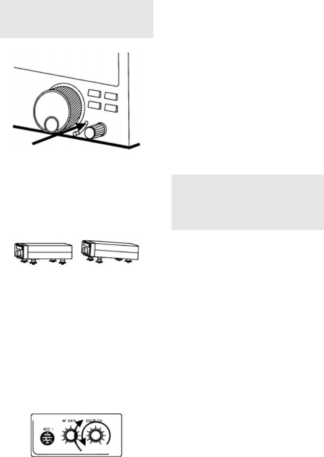
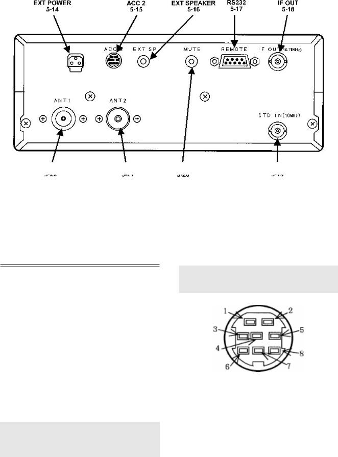
5-14 DC 12V - external power connection
This is a special three pin socket designed to accept external d.c. input of a nominal 13.5V d.c. @ 1.0A negative ground. You may either connect the power supply provided or another suitable supply such as a 12V car battery using the optional DC3000 d.c. lead and observing the correct polarity:
RED |
= |
positive |
WHITE (black on some cables) |
= |
negative |
Viewed from the rear of the receiver, the socket forms a pyramid of three terminals. The top is not used, the left is negative and the right positive. You need not worry about this in normal use as the special plugs are pre-wired and moulded onto the lead.
Note: At no time must a.c. mains power (100/110/120/ 220/230/240V a.c.) be connected directly to this socket or serious damage may occur including the risk of personal injury and fire.
5-15 ACC 2 (accessory 2 socket)
This 8-pin miniature socket is used for connection of an optional aerial (antenna) switching unit (AS5000) so that
more than two aerials (up to four) may be connected to the receiver and switched manually or automatically from the receivers front panel.
The optional AS5000 is connected to ANT 1 and the control switching signal is taken from ACC 2. ANT 2 is left unaffected and available for connection to an aerial leaving the AS5000 to provide access to ANT 1, ANT 3 and ANT 4.
Note: ACC 2 uses a different plug/socket to ACC 1. A typical example of the ACC 2 plug is manufactured by Hoshiden type TCP6180-01-1120.
Pin out is as follows:
112V 50mA MAX
210V 50mA MAX
3AGC 4.5 ~ 3.0V
4No connection
5ANT SW A (data line)
6ANT SW B (data line)
7No connection
8Ground
AR5000 OPERATING MANUAL |
PAGE 15 |

The control truth table is as follows:
Aerial |
number |
1 |
3 |
4 |
||
|
|
|
|
|
|
|
ANT |
SW |
A |
(data) |
|
G |
G |
|
|
|
|
|
|
|
ANT |
SW |
B |
(data) |
|
|
G |
|
|
|
|
|
|
|
Open collector 100mA MAX
(G) connects to ground
5-16 EXT SP - external speaker socket
This 3.5mm mono jack socket provides audio output to drive an external speaker unit. Connection to this socket automatically disables the internal speaker but not a headphone if connected to the front panel socket.
An external speaker should have a nominal 8 OHM impedance and power handling of 2 WATTS or greater.
5-17 REMOTE - RS232C computer port
The 9 pin female D type RS232C control socket and associated internal circuitry is fitted as standard. This permits the AR5000 to be connected directly to a computer for hands off remote control.
PC control Windows/95 software is under development for the AR5000 and a programmer’s RS232 command protocol supplement is available as an option.
Connection to an IBM compatible PC is as follows:
AR5000 |
PC 9-pin serial input |
|
|
|
|
2 |
2 |
|
|
|
|
3 |
3 |
|
|
|
|
5 |
5 |
(GROUND) |
|
|
|
7 |
7 |
|
|
|
|
8 |
8 |
|
|
|
|
AR5000 |
PC 25-pin serial input |
|
|
|
|
2 |
3 |
|
|
|
|
3 |
2 |
|
|
|
|
5 |
7 |
(GROUND) |
|
|
|
7 |
4 |
|
|
|
|
8 |
5 |
|
|
|
|
5-18 I.F. OUTPUT (10.7 MHz)
This BNC socket provides a suitable output to drive the optional AOR SDU5000 spectrum display unit providing a usable ± 5 MHz of bandwidth. The output to this socket
must be switched on using the CONFIG menu 
 , item three EXT-IF OFF, 1 or 2.
5-19 STD IN (10 MHz)
This BNC socket may be configured using the CONFIG menu 
 to accept an external high stability 10 MHz reference (such as off-air atomic coupled). In the standard configuration, a built-in 12.8 MHz TCXO is employed.
5-20 MUTE
This PHONO/RCA socket is used to mute the AR5000 when used in conjunction with a transmitter (to mute the AR5000 when placed into transmit). The transmitter should provide a normally closed contact becoming open during transmit.
Note: An internal yellow jumper wire is fitted across the mute terminals to enable normal operation without the need for a shorted phono/RCA plug to be fitted in place. If connected to a transmitter this yellow link wire must be cut. If the receiver is then to be used stand alone, a shorted plug MUST be left in the mute socket for standard operation or the AR5000 will not receive and no audio will be heard from the speaker.
In receive mode: |
Short circuit |
In transmit mode (muted): |
Open circuit |
Enabling the mute facility
Only the upper case of the AR5000 need by removed to access the area containing the yellow jumper wire. Switch the receiver off and unplug the power cord.
1 In order to lift the upper case, carefully (with the correct fitting posi-drive screwdriver) remove the 4 screws from the top cabinet and the 3 screws from each side panel (the screws on the side of the unit toward the front are larger than the rest). The rear edge of the top cabinet has a flange and the sides have two unused holes (for mobile mounting).
2Locate and cut the yellow jumper wire positioned above the MUTE terminal.
3Refit the upper case.
PAGE 16 AR5000 OPERATING MANUAL
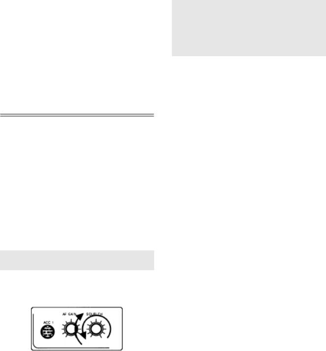
5-21 ANT 2
This is the secondary aerial (antenna) input for the AR5000 receiver. It may be controlled from the front panel or programmed to switch automatically.
The socket is a 50 OHM SO239 type and the corresponding plug is the PL259. Many off the shelf inter-series adapters are available for connection to BNC, N-type or other types of aerial termination.
5-22 ANT 1
This is the primary aerial (antenna) input for the AR5000 receiver. It may be controlled from the front panel or programmed to switch automatically.
The socket is a high quality 50 OHM N-type. Many off the shelf inter-series adapters are available for connection to BNC, PL259/SO239 or other types of aerial termination.
(6) Basic manual operation of the receiver
To achieve the maximum use of the receiver’s performance and features, it is important to fully familiarise yourself with it’s operation through the use of this handbook.
Connect and select an appropriate aerial (antenna) to the ANT 1 input on the rear of the receiver. The selection of aerial depends upon your location and specific requirements but may include a dipole, discone, colinear or long wire. There is further aerial information in section 20 of this manual, if in doubt please consult your dealer.
Connect the AR5000 to an appropriate d.c. power source using either the supplied a.c. adapter or optional DC3000 d.c. lead.
Note: Never connect the AR5000 directly to the a.c. mains supply.
Before turning on the power switch, set the volume to the 10 o’clock position and squelch control to the 12 o’clock position.
6-1 Switching on for the first time
Press and release the  switch, the receiver will power up and the LCD back light will illuminate.
Press the  key a few times until the legend “VA” is displayed in the lower right corner of the LCD. Press and hold the
  key for more than one second so that the “AUTO” legend is displayed in the centre of the LCD above
the last right hand digit of the frequency readout (Hz position) to ensure the receiver is in AUTO MODE. This places the receiver into a known state of operation ready to accept frequency input, change of mode etc. As with all modern microprocessor controlled equipment, the AR5000 has enormous potential and capabilities.
Note: The AR5000 uses an EEPROM (Electronically Erasable Programmable Read Only Memory) for storage of memories and other parameters. A permanent storage EEPROM has the advantage of not requiring a back-up battery to maintain data even when the receiver is disconnected from a power supply. The EEPROM may be over-written many thousands of times.
6-2 Changing VFO
The term VFO historically means Variable Frequency Oscillator and today refers to a tuneable data store which contains frequency, mode, step, and attenuator information.
The AR5000 has a total of FIVE VFOs which store frequency, mode, tuning step, I.F. bandwidth, attenuator setting etc. VFO mode is selected using the  key. The currently active VFO is displayed in the lower right corner of the LCD as “VA”, “ VB”, “ VC”, “ VD” and “ VE”. To cycle through the five VFOs, press the
  key repeatedly until the desired VFO is displayed.
Each VFO can be used for tuning and keying frequencies, all can hold different parameters. This is useful for keeping one VFO on VHF airband (AM), one on VHF marine band (FM), one on 20m amateur band (USB) etc...
In addition, the five VFOs are assigned additional status:
VFO-A
VFO-B Manual search between VFO-A and VFO-B displayed frequencies
If an automatic frequency search is initiated with “VA” or “VB” displayed, the process will loop from the start frequency in VFO-A and search until it gets to VFO-B then loop back to the start frequency of VFO-A and repeat.
The key sequence 
 accesses a menu where the DELAY, L-SQ level squelch and VOICE options may be set up for search between VFO-A and VFO-B.
VFO-C
VFO-D Accept the frequency from the search mode
If a frequency is keyed in to VFO-C or VFO-D and the  key held for more than one second the search process will commence from the displayed frequency.
If  is pressed while in SEARCH MODE, the active frequency will be transferred to VFO-D, the AR5000 will switch to VFO-D automatically where you may monitor and tune from the selected frequency.
AR5000 OPERATING MANUAL |
PAGE 17 |
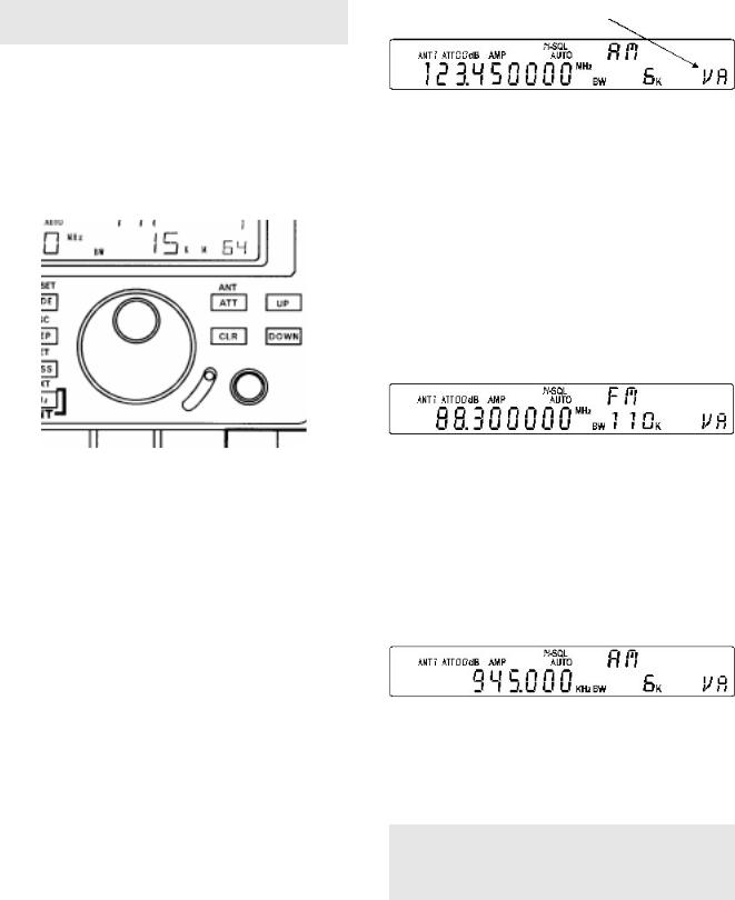
VFO-E Accept the frequency from the scan mode
If a frequency is keyed in to VFO-E and the  key held for more than one second the search process will commence from the displayed frequency.
If  is pressed while in SCAN MODE, the active frequency will be transferred to VFO-E, the AR5000 will switch to VFO-E automatically where you may monitor and tune from the selected frequency.
Note: If you press the VFO key for one second or longer, SEARCH will be activated.
6-3 Tuning the receiver using the rotary controls
The receiver may be tuned using the rotary tuning controls (MAIN DIAL and SUB DIAL) which are used to select receive
frequency and in memory mode for selection of memory channel etc.
A tuning knob is by far the most traditional approach to tuning on short wave, the MAIN DIAL provides a smooth
feel and the best method of user interface especially when listening on the SSB, FAX and CW modes. The SUB DIAL
is indented so tunes in a number of clicks and is best suited for channelised tuning on the VHF/UHF bands.
It is possible to tune the receiver through it’s entire range from 10 kHz to 2600 MHz. Rotating the MAIN DIAL &
SUB DIAL clockwise increases the displayed frequency (and tunes the receiver upward), rotating the controls anti-clockwise decreases the displayed frequency (and tunes the receiver downward).
The 
 keys may also be used to increase or decrease the receive frequency.
The AR5000 has an AUTOMODE capability where the receive mode, frequency step and I.F. filter selection is made automatically by the AR5000 microprocessor following detailed bandplan information (for each world market area). This very much simplifies and speeds up operation, particularly in the early stages of familiarisation.
When automode is active, the legend “AUTO” is displayed above the right hand digit (last one, Hz) of frequency readout. If it is not displayed, press and hold the 
key for more than one second, the “AUTO” legend will appear on the LCD to confirm selection.
6-4 Entering a frequency via the numeric keypad
Select VFO mode and the desired VFO out of the five available “VA”, “VB”, “VC”, “VD” and “VE”, this achieved by pressing the  key several times until the desired VFO is displayed on the lower right corner of the LCD (i.e. “VA”).
The AR5000 is now in a known state of operation ready for data input.
There are two methods of frequency entry, MHz & kHz:
MHz
The  key is used to enter frequencies as MHz while in VFO mode. For example to enter a frequency of 88.300 MHz follow the key sequence


 There is no need to add the trailing zeros to the right, once the
  key has been used the AR5000 microprocessor will automatically add the additional trailing digits. The display will read “88.300000 MHz”
kHz
The  key is used to accept frequency input via the numeric keypad in kHz format. For example: To key in a frequency of 954 kHz, key


 the LCD will display “954.000 kHz”. This has the same effect as keying 0.954MHz or .954MHz (Note: keying a decimal
  before the number causes a preceding zero to be added automatically).
The kHz method of frequency entry reduces the number of key presses required when working with low frequencies and simplifies operation as short wave listings are often stated in kHz. Example: Oceanic air traffic 5616kHz or short wave transmissions Radio Netherlands 5955kHz and 6045kHz.
Note: Frequencies below 3.0 MHz (3000 kHz) will always be displayed as kHz regardless of the entry format. It is usually more convenient to enter medium wave / long wave frequencies using the kHz format.
PAGE 18 AR5000 OPERATING MANUAL
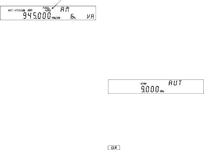
Providing the AUTOMODE facility has been engaged (so that the “AUTO” legend is displayed above the right hand digit of frequency readout), you may monitor the frequency or tune the receiver using the MAIN DIAL or SUB DIAL. The AR5000 microprocessor will automatically select the appropriate tuning increment, mode and I.F. bandwidth from the detailed automode bandplan data pre-programmed into the receiver (specific to each world market area). If automode is not active, press and hold the  key for more than one second. The “AUTO” legend on the LCD will confirm operation.
6-5 Correction of frequency during input via the numeric keypad
Should a mistake be made while entering frequency via the keypad in VFO mode, the  key may be used to backspace delete the entry from the right hand side. If all digits are deleted, the display will return to the previous frequency.
Most known step sizes are available with the exceptions such as TV channels which are allocated with 6MHz or 4MHz spacing. There will be occasions when you may wish to change the automode step selection so it is possible to customise the step size used by the MAIN DIAL and SUB DIAL (step size may also be programmed in search mode).
MAIN DIAL
Only when the VFO mode is engaged may the MAIN DIAL be used to select the receive frequency. Rotate the MAIN DIAL to change the receive frequency, alternatively the  and
and  keys can be used. Frequency will step in the pre-programmed step size as dictated by the automode bandplan data.
The  key enables the step size for tuning the receiver to be customised.
Press the  key, the flashing legend “STEP” on the LCD confirms that the STEP SELECT MENU has been activated. If the legend ”AUT” is displayed above-right, then the step will automatically be determined from the automode bandplan data. As soon as another selection is made automode is cancelled.
6-6 Selecting tuning step (increment)
The specification for channel occupancy, step (separation) and mode are decided by and allocated by departments of Government following International discussions.
Not surprisingly the allocation of frequency bands are not the same all over the world and channel separation (step) varies from band to band. As an example, the channel separation (step) for the medium wave band in Europe is 9 kHz while in the U.S.A. it is 10 kHz.
For the above reason it is necessary to alter the STEP size according to local bandplan conventions. The AR5000 has been pre-programmed at the factory with all the bandplan data (specific to each market area) so that the AR5000 will automatically select the appropriate step size and mode for the frequency chosen. This greatly simplifies operation of the receiver while you are familiarising yourself with all the facilities.
The pre-programming of step size may be manually overridden so you may choose alternative settings at will or when bandplans are updated.
The tuning step (often referred to as the tuning rate or increment) is usually automatically set by the AR5000 using the automode bandplan information - WHEN AUTOMODE IS ENGAGED.
To enable AUTOMODE, press and hold the  key for more than one second, the “AUTO” legend will appear on the LCD above the right hand (last) digit of the frequency readout to confirm selection.
At this point the SUB DIAL may be rotated to select a new step size for the MAIN DIAL from the following list: 0.001 kHz (1 Hz), 0.010 kHz (10 Hz), 0.050 kHz (50 Hz), 0.100 kHz (100 Hz), 0.500 kHz (500 Hz), 1.000 kHz, 5.000kHz, 6.250 kHz, 9.000 kHz, 10.000 kHz, 12.500 kHz, 20.000 kHz, 25.000 kHz, 30.000 kHz, 50.000 kHz, 100.000 kHz and 500 kHz.
Once the selection has been made press  to accept any changes. If you wish to abort step size selection press
In addition, unusual step sizes may be entered using the numeric keypad (i.e. 

 for 22 kHz or


 for 200 Hz). Acceptable input range is 1 Hz to 999.999 kHz.
Important: The receive frequency must be divisible by the step size or the receiver will not receive the desired frequency or follow the bandplan.
Examples:
Receive frequency / Step size must = round number
433.200MHz/20kHz = Divisible (433200 / 20 = 21660 all okay)
152.010MHz/20kHz = Not divisible (152010 / 20 = 7600.5 so must use the special STEP-ADJUST FACILITY detailed section 6-7 of this manual).
AR5000 OPERATING MANUAL |
PAGE 19 |
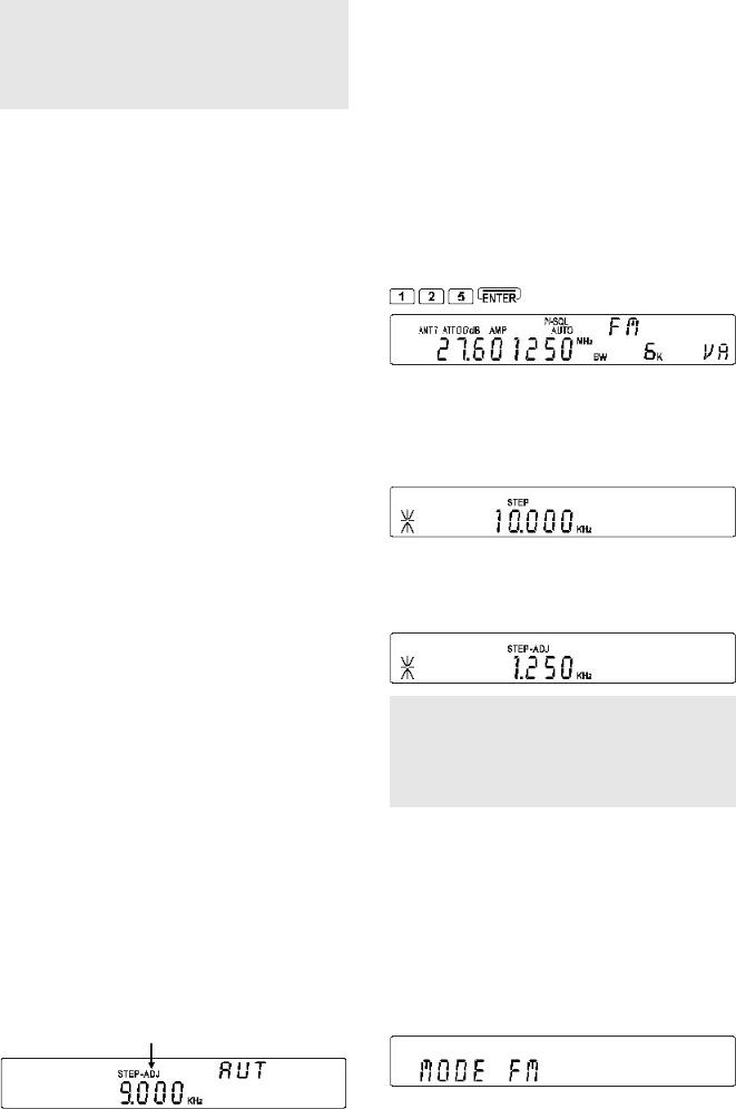
Note: The MAIN DIAL is a mechanical encoder and as such small variations in tuning may be experienced or the frequency may move slightly after rotation, this is normal. To ensure the best life span and smoothest operation, rotate the control from time to time to ensure the encoder’s track remains clean.
SUB DIAL
The SUB DIAL can also be used to select the receive frequency in three different ways:
lSame step size as the MAIN DIAL
l10 times faster than the MAIN DIAL
lOne of the step sizes from 0.1 kHz (100 Hz),
0.5kHz (500 Hz), 1.0 kHz, 5.0 kHz, 10.0 kHz,
50.0kHz, 100.0 kHz, 500.0 kHz or 1000.0 kHz (1 MHz).
The  key enables the step size for the SUB DIAL to be selected.
Press the  key, the flashing legend “STEP” on the
LCD confirms that the STEP SELECT MENU has been activated. The first menu is for the MAIN DIAL so press
 or
or  to move on to the SUB DIAL configuration (if step adjust is in use the legend “*” will be displayed and the
 keys will require two presses to
increment to the SUB DIAL menu). The flashing legends on the LCD “STEP” and “ SUB” indicate that the SUB DIAL
step selection menu has been activated. Use the SUB DIAL to make selection:
SUB MAIN
SUB x 10
SUB 0.1 kHz
MAIN = tuning rate for the SUB DIAL will be the same as that of the MAIN DIAL.
x10 = tuning rate of the SUB DIAL will be ten times faster
than the MAIN DIAL (i.e. a tuning rate on the MAIN DIAL of 25 kHz will be 250 kHz on the SUB DIAL).
0.1 kHz (100 Hz), 0.5 kHz (500 Hz), 1.0 kHz, 5.0 kHz,
10.0 kHz, 50.0 kHz, 100.0 kHz, 500.0 kHz, 1000.0 kHz (1 MHz) = tuning rates for SUB DIAL.
When the selection has been made, press  to accept the changes and return to VFO mode. If you wish to abort step size selection press
6-7 Step-adjust
The AR5000 provides a powerful feature to enable accurate following of unusual bandplans. When active, the “STEP-ADJ” legend is displayed in the centre of the LCD.
Step-adjust is used when the receiving frequency is not divisible by the step size in use (It is possible that stepadjust has been programmed into the automode bandplan data for some world market areas). Therefore step-adjust is useful for certain bandplans such as cellular which in some areas starts as 917.0125 MHz then increments in 25 kHz steps. Another example is the CB allocation in certain areas which starts at 27.60125 MHz then increments in 10 kHz steps.
Example:
Tune through the UK CB frequencies of 27.60125 MHz in 10 kHz steps with mode set to FM, 15 kHz bandwidth.
Select frequency: Select the start frequency for tuning, in this example 27.60125 MHz 


Set up step: Press the  key to access the tuning step menu. Select a step size of 10 kHz by pressing

 . Select STEP-ADJUST by pressing
  , the “*” legend is displayed on the left of the LCD to confirm operation. Complete the sequence by pressing
  .
.
You may review or change the offset value used by step-adjust via the STEP menu. Press  to access the tuning step menu. Initially the step size is displayed, press
  to view the STEP-ADJUST value.
Note: It is possible to enter a new value of step-adjust using the SUB DIAL and numeric keypad (i.e. 
 ) while viewing the step-adjust value, you can experiment with interesting results! If you intend direct programming please refer to the mathematical explanation at the end of this section 6-7.
Half step: If the original tuned frequency were a round number such as 145.000 MHz with a step size of say 25 kHz, the default step-adjust would be half of the original step size (12.5 kHz).
Press  to accept the data input and return to VFO mode. Alternatively press
  to abort entry and return to VFO mode.
Select receive mode: Press the  key and use the SUB DIAL to select “FM”. Press
  to accept the selection and return to VFO mode.
PAGE 20 AR5000 OPERATING MANUAL
Select receive bandwidth: For point-to-point communications a bandwidth of 15 kHz usually provides best results, however if adjacent channel interference is experienced a bandwidth of 6 kHz may provide better
results. Press 
 to access the I.F. bandwidth menu then use the SUB DIAL to make the selection (in this
example select 15 kHz). Press  to accept the selection and return to VFO mode.
If the MAIN DIAL is rotated the frequency will increment in 10 kHz steps but the trailing 1.25 kHz will remain in place...
27.60125 MHz, 27.61125 MHz, 27.62125 MHz etc. The trailing digits will not be set to zero enabling tracking of unusual band plans.
The MAIN DIAL follows the adjusted frequency bandplan while the SUB DIAL kills the trailing digits and steps rigorously in round numbers.
To cancel step-adjust
The easiest way to cancel step-adjust is to return to AUTOMODE, press and hold the  key for more than one second. Step-adjust will be cancelled and the frequency will hop to the nearest whole increment as determined by the automode bandplan data.
You may also cancel step-adjust using the STEP MENU. Press  to activate the step menu. If step-adjust is active, the legend “*” will be displayed on the left of the LCD. Press
  to toggle the step-adjust facility On/ Off. To accept the change to OFF, press
  to return to VFO mode.
Another example:
If the frequencies you need to search are allocated as:
145.210 145.224 145.238 145.252 145.266 145.280
145.294 145.308
Check the stepping size at first:
145.224 - 145.210 = 0.014 STEP SIZE
To enter this step size and data using the easiest method!
First key in the start frequency while in VFO mode:
Select the step menu by pressing 
Key in the required step size: 


Select step-adjust by pressing the  key, the legend “*” appears on the left of the LCD to confirm selection. Complete the entry by pressing
The MAIN DIAL will now tune the receiver in 14 kHz steps with the trailing offset maintained. The SUB DIAL tunes the receiver in 14 kHz steps but clears the offset to a round number (i.e. zero).
Note: You may review the step-adjust value quite simply...
While in VFO mode, press  followed by
  to access the step-adjust sub menu. In the above example the step-adjust value will be 2.0 kHz, refer to the following text for the mathematical explanation... this is not essential but makes good bedtime reading!!!
Application of arithmetic for the step-adjust
For those who wish further information on the mathematics involved... the AR5000 works this out for you automatically! The following examples should explain how the step-adjust works in theory.
If the frequencies you need to search are allocated as:
145.210 145.224 145.238 145.252 145.266 145.280
145.294 145.308 (MHz)
Check the stepping size at first:
145.224 - 145.210 = 0.014 STEP SIZE (MHz)
Now you have found that each frequency is allocated with a 0.014 MHz (14kHz) spacing you now have to calculate the value of the internal processing frequency:
145.210 / 0.014 = 10372.14285
This should be rounded as 10372 INTERNAL
PROCESSING VALUE
To obtain the internal processing frequency, multiply the STEP SIZE by the INTERNAL PROCESSING VALUE:
0.014 x 10372 = 145.208 INTERNAL PROCESSING FREQUENCY (in MHz).
Now calculate the STEP-ADJUST VALUE by subtracting the INTERNAL PROCESSING FREQUENCY from the DESIRED FREQUENCY:
145.210 - 145.208 = 0.002 (MHz) = 2 kHz
STEP-ADJUST VALUE
It can be concluded that a step-adjust value of 2 kHz is required.
In order to step through the above frequency allocation you need to apply a STEP SIZE OF 14 kHz with a 2 kHz STEP-ADJUST.
To apply a step size of 14 kHz and step-adjust of 2kHz:
Select VFO mode by pressing  , select the desired VFO (displayed in the right hand lower corner of the LCD).
Press  to activate the STEP select menu.
Press  to select STEP-ADJUST. The legend “*” will appear on the left of the display to confirm selection of step-adjust.
Key in the required step size for tuning (14 kHz in this example) by pressing 


Press the  key to select the step-adjust entry menu. The “STEP-ADJ” legend will flash in the middle of the
AR5000 OPERATING MANUAL |
PAGE 21 |

LCD inviting you to enter the value for step-adjust (2 kHz in the example). Press 

Press  once more to return to VFO mode. You will note the static legend “STEP-ADJ” to confirm that step-adjust is in operation.
Key in the start frequency (145.210 MHz in this example) by pressing 


 . Change frequency using the MAIN DIAL,
  or
or  keys to confirm correct operation.
6-8 FREQUENCY OFFSET
This facility enables receive frequency to be quickly SHIFTED (two key presses) by pre-determined margin, which makes it easy to track duplex-transmissions or check repeater inputs / outputs.
Offset frequencies may be factory pre-programmed into the automode bandplan data for some world market areas. Frequency offset may also be programmed manually.
Setting up an OFFSET FREQUENCY
Before the FREQUENCY OFFSET facility can be used, it first needs to be configured (unless factory programmed for certain bands).
1. To activate the frequency offset set-up menu press  then press and hold the
  key for more than
one second.
Example of display: |
|
OFF |
|
+ 45.000000 |
02 |
+ 0.600000 |
01 |
Offset frequency can be selected between the ranges of 0 to 999.999999 MHz and OFF. Available offset frequencies can be allocated into special storage locations numbered from 01 to 47. Number 00 is always treated as OFF and cannot be overwritten.
Locations 20 to 47 are reserved for factory preprogramming. These locations may be recalled and the positive / negative frequency shift altered using the  key but new numeric frequency offsets may not be stored.
Locations 01 to 19 are available for the operator to store new frequency offsets.
00 OFF
01 ~ 19 Available for storage of new offsets
20 ~ 47 Reserved for factory pre-programming
Having a number of frequency offset set-ups programmed ready for retrieval makes the facility even more useful when changing between frequency bands which have different duplex or repeater frequency offsets.
2.While the “FR-OFS” legend is flashing on the display
to indicate that the frequency offset menu has been selected, rotate the SUB DIAL to select a new (blank) location (i.e. 02).
3.Enter the offset frequency via the numeric keypad in MHz (i.e. for 600 kHz press 

 . The LCD will return to VFO, MEMORY, SCAN or SEARCH mode, whichever was previously in use.
4.If editing a previously stored offset frequency it is possible to select whether the offset should be up (+) or down (-) from the displayed frequency. If the frequency entered was new, simply re-enter the setup mode by
pressing  then holding the
  key for more than one second. Press
  to toggle the direction of the offset either “+” or “ -”, confirmation will be displayed on the LCD. To accept any changes press
Note: The direction of frequency offset “+” or “ -” selected using the  key has global effect on all OFFSET locations. The default is “+”.
Activating frequency offset
To activate frequency offset press 
 . The legend “FR-OFS” will be displayed on the LCD above the “MHz” legend to confirm operation. The displayed receive frequency will change to reflect the offset value and the receiver will monitor the new displayed frequency.
To deactivate frequency offset key 
 again, the “FR-OFS” legend will be removed from the LCD and the receiver will revert to the original frequency. See above (item 4) for selection of “+” or “ -” offset.
Note: The use of frequency offset will take the AR5000 out of automode. To reactivate automode press and hold the  key for more than one second, the legend “AUTO” appears on the LCD to confirm that automode has been reactivated.
Frequency offset with memory channels
All of the above may appear rather long-winded, however the facility comes into its own when the frequency offset is stored into memory along with other data such as receive frequency, mode etc during normal memory write (see section 7 of this manual), no special sequence is required. When written to memory both the frequency offset and direction of offset are stored for quick recall.
6-9 Changing receive mode (AUTOMODE)
As mentioned earlier in this manual, the specification for step and mode are allocated by departments of Government following International discussions. Like step size, the receive mode has been pre-programmed at the factory to simplify operation of the receiver while you familiarise yourself with all the facilities.
Should you wish, the defaults may be manually overridden at any time so that an alternative receive mode can be
PAGE 22 AR5000 OPERATING MANUAL
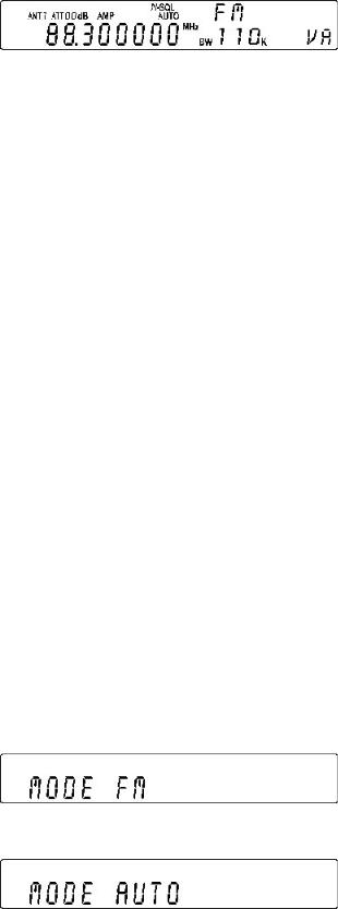
used on any frequency within the set’s range.
In normal operation AUTOMODE should be used. The legend “AUTO” is displayed above the right hand (last) digit of the frequency readout when automode is in operation.
Activating AUTOMODE
To activate automode, press and hold the  key for more than one second. The receive mode, I.F. filter bandwidth, step, step-adjust and frequency offset will then be automatically read from the automode bandplan data pre-programmed at the factory for each specific world market area.
Manually changing any of the parameters held by the automode bandplan data will cancel automode operation. To reinstate automode press and hold the  key for more than one second again.
Selecting automode will cancel any user defined items from the following list and select them automatically from the AR5000 bandplan data:
wReceive mode
wOffset frequency
wIFBW
wLPF
wHPF
wDe-emphasis
wTuning step
wStep-adjust
wAGC
The automode bandplan information can only be programmed at the factory or via a specialised computer program.
Manually changing receive mode
To change receive mode and override automode, briefly press the  key. The “MODE” legend will flash on the LCD to confirm that the mode select menu has been
activated. The following modes are available from the MODE menu: “AUTO”, “ FM”, “ AM”, “ LSB”, “ USB” and “CW”.
If automode is currently in use, the legend “AUTO” will be displayed on the LCD.
To escape from the menu press 
The SUB DIAL is used to change mode. When you have made your selection, press  to accept the new mode. The display will revert to VFO mode and the AR5000 will receive in the selected receive mode. Automode will have been cancelled and the “AUTO” legend will not be displayed on the LCD.
Each of the five VFOs (“VA”, “ VB”, “ VC”, “ VD”, “ VE”) can hold different modes, it is suggested that one be left on AUTOMODE for general tuning and others set to specific modes for specialist listening applications.
Remember: To reinstate automode press and hold the  key for more than one second.
Although any receive mode may be selected at any frequency within the receiver’s frequency coverage, generally speaking the following modes will apply:
AM
Amplitude Modulation - Used by broadcast services throughout the world on long wave, medium wave and short wave. AM is also used by VHF civil airband, UHF military airband and some PMR (Private Mobile Radio) and utility services.
FM
There are two common types of FM (Frequency Modulation), these are:
NFM - Narrow Band Frequency Modulation - this provides high quality communication for relatively short distance operation. FM uses a greater frequency bandwidth than other modes such as SSB so is less efficient.
NFM is the most common mode used above 30 MHz with the exception of the airbands. NFM is widely used on the VHF bands: VHF marine band, 2m amateur band (145MHz), 70cm amateur band (433 MHz), PMR (Private Mobile Radio) and utilities.
In the absence of a signal, the background white noise may appear quite loud. For ease of listening, the squelch control should be rotated clockwise until the background noise just disappears, this should be carried out while no signal is present. The point where the background noise is cancelled is known as threshold point. Do not advance the squelch control more than necessary or the receiver will appear to be desensitised and weaker signals will be missed.
WFM - The AR5000 does not list WFM (Wide Band Frequency Modulation) as a separate mode, it is simply a product of the I.F. filter bandwidth selection. Select a wide filter such as 100 kHz or 220 kHz and the receiver will use WFM.
Wide Band Frequency Modulation - used by VHF and UHF broadcast stations as excellent audio quality is available due to the relatively wide frequency bandwidth employed. Used only for local services such as VHF Band-II stereo (received as mono on the AR5000) and UHF TV sound channels.
AR5000 OPERATING MANUAL |
PAGE 23 |

LSB
Lower Side Band - is a form of Single Side Band (SSB). LSB tends not to be used commercially but is extensively used by Radio Amateurs on frequencies below 10 MHz. This assists the separation of Commercial and Amateur users on traditionally shared bands and prevents them from speaking to each other.
SSB is a very efficient method of transmission as the unwanted second sideband and carrier have been removed. This allows the full transmitter power to be employed in carrying useful information within the wanted sideband. As a result, greater distances are possible on SSB and a smaller frequency bandwidth is required than most other modes.
The AR5000 uses true carrier re-insertion and a dedicated SSB I.F. filter so that voice becomes intelligible. However due to the complexities of SSB, audio never sounds 100% natural and often listeners comment on it sounding a little like Donald Duck or Micky Mouse but this is normal and with practice you soon become used to this characteristic.
This is not a criticism of the AR5000 and is applicable to ALL SSB receivers in varying degrees... the AR5000 being very good.
Small tuning steps of 10 Hz (or 100 Hz at most) should be used for tuning in LSB and other similar modes USB & CW.
The SSB frequency display is not offset (like some other units). However being such a compact wide band receiver, it will not be unusual for the SSB display to be very slightly off frequency when listening to known frequencies such as VOLMET (airband weather forecast service).
USB
Upper Side Band - The same comments apply as for LSB. By convention, Radio Amateurs also use USB above 10MHz.
All long range shipping and oceanic air traffic (as well as long range military aircraft) use USB. DATA modes such as RTTY, SITOR, PACKET, FAX etc may be resolved using USB.
CW
Continuous Wave - Often referred to as Carrier Wave or Morse code (dots and dashes). Commonly used on the short wave bands by radio amateurs toward the lower end of each band allocation. Some commercial use is still made by shipping etc although its use is being phased out due to the introduction of automated stations. The AR5000 has the provision for the operator to select the frequency offset used by the receiver in CW mode using the AF.SET menu.
Note about AGC (Automatic Gain Control)
If the AGC is not set appropriately, audio will sound distorted. The key sequence 
 activates the AGC menu.
In FM mode the options are AGC ON / OFF and in other modes are OFF, FAST, MIDDLE and SLOW. When AGC OFF has been selected, two horizontal bars “=“ are displayed on the LCD between the kHz and MHz legends.
FM: |
AGC |
OFF |
|
AGC |
ON |
Other modes: |
AGC |
OFF |
|
AGC |
FAST |
|
AGC |
MIDDLE |
|
AGC |
SLOW |
Note: “AUT” for AUTO AGC will be displayed toward the top right of the LCD if AUTOMODE is in operation, the appropriate AGC selection will be made automatically by the AR5000.
6-10 IF BANDWIDTH
The I.F. bandwidth selects how SELECTIVE the receiver will be when monitoring signals off air. However it is not simply a case of using the narrowest filter at all times, particular modes require differing amounts of bandwidth in order to operate otherwise the receive system simply will not produce intelligible sound!
Correct receive mode and IF bandwidth must always be selected for optimum reception. If the bandwidth selection is too narrow, distortion or signal break-up may occur. If the bandwidth selection is too wide, adjacent interference may be encountered.
For this reason, a selection of I.F. filter bandwidths are fitted as standard. Typical examples of receive mode and IF bandwidth are:
FM 220kHz VHF FM broadcast (110k may also be used - mono only)
FM 110kHz TV audio (also VHF FM broadcast - in mono only)
FM 100 or 30kHz Wireless mic, etc (30kHz for satellite FAX too)
FM 15kHz PMR, amateur band etc FM 6 kHz may also be used
AM 6kHz VHF / UHF airband, short wave broadcast, medium & long wave, PMR etc
USB/LSB 3kHz Short wave amateur band, short wave utility such as oceanic airband etc
CW 3kHz (0.5kHz with optional filter fitted). Morse code used by radio amateurs and some marine traffic on short wave
An appropriate IF filter is automatically selected when automode is engaged. However any combination of IF filter and receive mode is possible in the MANUAL MODE. When you have manually selected an IF filter bandwidth, AUTOMODE will be disengaged, but the receive mode, stepping size, etc will be retained until they are changed manually.
PAGE 24 AR5000 OPERATING MANUAL
 Loading...