

AOR AR8200 Instruction Manual

Section 1
(1) AR8200 Index
(1) Index ............................................................................................................................ 1
1-1 Introduction .................................................................................................................. 5
1-2 Take care of your radio ................................................................................................ 5
1-3 Attention while operating ............................................................................................. 6
1-4 Accessories supplied ................................................................................................... 7
1-5 Controls & functions .....................................................................................................8
1-5-1 Keypad ..................................................................................................................... 9
1-5-2 Summary of keys ...................................................................................................... 10
1-5-3 Side panel ................................................................................................................. 15
1-6 Power supply and battery charging ............................................................................. 16
1-6-1 Internal batteries ....................................................................................................... 16
1-6-2 Charging the NiCads ................................................................................................ 18
1-6-3 Cigar lighter lead ...................................................................................................... 18
1-6-4 Battery considerations .............................................................................................. 19
(2) Making the AR8200 ready for operation ................................................................... 20
2-1 LCD (Liquid Crystal Display) ....................................................................................... 20
2-2 Connect the aerial (antenna) ....................................................................................... 21
2-3 Fit the batteries ............................................................................................................ 21
2-4 Keypad and knobs... what you need to know ‘most’ .................................................... 22
2-4-1 ENTER key ............................................................................................................... 22
2-4-2 FUNCTION key ......................................................................................................... 22
2-4-3 PASS key .................................................................................................................. 22
2-4-4 CLEAR key ............................................................................................................... 23
2-4-5 MONITOR key .......................................................................................................... 23
2-4-6 KEY lock ................................................................................................................... 23
(3) Basic manual operation of the receiver .................................................................... 24
3-1 Switching On ............................................................................................................... 24
3-2 2VFO twin VFO selection ............................................................................................ 24
3-3 Entering a frequency using the numeric keypad ......................................................... 26
3-4 Correcting frequency input .......................................................................................... 27
3-5 Changing frequency using the ñ and ò keys .............................................................. 28
3-6 Changing frequency using the main dial ..................................................................... 28
3-7 Changing receive mode ............................................................................................... 29
3-7-1 Auto-mode selection ................................................................................................. 29
3-7-2 Receive mode selection menu ................................................................................. 29
3-8 Changing tuning STEP size ......................................................................................... 31
3-9 STEP-adjust ................................................................................................................ 33
3-9-1 Automatic calculation of step adjust ......................................................................... 33
3-9-2 Cancelling step adjust .............................................................................................. 34
3-9-3 Manual setting of step adjust .................................................................................... 34
3-10 FREQUENCY OFFSET .............................................................................................. 36
3-10-1 Using pre-programmed frequency offset data ........................................................ 36
3-10-2 Entering new frequency offset data ........................................................................ 37
3-11 Attenuator .................................................................................................................. 38
3-12 Noise limiter ............................................................................................................... 38
3-13 AFC - Automatic Frequency Control .......................................................................... 39
(4) VFO enhanced facilities ............................................................................................. 41
4-1 Quick memories ...........................................................................................................41
4-1-1 Saving quick memory data ....................................................................................... 41
4-1-2 Recalling quick memories ........................................................................................ 42
4-2 VFO scan .................................................................................................................... 42
4-2-1 VFO SCAN sampling time ........................................................................................ 43
4-3 VFO Search ................................................................................................................. 43
4-3-1 Defining VFO search ................................................................................................ 43
1

4-3-2 Starting VFO search ................................................................................................. 43
4-3-3 Forcing VFO search to resume & changing search direction ................................... 44
4-3-4 Locking out unwanted frequencies (PASS) .............................................................. 44
4-3-5 Saving active frequencies to memory ...................................................................... 45
4-3-6 Exiting VFO search .................................................................................................. 46
4-4 VFO environment menu .............................................................................................. 46
4-4-1 VFO SCAN ...............................................................................................................46
4-4-2 VFO search DELAY environment ............................................................................. 46
4-4-3 VFO search LEVEL squelch environment ................................................................ 47
4-4-4 VFO search VOICE squelch environment ................................................................ 48
4-4-5 VFO FREE search environment ............................................................................... 48
4-4-6 VFO AUTO STORE environment ............................................................................. 49
4-4-7 VFO DELETE bank “J” environment ......................................................................... 49
4-4-8 VFO QUICK MEMORY environment ........................................................................ 50
(5) Memory channels & banks ........................................................................................ 51
5-1 Memory channel overview ........................................................................................... 51
5-2 Storing VFO frequencies & data into memory ............................................................. 52
5-2-1 Another example of memory write ............................................................................ 54
5-2-2 Automatic memory allocation ................................................................................... 55
5-3 Memory write protect ................................................................................................... 55
5-4 Memory read “M.RD” ................................................................................................... 56
5-4-1 Memory channel review / hunt ................................................................................. 57
5-5 Deleting memory channels .......................................................................................... 57
5-5-1 Memory channel editing ........................................................................................... 58
5-5-2 Adding text names to memory banks ....................................................................... 58
5-6 Transfer of memory channel to VFO ........................................................................... 58
5-7 Dynamic memory bank resizing .................................................................................. 58
(6) Priority operation ........................................................................................................ 59
6-1 Engaging PRIORITY channel ...................................................................................... 60
6-2 Changing PRIORITY channel data .............................................................................. 60
6-2-1 Changing the priority channel data pickup channel .................................................. 61
6-2-2 Changing priority interval time .................................................................................. 61
(7) SCAN - scanning memory channels & banks .......................................................... 62
7-1 SCAN - outline introduction ......................................................................................... 62
7-2 SCAN considerations .................................................................................................. 62
7-3 Starting to SCAN .........................................................................................................63
7-3-1 Transfer of active memory to VFO ........................................................................... 64
7-4 Selecting a scan bank ................................................................................................. 64
7-5 Channel PASS .............................................................................................................64
7-5-1 Toggling memory channel PASS .............................................................................. 65
7-5-2 Removing ALL memory PASS tags in one go .......................................................... 65
7-6 Deleting memory channels .......................................................................................... 66
7-6-1 Deleting single memory channels ............................................................................ 66
7-6-2 Deleting whole memory banks in one go .................................................................. 66
7-7 Scan bank link (scan group) ........................................................................................ 66
7-8 Additional scan facilities ...............................................................................................67
7-8-1 Scan DELAY .............................................................................................................68
7-8-2 Scan LEVEL .............................................................................................................68
7-8-3 Scan VOICE .............................................................................................................69
7-8-4 Scan FREE ............................................................................................................... 70
7-8-5 Scan (receive) MODE .............................................................................................. 70
7-8-6 Write protect of memory channels & banks .............................................................. 71
7-9 Select scan .................................................................................................................. 71
7-9-1 Adding select scan channels in memory read .......................................................... 71
7-9-2 Starting / stopping select scan ................................................................................ 71
7-9-3 Select scan environment .......................................................................................... 72
2

7-9-4 Editing the contents of the select scan list ............................................................... 72
7-9-5 Deleting all select scan channels ............................................................................. 73
(8) Search mode ............................................................................................................... 74
8-1 Search types ................................................................................................................ 74
8-1-1 Program search overview ......................................................................................... 74
8-2 Starting program search .............................................................................................. 75
8-2-1 Reversing the direction of search ............................................................................. 75
8-2-2 Forcing the search to resume ................................................................................... 75
8-2-3 Stopping the search ................................................................................................. 75
8-2-4 Copying an active frequency to the VFO or memory location .................................. 76
8-3 Selection of search bank ............................................................................................. 76
8-4 Programming a search bank ....................................................................................... 78
8-5 Locking out unwanted active frequencies (PASS) ...................................................... 80
8-5-1 Search pass menu ................................................................................................... 80
8-6 Search bank link .......................................................................................................... 81
8-7 Additional search facilities ........................................................................................... 82
8-7-1 Search DELAY ......................................................................................................... 83
8-7-2 Search LEVEL .......................................................................................................... 84
8-7-3 Search VOICE .......................................................................................................... 84
8-7-4 Search FREE ............................................................................................................85
8-7-5 AUTO STORE .......................................................................................................... 86
8-7-6 DELETE bank “J” ..................................................................................................... 86
8-7-7 Deleting search banks .............................................................................................. 87
8-7-8 Write protect and copying search banks .................................................................. 87
(9) EDIT menu ................................................................................................................... 88
9-1 EDIT COPY memory channel ...................................................................................... 88
9-2 EDIT COPY memory bank ........................................................................................... 89
9-3 EDIT COPY search bank ............................................................................................. 90
9-4 EDIT MOVE memory channel ...................................................................................... 90
9-5 EDIT SWAP memory channel ..................................................................................... 91
9-6 EDIT memory channel ................................................................................................. 92
9-7 EDIT Search protect .................................................................................................... 93
(10) DELETE menu facilities ............................................................................................ 94
10-1 DELETE search banks and search PASS frequencies ............................................. 94
10-2 DELETE VFO PASS .................................................................................................. 95
10-3 DELETE memory bank .............................................................................................. 95
10-4 DELETE select scan channels .................................................................................. 96
10-5 DELETE memory channel protect ............................................................................. 96
10-6 DELETE memory channel pass ................................................................................ 97
(11) Write protect ............................................................................................................. 98
11-1 Memory CHANNEL write protect ............................................................................... 98
11-2 Write protect during memory input ............................................................................ 98
11-3 Channel protect status for existing memory channels ............................................... 98
11-4 Channel protect delete ............................................................................................... 99
11-5 Memory BANK write protect ...................................................................................... 99
11-6 Search bank write protect .......................................................................................... 100
11-7 Global write protect .................................................................................................... 100
(12) TEXT search and input ............................................................................................. 101
12-1 Text input menus ....................................................................................................... 101
12-2 Text search ................................................................................................................ 102
(13) SHORT CUT keys ...................................................................................................... 103
13-1 Short cut menu access .............................................................................................. 103
13-2 Short cut text entry .................................................................................................... 104
13-3 Short cut text entry, keypad with ïðñò keys .......................................................... 105
3

(14) Configuration menu ................................................................................................. 106
14-1 CONFIG BEEP .......................................................................................................... 106
14-2 CONFIG LAMP .......................................................................................................... 106
14-3 CONFIG CONTRAST ................................................................................................ 107
14-4 CONFIG Power save ................................................................................................. 108
14-5 CONFIG Auto power off ............................................................................................. 109
14-6 CONFIG REMOTE BPS ............................................................................................. 109
14-7 CONFIG FREQ DISP ................................................................................................. 110
14-8 CONFIG GLOBAL write protect ................................................................................. 110
14-9 CONFIG Opening message ...................................................................................... 111
(15) Band scope ............................................................................................................... 112
15-1 Starting the band scope ............................................................................................. 112
15-2 Exit from band scope ................................................................................................. 11 3
15-3 Setting frequency span width (waveform enlargement) ............................................ 113
15-4 Moving the marker ..................................................................................................... 113
15-5 Marker to strongest signal (peak search) .................................................................. 113
15-6 Entering a new centre frequency ............................................................................... 114
15-7 Transfer of marker frequency to VFO ........................................................................ 114
15-8 Peak hold ................................................................................................................... 114
15-9 Saving active trace to memory .................................................................................. 114
15-10 Loading stored band scope traces from memory .................................................... 115
(16) Sleep .......................................................................................................................... 116
(17) Option socket ............................................................................................................ 117
17-1 RS232 operation ........................................................................................................ 118
17-2 CLONE of data via the option socket ......................................................................... 118
17-2-1 How to clone data ................................................................................................... 119
(18) Slot card socket ........................................................................................................ 121
18-1 Optional slot cards ..................................................................................................... 121
18-1-1 Fitting the slot card ................................................................................................. 121
18-1-2 Removing the slot card ........................................................................................... 122
18-2 VI8200 optional voice inverter slot card ..................................................................... 122
18-3 CT8200 optional CTCSS slot card ............................................................................. 123
18-3-1 CTCSS tone squelch .............................................................................................. 123
18-3-2 CTCSS search ........................................................................................................ 124
18-4 TE8200 optional tone eliminator slot card ................................................................. 125
18-5 RU8200 optional record & playback slot card ............................................................ 126
18-5-1 Recording ............................................................................................................... 126
18-5-2 Playback ................................................................................................................. 127
18-6 EM8200 optional external extended memory slot card .............................................. 127
18-6-1 Initialising (formatting) the EM8200 before use ...................................................... 128
18-6-2 EM8200 ALL-DATA save and load ......................................................................... 129
18-6-3 EM8200 ALL-MEM save and load .......................................................................... 130
18-6-4 EM8200 MEMORY BANK save and load ............................................................... 131
18-6-5 EM8200 ALL-SRCH save and load ........................................................................ 132
18-6-6 EM8200 SEARCH BANK save and load ................................................................ 132
18-6-7 EM8200 internally stored band scope save and load .............................................. 133
(19) Trouble shooting ....................................................................................................... 136
19-1 Soft reset of microprocessor ...................................................................................... 136
19-2 Other trouble shooting suggestions ........................................................................... 136
19-3 Trouble shooting - Take note of the following ............................................................ 137
(20) Optional accessories ................................................................................................ 138
(21) Aerial (antenna), earths & propagation ................................................................... 139
(22) Specification ............................................................................................................. 140
4

Section 1-1, 1-2
1-1 Introduction
Thank you for purchasing the AR8200 hand held wide band all mode receiver. The AR8200 is designed
using the very latest technology to ensure the highest levels of performance and reliability. To get the
best possible results from your AR8200 we recommend that you read this manual and familiarise
yourself with the receiver. Although carefully designed, this receiver (like all receivers) suffers from a
degree of internal noises known as spurii. They are a product of the receiver’s circuitry and do not
represent a fault. Apparent faults may be due to accidental misoperation of the receiver, if you think
there is a problem, carefully read all of the manual before deciding to contact your equipment supplier for
advice.
It is acknowledged that sections of this manual are repetitive, this is to enable the manual to be used as
a reference book (you don’t have to read it all from cover to cover in one go). Due to the international
nature of the product, some graphics contain Japanese characters.
Every effort has been made to make this manual correct and up to date. Due to continuous
development of the receiver and by error or omission anomalies may be found and this is
acknowledged.
© This manual is protected by copyright AOR Ltd 1998. No information contained in this manual may be
copied or transferred by any means without the prior written consent of AOR Ltd. AOR and the AOR
logo are trade marks of AOR Ltd. All other trade marks and names are acknowledged. E&OE
1-2 Take care of your radio
There are no internal operator adjustments. In the unlikely event of servicing being required, please
contact your dealer for technical assistance.
Do not use or leave the receiver in direct sunlight (especially the LCD). It is best to avoid locations
where excessive heat, humidity, dust and vibration are expected. Always keep the AR8200 free from
dust and moisture. Use a soft, dry cloth to gently wipe the set clean, never use abrasive cleaners or
organic solvents which may damage certain parts. Treat the AR8200 with care, avoid spillage or leakage
of liquids into the receiver and a.c. charger. Special care should be taken to avoid liquid entering around
the controls, through the speaker grille or via the connection jacks.
The AR8200 is designed for operation from internal batteries or from its supplied a.c.-to-d.c. charger.
Operation is possible from any good quality regulated d.c. supply of 12 to 14V, which should be capable
of supplying 300mA. Never connect the AR8200 directly to the a.c. supply.
The d.c. input socket uses a mini 1.3mm power connector. This connector is configured CENTRE
POSITIVE, the chassis of the receiver is at negative ground. The charger supplied is pre-wired and
provides a nominal 12V d.c. output with suitable connectors being fitted as standard for the a.c. power
input and connection to the AR8200.
SAFETY NOTICE - Always disconnect the charger from the a.c. socket when not in use.
If using the AR8200 in a base station situation, the best short wave reception is usually achieved by the
fitting of a separate external earth rod, however consider the implications carefully if your a.c. building
supply uses a Protective Multiple Earth (PME) system. If in doubt consult an expert electrician. Never
earth to a gas pipe!
The AR8200 has a single BNC aerial socket for all frequencies. This is intended for connection to its
supplied whip aerial or a 50 OHM (unbalanced) coaxial fed aerial such as a discone, dipole, unipole,
yagis etc. When sighting the aerial, avoid power cables.
5
Section 1-2, 1-3
Operating anomalies
Should the AR8200 appear to behave strangely, normal operation may be easily achieved by resetting
the microprocessor. Two scenarios may be encountered due to power transients etc:
1.
Symptom:
Action:
remove one NiCad battery and count to thirty! Re-fit the battery and press the power
switch again. Normal operation should be restored but the last used frequency will be
lost, the AR8200 will restore the last but one frequency to display.
2. Symptom: The AR8200 fails to power up.
Action: Try the suggestion given in (1) then hold the key while powering up
the AR8200 to ‘Soft reset’ the microprocessor.
LCD remains on, no control of the keypad.
Remove any connection to external power such as the charger or cigar lead,
1-3 Attention while operating
1. Certain key operations are acted upon when the key is RELEASED, not while it is pressed. Allow
time for the AR8200 to register such actions before pressing another key.
2. The keylock is intentionally made to be
To release keylock, the key has to be held for more than one second, the key legend on the
LCD confirms operation. The key is disabled during keying sequences (such as when
entering frequencies).
3. If a key sequence is not completed, the microprocessor will automatically abort most operations
after about 90 seconds of keypad inactivity.
4. Currently displayed VFO data is saved at power down (to increase speed of operation and to
reduce write cycles). For this reason, if the AR8200 is powered down by removing external supply
(without internal batteries in place or when the batteries become exhausted), the last displayed
frequency will be lost and the frequency used prior to this will be displayed when next powered up.
Terminology - Search & Scan
If you have not used a wide range monitor before or are not familiar with the terminology used, it is very
important to understand the difference between SEARCH and SCAN modes.
SEARCH: The AR8200 provides several operations where transmissions (active frequencies) may
be automatically located by sweeping the receiver over a wide frequency range, either from the
currently displayed frequency travelling upwards (or downwards) in a specified tuning increment
(step) or by sweeping over-and-over between two specified frequency limits. This process is known
as SEARCHING, as the title implies, it can take a long time to find transmissions due to their ‘often
intermittent’ and brief nature. For this reason it is best to slice large frequency ranges into smaller,
more manageable pieces where they may be intensively studied. When examining large frequency
bands, it is common to find that 90% of frequencies are inactive and only a small number of the
remaining constitute what you really want. Searching still remains the best way to initially locate
active and interesting transmissions (in conjunction with a good frequency listing and band plan).
SCAN: Once active transmissions have been identified (either by searching or by using a good
frequency guide), it is more efficient to store the data into memories which can be rapidly and
automatically monitored in succession stopping when activity is encountered. This forms a much
difficult to operate
to prevent accidental operation.
6
Section 1-3, 1-4
more efficient means of monitoring the most wanted frequencies as you have targeted 100% what
you most want to hear, by contrast searching is very inefficient for day-to-day monitoring.
&Note:
search & scan facilities to operate.
active frequency when the squelch opens and “S” ‘squelch open’ legend is displayed to the left
of the signal meter. Advance the squelch control clockwise until the background noise is just
cancelled, this is known as the threshold position. If the squelch control is advanced too far,
weaker signals may be missed.
It is very important that the squelch is advanced to cancel background noise for the
This is because the AR8200 believes that it has found an
No noise and no “S” legend (with squelch advanced clockwise passed
threshold) = squelch closed.
Signal received or ‘noise’ emanating from speaker (squelch fully anti-clockwise, below
threshold) with no “S” legend = squelch open.
1-4 Accessories supplied
The following items are provided in the carton box:
1 x AR8200 receiver
1 x Whip aerial in BNC connector
1 x Medium Wave (MW) bar aerial
4 x AA NiCad batteries
1 x Charger (may be supplied in a separate cartons in some world market areas)
1 x Cigar adapter lead (containing internal 1A fuse)
1 x Hand strap
1 x Belt hook with two screws
1 x Operating manual (this booklet)
How to fit the hand strap
The hand strap anchor is located on the right hand side of the
AR8200 cabinet. The hand strap comprises of two loops, one
large and one small. Feed the small loop through the anchor
then feed the large loop through the small loop and gently pull
until tight. This strap is designed to be looped over your wrist
to prevent the AR8200 from contacting the ground if
accidentally dropped, it is not intended as a hard wearing
utility… do not swing the set or abuse the set using this
hand strap.
The MW bar also has a fixing hole so that you may tie it
down to prevent loss.
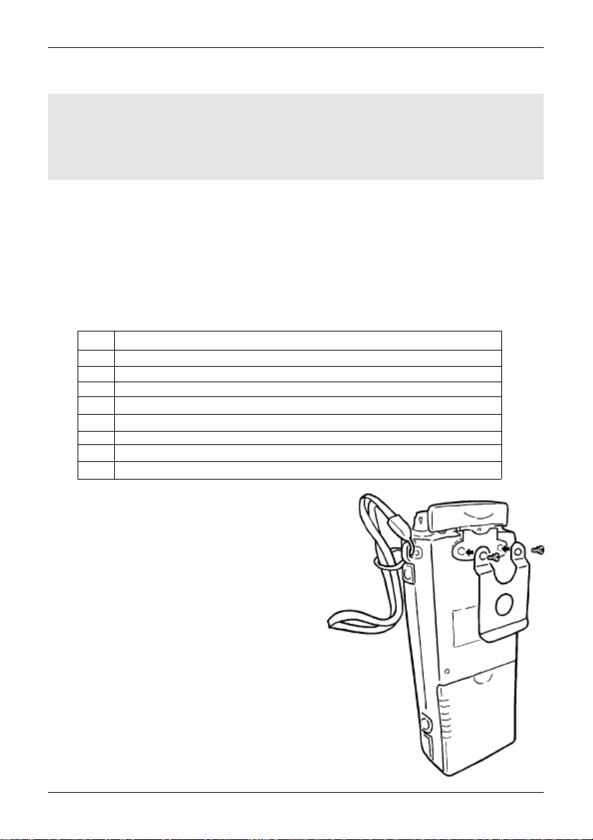
How to fit the belt hook
The belt hook is a shaped metal plate with two fixing holes on the top
edge, two fixing screws are provided. Do not use any other screws…
if you attempt to use longer screws, the internal parts may be permanently
damaged rendering the AR8200 inoperative. Offer the belt hook to the rear
of the AR8200, locate and align the fixing holes then carefully fit the two
supplied screws, fit both screws before tightening with a cross-head
screwdriver.
7
Section 1-5
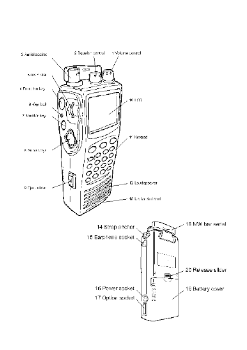
1-5 Controls & functions
Controls are located on the top, front and left hand side of the AR8200, a brief identification
is given here:
1. Rotary volume control
2. Rotary squelch control
3. BNC aerial socket
4. Function key
5. Main dial (thumb rotary)
6. Key Lock key
7. Monitor key
8. Arrow keys
9. Eject slider for optional SLOT CARD
10. LCD (Liquid Crystal Display)
11. Keypad
12. Loudspeaker
13. Lid for optional SLOT CARD
14. Hand strap anchor
15. Earphone / external speaker socket
16. External power / charging socket
17. Option socket
18. Medium Wave (MW) bar aerial
19. Battery compartment cover
20. Battery compartment release slider
8
Section 1-5-1
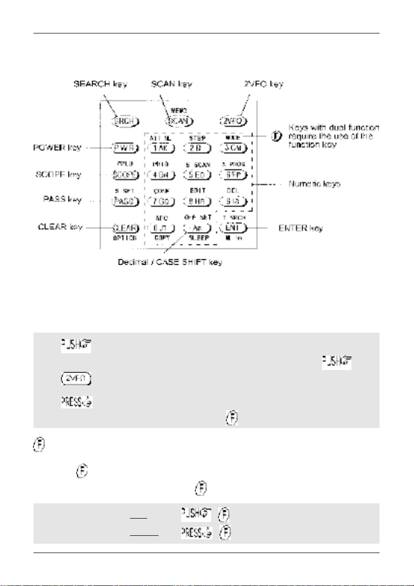
1-5-1 Keypad
Keypad conventions
Most keys have multiple functions, their functions are printed on the cabinet. However due the
restriction of available size, not all facilities can be shown on the keypad printing. To ease access to
the many facilities, two formats are employed:-
Push and release the key quickly to access the required facility. This applies to
primary facilities of keys such as numeric 1, 2, 3 etc. Also for example, quickly the
key while in 2VFO mode to toggle between the two VFOs VFO-A and VFO-B.
Press and HOLD the key for more than one second to access the second
function, sometimes this is in conjunction with the key.
Function key manipulation
The key also may be used by PUSH and PRESS depending upon the specific
requirement, in most cases however the key will require a simple PUSH.
“FUNC” LCD legend
“FUNC” LCD legend
solid
flashing
=
=
9
Section 1-5-2
1-5-2 Summary of keys
The main keypad is located on the front cabinet of the AR8200 with other keys located on the left
hand side. When powered from internal batteries with the lamp configured to AUTO, the lamp will
automatically illuminate when keys are pressed and will stay illuminated for five seconds after the last
key press.
An optional CC8200 RS232 lead is required for computer control, the optional CO8200 lead is required
for copying data between two AR8200 radios, various optional SLOT CARDS are available which further
extend the AR8200 facilities (and menus).
PUSH this key to place the AR8200 into SEARCH mode, the LCD “SRCH” legend confirms operation.
to access the bank link menu where up to ten different selections of
linked search banks may be grouped, this is useful where a large frequency band has been split up into
smaller more manageable sizes for close scrutiny.
Additional search related parameters may be set up to optimise each search group independently using
this menu:-
DELAY OFF / HOLD / 0.1s to 9.9s (default = OFF)
LEVEL OFF / 1 to 255 (default = OFF)
VOICE OFF / 1 to 255 (default = OFF)
FREE OFF / 1s to 60s (default = OFF)
AUTOSTORE ON / OFF (default = OFF)
DELETE J (deletes the current data from bank J)
PUSH this key to place the AR8200 into MEMORY READ mode, the LCD legend “M.RD” confirms
selection. again to initiate SCAN, the LCD legend “SCAN” confirms selection
to access the bank link menu where up to ten groups of memories may
be selected to be scanned in succession, effectively forming one large scan bank. Additional scan
related parameters may be set up to optimise each scan group independently using this menu:-
DELAY OFF / HOLD / 0.1s to 9.9s (default = OFF)
LEVEL OFF / 1 to 255 (default = OFF)
VOICE OFF / 1 to 255 (default = OFF)
FREE OFF / 1s to 60s (default = OFF)
MODE SCAN ALL / WFM / NFM / SFM / WAM / AM
/ NAM / USB / LSB / CW (default = ALL)
to set the ratio of bank size between memory channels sharing a
common letter in upper and lower case.
10
Section 1-5-2
PUSH this key to place the AR8200 into 2VFO mode where you may receive spot frequencies and
‘generally monitor activity’. The LCD displays two lines of frequency readout, the upper (larger) being the
current receive frequency. The LCD legend “2VFO” confirms selection with each VFO being identified as
“V-A” and “V-B”.
again to toggle between VFO-A “V-A” and VFO-B “V-B”.
to initiate VFO search between the two displayed frequency limits set by VFO-A and
VFO-B, the legend “V-SR” confirms selection of VFO SEARCH.
to access the VFO MODE select menu where the following parameters
may be configured:-
VFO SCAN ON / OFF (default = OFF)
DELAY OFF / HOLD / 0.1s to 9.9s (default = OFF)
LEVEL OFF / 1 to 255 (default = OFF)
VOICE OFF / 1 to 255 (default = OFF)
FREE OFF / 1s to 60s (default = OFF)
AUTOSTORE ON / OFF (default = OFF)
DELETE J (deletes the current data from bank J)
QUICK MEMORY OFF / 10s to 990s (default = OFF)
PRESS this key to switch the AR8200 on and off as a toggle. To prevent accidental switch on and off,
the power key is placed between two ridges and has to be held for more than one second for the press to
be registered. The ridges also help location of the power key when operated in areas of low level
lighting.
PUSH this key to activate the band scope, the , or key to return to
normal operation.
&Note: Priority operation is disabled when the band scope facility is in use.
Traces will be overwritten as the band scope is written from left to right on the LCD. To build up a long
term activity display, to toggle the PEAK HOLD facility on / off, the LCD
legend “HLD” confirms operation.
The key sequence recalls a previously saved band scope trace.
PUSH this key to PASS (lockout) memory channels during memory read & scan mode and to PASS
(skip) unwanted frequencies in search mode. Also acts as select ON/OFF/DEFAULT toggle in various
menus.
11
Section 1-5-2
in 2VFO mode to access the VFO PASS menu which extends to include the
SEARCH bank pass edit menu.
in 2VFO, SEARCH or SCAN mode to access the SELECT SCAN edit
menu.
PUSH to abort entry via the keypad.
to select the optional SLOT CARD when fitted.
and HOLD the key while powering On the AR8200 to soft reset the microprocessor
should the AR8200 appear to behave strangely... no memory contents will be lost.
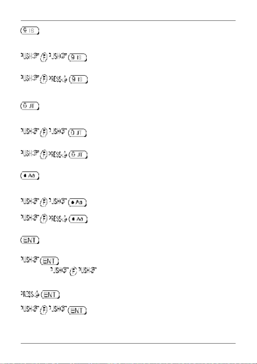
Numeric figure one during frequency input. Selection of memory/scan bank “A” or “a” and search bank
“A” or “a” or “K” or “k”.
to toggle the attenuator on / off, the LCD legend “ATT” confirms
operation.
to toggle the noise limiter on / off, the LCD legend “NL ” confirms
operation.
Numeric figure two during frequency input. Selection of memory/scan bank “B” or “b” and search bank
“B” or “b” or “L” or “l”.
to access the tuning STEP size (increment) menu.
Numeric figure three during frequency input. Selection of memory/scan bank “C” or “c” and search bank
“C” or “c” or “M” or “m”.
to access the receive mode selection menu.
to select AUTO-MODE where the receiver mode and tuning step are
automatically selected by the AR8200 microprocessor from the pre-programmed band plan data (this is
a short cut to save using the receive mode menu). The LCD legend “AUT” confirms that auto-mode is
in operation.
12
Section 1-5-2
Numeric figure four during frequency input. Selection of memory/scan bank “D” or “d” and search bank
“D” or “d” or “N” or “n”.
toggles the priority facility on/off (assuming that one has already been
assigned using the priority menu). The LCD legend “PRI” confirms when priority has been selected.
to access the priority menu where the data from a memory channel may
be assigned for priority use. The interval sampling time may also be specified.
Numeric figure five during frequency input. Selection of memory/scan bank “E” or “e” and search bank
“E” or “e” or “O” or “o”.
to initiate select scan (assuming that more than one memory channel
has already been tagged for select scan). The LCD legend “SEL” indicates when select scan is active.
or or to exit select scan.
Numeric figure six during frequency input. Selection of memory/scan bank “F” or “f” and search bank “F”
or “f” or “P” or “p”.
to access the program search menu where upper / lower frequency
limits etc for search mode may be entered.
Numeric figure seven during frequency input. Selection of memory/scan bank “G” or “g” and search bank
“G” or “g” or “Q” or “q”.
to access the configuration menu where the beep, lamp, LCD contrast,
RS232 etc. may be configured.
Numeric figure eight during frequency input. Selection of memory/scan bank “H” or “h” and search bank
“H” or “h” or “R” or “r”.
to access the edit menu when memory channels and search banks may
be amended and copy protection configured.
13
Section 1-5-2
Numeric figure nine during frequency input. Selection of memory/scan bank “I” or “i” and search bank “I”
or “i” or “S” or “s”.
will delete the currently displayed memory channel during memory read
or scan.
accesses the delete menu where search banks, VFO pass frequencies,
memory banks, select channel tags, channel protect status & memory pass tags may be deleted.
Numeric figure zero during frequency input. Selection of memory/scan bank “J” or “j” and search bank
“J” or “j” or “T” or “t”.
to toggle the AFC (Automatic Frequency Control) facility on/off, the LCD
legend “AFC” confirms selection.
to access the clone
Numeric decimal during MHz format frequency input. Used in memory and search as a CASE SHIFT
key to toggle between UPPER and LOWER case banks.
to access the frequency offset menu.
to access the sleep timer menu.
Used as an ENTER key to accept data entry.
during VFO operation to write the current frequency to QUICK MEMORY where the
key sequence ð recalls quick memory. The ïð keys may be used to cycle
through the quick memories, the LCD legend “«” indicates when a quick memory has been recalled.
to enter the current frequency in to one of the 1,000 memory channels.
to access the text search menu.
(copy between radio)
menu.
14
1-5-3 Side panel
The left hand side of the AR8200 comprises of three push keys, a nest of four
arrow keys and a rotary main dial. An eject slider is also provided to release the
optional SLOT CARD.
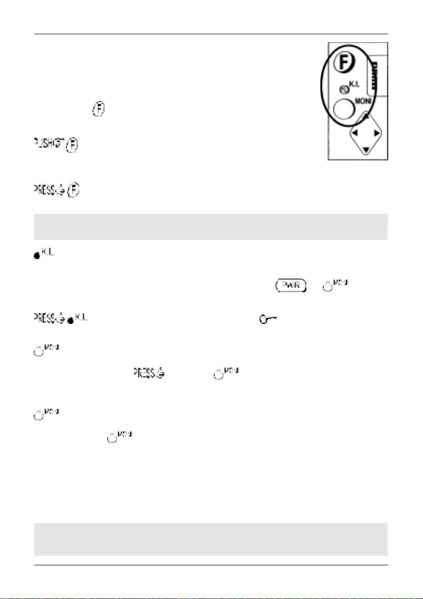
FUNCTION KEY
The function (shift) key is used to select the second function of keypad facilities.
to toggle the function status on/off. A solid reverse legend LCD
“FUNC” indicates when function shift is in operation. The function status is
terminated automatically in the normal course of entry.
Section 1-5-3
to initiate
“FUNC” legend flashes when
double-shift
double-shift
which is used in certain menus as a short-cut. The reverse
is engaged.
&Note: When the “FUNC” legend is displayed in VFO mode, the tuning speed will be
increased to assist rapid frequency change using the arrow keys and main dial.
The KEY LOCK is intentionally small to reduce the chances of accidental operation. Key lock is useful
when you do not wish an important frequency to be lost or the AR8200 to be incorrectly set to a different
frequency. The key lock status is
not affected by key lock.
to toggle the key lock on /off, an LCD key symbol “ ” indicates status.
The MONITOR key is used to force the squelch open so that you may manually intervene to ensure that
no weak signals are missed. and hold the key to defeat the squelch control (saves
turning the squelch control fully anti-clockwise then back to threshold position).
When the “DUP” legend is displayed during frequency offset or VFO SCAN (DUPLEX) operation, the
key forces the AR8200 to switch to the alternative frequency.
In SCOPE mode, the key enables the reception of the marker frequency.
MAIN DIAL
This recessed rotary control is intended to be scrolled up and down using the thumb of your left hand
(although you may adjust it using the middle finger of your right hand etc). Primarily this is the tuning
control, upward rotation tunes the AR8200 upward in frequency and downward rotation tunes downward
in frequency using the selected tuning step size. When the “FUNC” legend is displayed, the tuning
speed will be increased. The main dial is also used to move between menus and manipulate input
through menus (generally mimicking the arrow keys).
not
deactivated by switch off / on, the and keys are
&Note: The main dial also has a switch capability, this is why the main dial has lateral
movement. However, this switch capability is not used by the AR8200.
15
Section 1-5-3, 1-6, 1-6-1
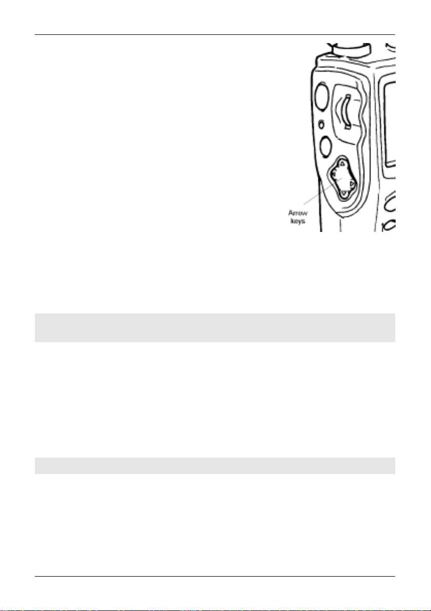
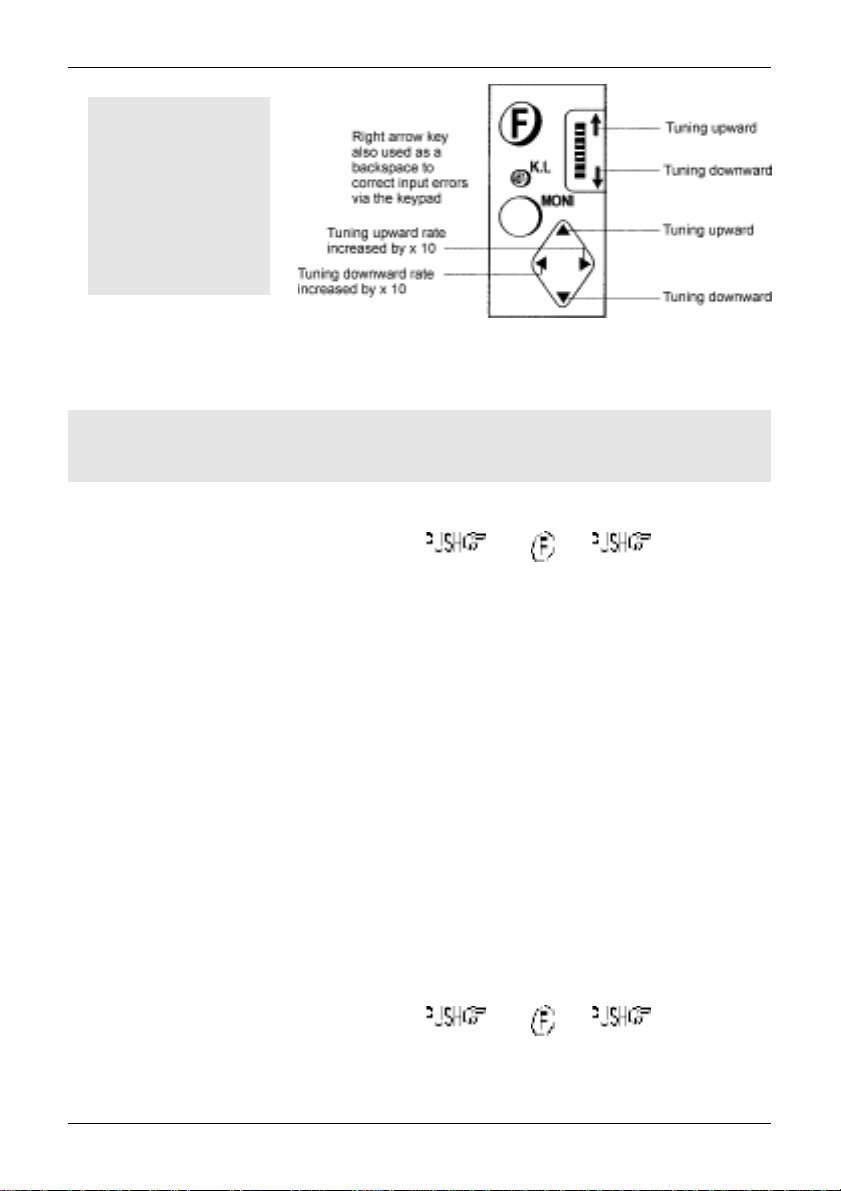
ARROW KEYS
The arrow keys ïðñò are laid out as a group of four keys (up, down, left
and right). This format is particularly convenient when used with the thumb of
the left hand (although you may use it with the middle finger of your right hand
etc) for navigation through on-screen menus.
ð
The right arrow key is used as a backspace when entering frequency via the
keypad. Also selects bank in memory read mode, moves the cursor position
(especially during text input), tunes the receiver and changes values in
menus.
ï
The left arrow key selects bank in memory read mode, moves the cursor
position (especially during text input), tunes the receiver and changes
values in menus.
ñ
The up arrow key increments to next memory channel in memory read
mode, tunes the receiver in VFO mode, selects menu items, changes
values in on-screen menus and forces scan & search to resume when
stopped on a busy channel.
ò
The down arrow key increments memory channel in memory read mode, tunes the receiver in VFO
mode, selects menu items, changes values in on-screen menus and forces scan & search to resume
when stopped on a busy channel.
&Note: It is possible to push two of the arrow keys at the same time (in error) by using
diagonal force, ensure that the arrow keys are operated cleanly and one at a time.
1-6 Power supply and battery charging
The AR8200 is designed for operation from internal batteries or from its supplied a.c.-to-d.c. charger.
Operation is possible from another good quality regulated d.c. supply of 12 to 14V, which should be
capable of supplying 300mA. Never connect the AR8200 directly to the a.c. supply.
The d.c. input socket uses a mini 1.3mm power connector. This connector is configured CENTRE
POSITIVE, the chassis of the receiver is at negative ground. The charger supplied is pre-wired and
provides a nominal 12V d.c. output with suitable connectors being fitted as standard for the a.c. power
input and connection to the AR8200.
SAFETY NOTICE - Always disconnect the charger from the a.c. socket when not in use.
If you are not going to use the AR8200 on batteries for a while, remove the batteries from the radio
(to prevent dry cells leaking) and charge NiCads before placing them into storage.
1-6-1 Internal batteries
The AR8200 is supplied with four AA size NiCad rechargeable batteries. These batteries are not
charged at the factory before shipping, so you will need to charge them before use.
16
Section 1-6-1
Dry cells such as Alkaline or Zinc / Manganese may be used but cannot be charged inside the
AR8200, if dry cells are fitted to the AR8200, remove dry cells before using the cigar lead or
connecting the charger or external power.
The AR8200 charging circuit is not designed to recharge dry cells or NiMHi batteries, if these are to be
recharged, they must be removed from the AR8200 and charged in a specialist external charger
following the manufacturers recommendations.
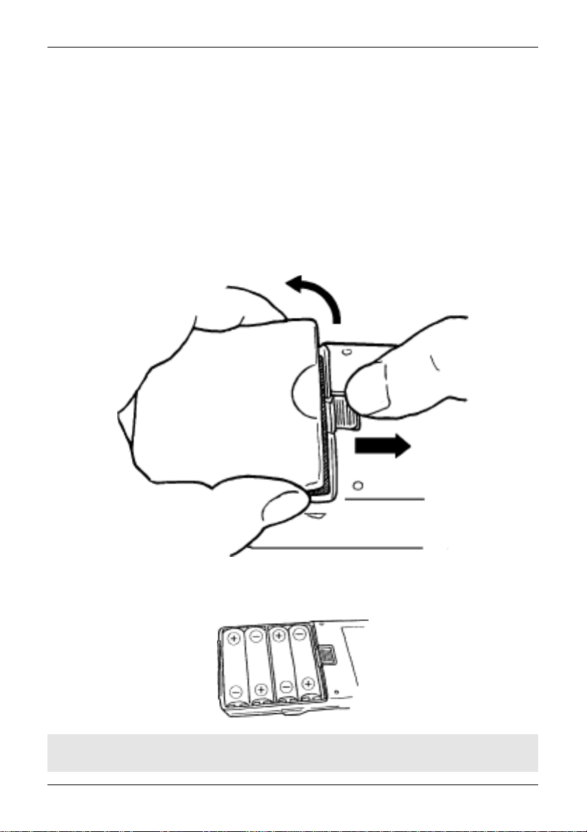
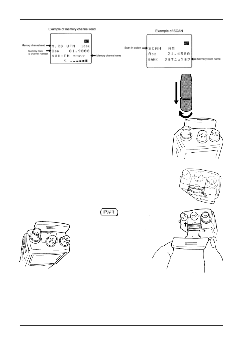
Fitting batteries
The battery compartment is located on the rear cabinet of the AR8200. A hinge is located at the bottom
edge with a ‘locking mechanism’ on the top edge of the compartment cover. To release the battery
compartment locking mechanism, slide the release upward (using a thumb is the best method) then lift
the compartment using a rotating action (using the thumb and forefinger of the other hand). Do not use
excessive force, the cover is completely detachable.
Insert the four NiCads supplied (or alternative AA sized batteries) observing the correct polarity
(head to toe positive / negative). Refit the battery compartment cover into the closed position.
&Note: Always switch the AR8200 off before fitting / removing batteries or when
connecting / disconnecting external power.
17
Section 1-6-2, 1-6-3
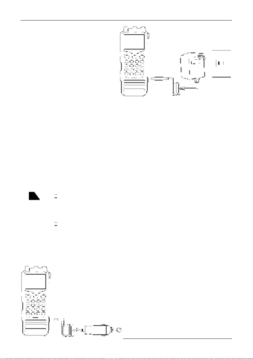
1-6-2 Charging the NiCads
It is possible to charge the supplied NiCad
batteries while still fitted inside the AR8200
using the charging unit provided. Switch off
the AR8200 then connect the plug from the
charging unit to the 12V d.c. input socket on
the right hand side of the AR8200 cabinet.
Connect the charger to the a.c. supply and
switch the power to the charger on.
When fully discharged, the NiCad batteries
will take 12 hours to fully charge while the
AR8200 is switched off. It is possible to charge
the AR8200 while the radio is switched on and being used, however the charging cycle will take longer
(16 hours is typical) and a degree of hum superimposed on reception may be encountered as the
charger is not regulated.
The AR8200 will provide around 4 hours of continuous operation with one third volume and constant
reception. The operational time between charges will be dependant upon volume level and operating
parameters, the power save facility will also extend operating time.
If connected to an external power supply, the AR8200 many be used for continuous operation.
When the NiCads near discharge, three states will be encountered:-
1. A battery symbol will appear in the extreme top right of the LCD a couple of minutes before the
NiCads completely discharge. The operational cut-off point is difficult to determine making advance
warning brief. The legend will have one diagonal bar representing minimal charge left.
2. The LCD battery legend will become an empty outline... operation will cease almost immediately.
3. The NiCads will expire and the set will power off (the VFO frequencies and last stored memory
may be lost). Connect the charger to continue operation or replace the exhausted cells.
1-6-3 Cigar lighter lead
It is possible to use the supplied cigar lead to charge the AR8200 NiCads and to power
the radio in exactly the same manner as the a.c. charger (except that it is connected to
a vehicle 12V d.c. supply). Ensure that the vehicle has a 12V d.c. battery, do not
connect to a truck / H.G.V. 24V battery.
The tip on the cigar plug is positive (+), the vehicle must be negative ground. A 1A
fuse is fitted inside the cigar lead, should this fuse blow for some reason, ensure it is
replaced with the correct type. Avoid short circuits.
Switch off the AR8200, connect the cigar lead to the
AR8200 12V d.c. input socket THEN connect the
cigar plug to the vehicle and switch the AR8200 on.
18

Section 1-6-3, 1-6-4
It is advisable to switch the AR8200 off when starting the vehicle as the starter motor often causes
power surges. Some vehicles require their ignition to be ON for the cigar socket to operate.
1-6-4 Battery considerations
The supplied NiCads are not factory charged. Fit them to the AR8200 and charge for about 12 hours.
After this time the NiCads should never be left in a flat condition or internal filaments will form (inside the
NiCads) shorting its terminals rendering it useless. If you are not going to use the NiCads for a while,
charge them before placing them into storage. NiCads have a memory effect, for longevity, once a
month flatten them completely then fully charge them again. Avoid excessive ‘topping up’, when
possible, it is best to charge NiCads when they are totally flat.
If you have not used the cells for a long time, specialist external chargers may help ‘bring them back to
life’ by first discharging them COMPLETELY then charging at a higher rate than the AR8200 can provide.
It is common practice to place exhausted NiCads into a torch to ensure that they are totally flat before
charging, this ensures the best life span. Regular charging in a rapid external charger may be
convenient but will reduce the life span of the cells.
Do not over-charge, charging for more than 24 hours may significantly shorten the life span of the
NiCads. If the NiCads are left charging permanently, there is a small chance of explosion due to the
build up of heat. If you intend permanently using the AR8200 from an external power supply, remove
one battery to prevent over-charging... or better still remove all the batteries and store them away.
Do not short NiCads as they can provide high current levels.
The supplied NiCads will typically provide around 300 charge / discharge cycles.
If dry cells are used (Alkaline, Zinc, Manganese) make sure they are removed if external power is
connected to the AR8200. Do not mix cells of different types and do not mix new and used cells.
19
Section 2, 2-1
(2) Making the AR8200 ready for operation
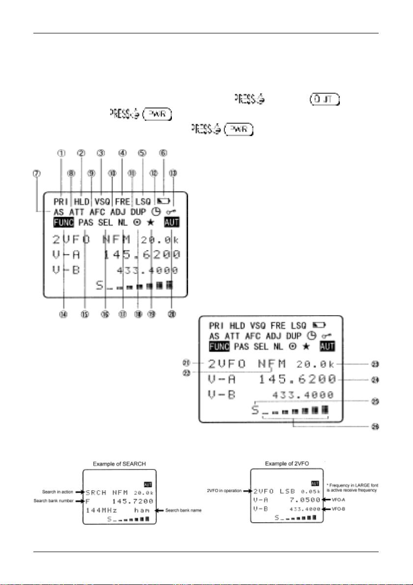
2-1 LCD (Liquid Crystal Display)
All relevant operational information is provided via the large LCD. To see all the available LCD legends,
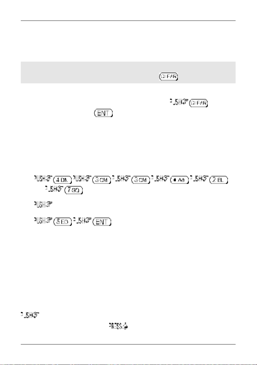
and to test the LCD, an LCD test routine has been provided. and hold the key then
switch the AR8200 on, . When the sign-on message has been displayed all LCD
graphics will be displayed. To exit the LCD test . The LCD contrast is adjustable
using the configuration menu as is the rear LCD & keypad illumination.
1 Priority
2 Search hold / band scope peak hold
3 Voice squelch
4 Free search / scan
5 Level squelch
6 Low battery
7 Auto store
8 Attenuator
9 Automatic Frequency Control
10 Step-adjust
11 Duplex
12 Sleep
13 Key lock
14 Function
15 Pass (lockout)
16 Select scan
17 Noise limiter
18 RS232 remote
19 Band scope peak
search / quick memory
20 Auto-mode
21 Operating mode (2VFO,
SRCH, SCAN etc)
22 Receive mode
23 Tuning step size
24 Active receive frequency
25 Squelch open legend
26 Signal meter
Typical examples of LCD:-
20
2-2 Connect the aerial (antenna)
Two aerials are supplied with the AR8200:
l BNC mounted whip aerial
l MW bar aerial
For general reception on the VHF/UHF bands, connect the supplied whip
aerial to the BNC socket on the top panel of AR8200. This is a bayonet
connector, line up the slots, press down firmly and twist clockwise, the
guides will position, then let go. A different aerial can easily be fitted once
you have established that the AR8200 is operating correctly and you are
familiar with operation.
If you wish to monitor MW (Medium Wave bands), plug in the MW bar aerial.
The MW slot on the top panel is protected by a sliding door to keep out dust
and rain. A cut-out on the rear edge of the top panel enables the sliding door to
be easily ‘swept’ open using a fingertip or thumb. Another cut-out toward the
centre of the top panel enables the sliding door to be easily
‘swept’ closed... No force is required !
Section 2-1, 2-2, 2-3
The MW bar is asymmetrical. With the longer arm of the MW bar facing to the
right (grooves to the front) locate the MW connector into the socket and push
into place. The force required to engage the MW aerials is quite small, about
the same as you would use to ensure the key is
pressed with a positive result. If you
really press very hard, it is possible
to force the connector in back-
wards... the MW aerial will not
operate if connected backwards.
Remember to close the MW slide
door when the MW bar aerial is
not in use.
2-3 Fit the batteries
Fit the NiCad cells or dry batteries to the AR8200 as detailed in
Alternatively the charger may be connected to the 12V d.c. socket of the AR8200 (however, do not
connect external power if dry batteries are fitted).
section 1-6-1
of this manual.
21
Section 2-4, 2-4-1, 2-4-2, 2-4-3
2-4 Keypad and knobs... what you need to know ‘most’
Several of the keys have special characteristics, a summary was given in
where it was explained that several keys have two of three functions associated with them.
section 1-5-1
of this manual
&IMPORTANT Note: Make sure you understand the PASS (LOCKOUT / SKIP) operation
before using the PASS facility, this applies to the PROTECT facility too, make sure both
facilities are understood
The list presented here represents ‘what you need to remember most’ ! Refer to
manual
for the definition of and should you not understand the syntax shown here.
before
you attempt to use them.
section 1-5-1 of this
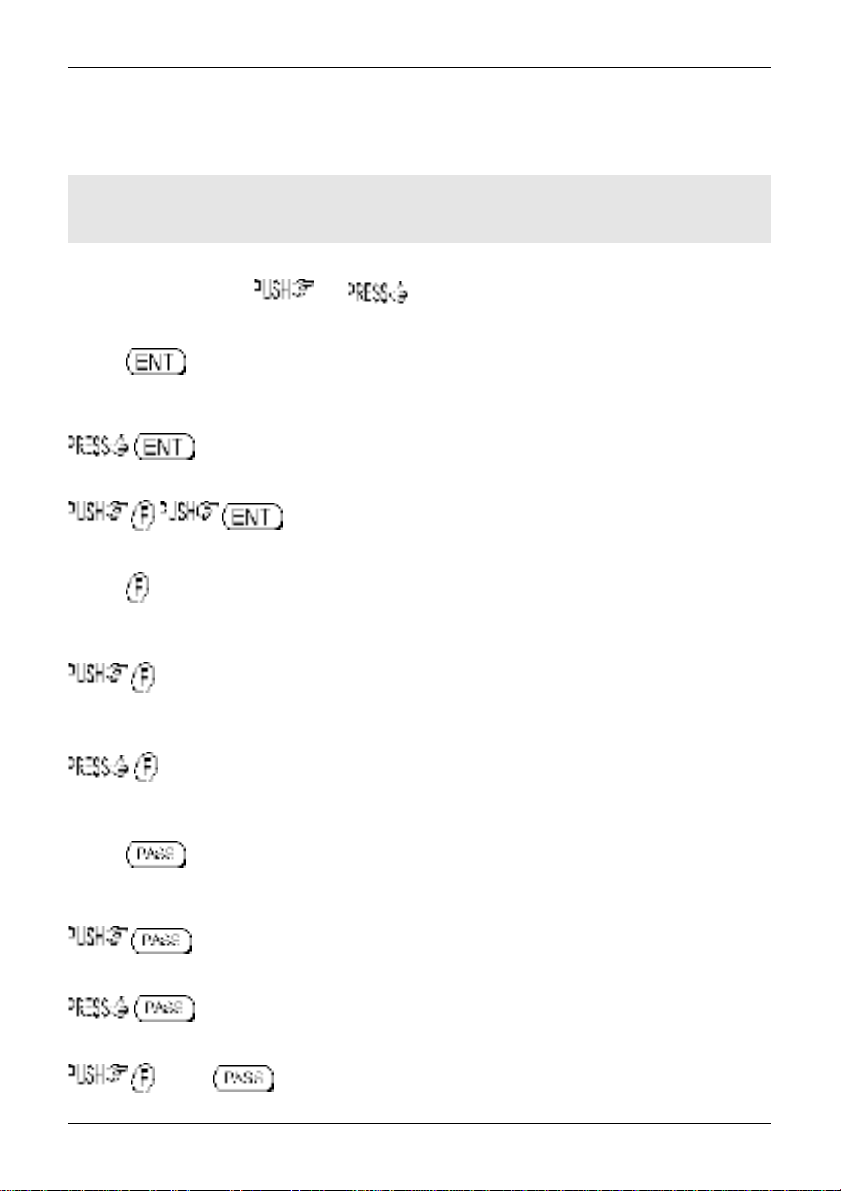
2-4-1 ENTER key
Used as an ENTER key to accept data entry.
to enter the current frequency in to memory (a quick memory facility is also available,
explained
section 4-1
to access the text search menu.
of this manual).
2-4-2 FUNCTION key
The function (shift) key is used to select the second function of keypad facilities.
to toggle the FUNCTION (shift) on/off. An solid reverse legend LCD “FUNC” indicates
when function shift is in operation. The function status is terminated automatically in the normal course
of entry.
to initiate double-shift which is used in certain menus as a short-cut. The reverse “FUNC”
legend flashes when double-shift is engaged.
2-4-3 PASS key
This key needs special attention as it acts as select ON/OFF/DEFAULT toggle in various menus.
key to PASS (lockout) memory channels during memory read & scan mode and to
PASS (lockout / skip) unwanted frequencies in search mode.
in 2VFO mode to access the VFO PASS menu which extends to include the SEARCH
bank pass edit menu.
PRESS in 2VFO, SEARCH or SCAN mode to access the SELECT SCAN edit
menu.
22
Section 2-4-4, 2-4-5, 2-4-6
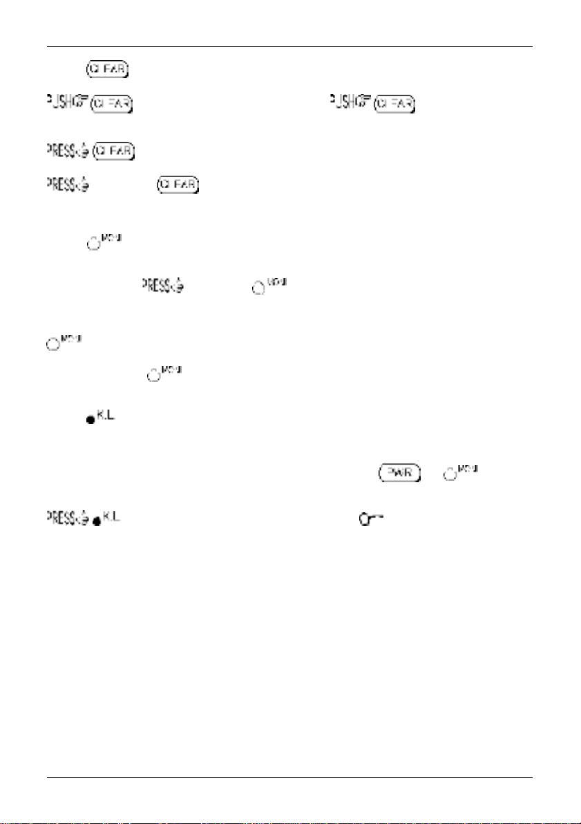
2-4-4 CLEAR key
to abort entry via the keypad... if in doubt, to return to the previous
display menu or operating mode.
to select an option when an optional SLOT CARD is used.
and hold the key while powering on the AR8200 to soft reset the
microprocessor should the AR8200 appear to behave strangely... no memory contents will be lost.
2-4-5 MONITOR key
The MONITOR key is used to force the squelch open to manually intervene ensuring that no weak
signals are missed. and hold the key to defeat the squelch control (saves turning the
squelch control fully anti-clockwise then back to threshold position).
When the “DUP” legend is displayed during frequency offset or VFO SCAN (DUPLEX) operation, the
key forces the AR8200 to switch to the alternative frequency.
In SCOPE mode, the key enables the reception of the marker frequency.
2-4-6 KEY LOCK
The KEY LOCK is intentionally small to reduce the chances of accidental operation. Key lock is useful
when you do not wish an important frequency to be lost or the AR8200 to be incorrectly set to a different
frequency. The key lock status is not deactivated by switch off / on, the and keys are
not affected by key lock.
to toggle the key lock on / off, an LCD key symbol “ ” indicates status.
23
Section 3, 3-1, 3-2
(3) Basic manual operation of the receiver
The following information explains how to tune to a specific frequency, change receive mode etc.
&Note: When the AR8200 is switched OFF, all VFO data will be automatically stored into
flash-ROM memory storage. No battery or capacitor is required for memory backup. Should
the NiCad cells (or dry batteries if in use) become completely exhausted, the last stored
memory channel or last VFO data ‘may’ be lost.
CURSOR
The CURSOR may apparently ‘go to sleep’ at times when menus are called. This is because of the
many tasks called by the microprocessor, it is simply doing something else at the time you call it. This
is particularly noticeable when recalling memory banks when only a few channels have been stored.
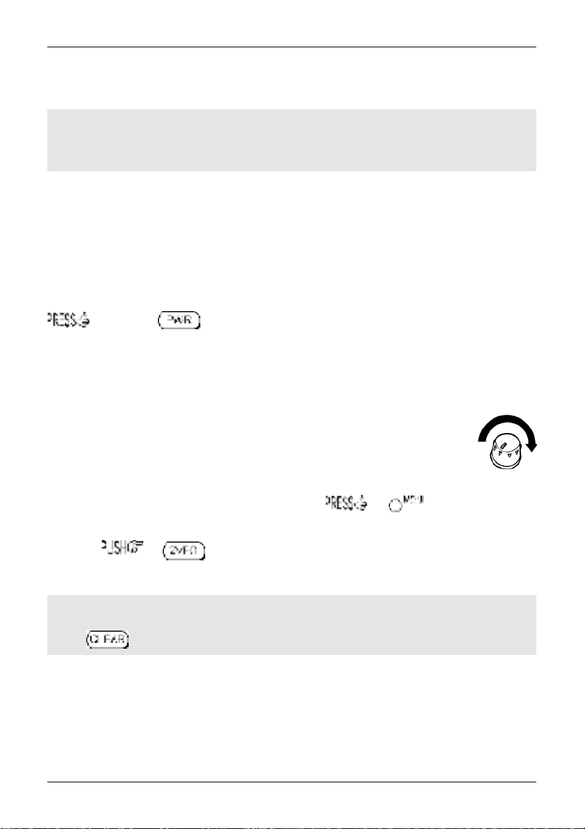
3-1 Switching On
Set the squelch control to the 12 o’clock position and rotate the volume control to the 12 o’clock position.
and hold the key until the AR8200 powers up. It is never a good idea to switch on
any receiver with an earphone connected, there may be an audible click when the unit is switched on or
the volume may be accidentally set uncomfortably high.
In the default state, the LCD will show the opening message “WELCOME TO THE NEW WORLD OF
AR8200” across the first four lines, at the same time the microprocessor generates the ‘boot up data’
required to control the receiver.
In normal use, the squelch control should be rotated clockwise until the background noise
is
just
cancelled, this is known as ‘
squelch control. Do not rotate the control too far clockwise or only the stronger local
signals will be heard. If you find setting the squelch control difficult, try removing the aerial
from the receiver.
threshold
’ and is the most sensitive setting for the
Should you encounter problems in setting the volume level, the key on the left hand
panel to momentarily defeat (open) the squelch so that a comfortable volume level may be set.
It is best to the key at this time to place the AR8200 in a known state of operation.
The condition of “VFO” (1VFO) or “2VFO” is generally referred to as
will be displayed in the upper left of the LCD to confirm selection.
manual mode
. The “2VFO” legend
&Note: If the AR8200 has no data input via the keypad or other controls for 90 seconds,
some menus will time out and the AR8200 will return to its previous task just as if the
key had been operated.
3-2 2VFO twin VFO selection
The AR8200 receiver has
of the frequency readout. The term VFO historically means ‘
refers to a tuneable data store which contains frequency, mode, step, step-adjust, attenuator etc.
a twin VFO system
being identified as “V-A” and “V-B” on the LCD to the left
Variable Frequency Oscillator
’ and today
24
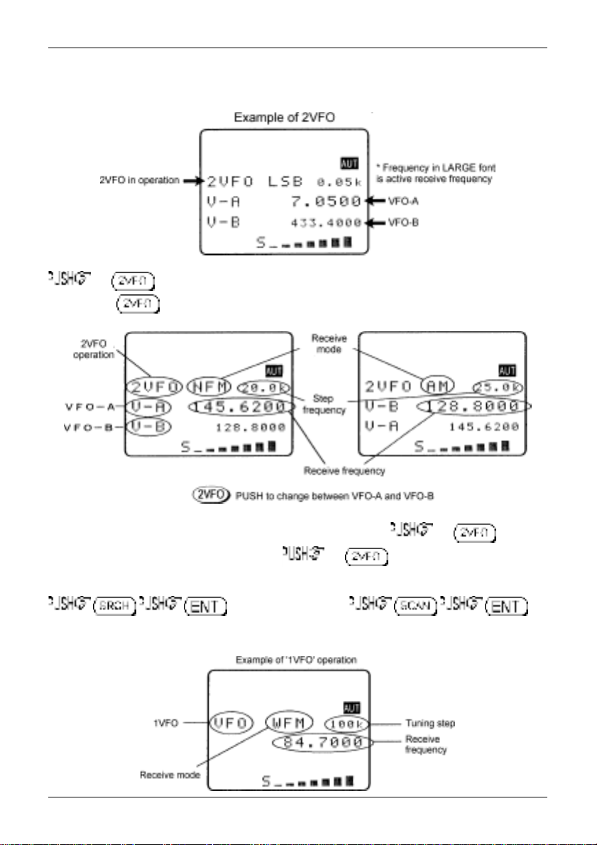
Section 3-2
Both VFO frequencies are displayed in parallel format on the LCD, one above the other. The ‘
VFO (the one which is currently receiving) is displayed using a large font centrally on the LCD, the
‘
standby
’ VFO is shown on a lower line using a smaller font size.
the key to first select ‘
Each time the key is pushed VFO “V-A” and VFO “V-B” alternate between active and standby.
VFO mode
’ (should the receiver be scanning or searching etc).
active
’
The first time you enter a frequency via the numeric keypad, it is best to the key to
place the receiver in a known state of operation. the key so the “V-A” becomes the
active VFO (upper and largest of the two frequency readouts). This condition is referred to as ‘
mode with VFO-A active and VFO-B as standby. If you find the twin frequency display confusing,
or use the key sequence
(while no signal is present) so that only a single frequency readout is displayed, this is referred to as
‘
1VFO
’ mode. Both 1VFO and 2VFO modes may be referred to simply as VFO mode or
2VFO
manual mode
’
.
25
Section 3-2, 3-3
Transfer to active VFO
When the AR8200 has stopped on an active frequency in memory read, scan or search mode, use the
key sequence to transfer the frequency to the active (upper VFO). The
AR8200 will revert to 2VFO mode where the frequency may be monitored.
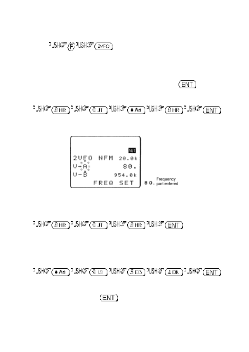
3-3 Entering a frequency using the numeric keypad
While in VFO mode, enter the required frequency using MHz format followed by .
Example of frequency entry 80.8 MHz
There is no need to key in the trailing zeros to the right of the decimal point as they are automatically
added by the microprocessor.
If keying in a whole MHz such as 118.000 MHz there is no need to key in either the decimal point or
trailing zeros, they are all added by the AR8200 microprocessor.
Example of ‘MHz round number’ frequency entry for 808.000 MHz
While keying in frequency data, the bottom line of the LCD displays “FREQ SET” to indicate what sort of
data input the AR8200 is expecting. Similar helpful messages are displayed at other times during data
input.
Example of frequency entry 954 kHz (0.954 MHz)
The frequency of 954 kHz is equivalent to 0.954 MHz. When entering frequencies below 1 MHz, there
is no need to proceed the decimal point with a zero as this is added by the microprocessor during
frequency entry then removed when the key is pushed to ensure the display appears neat
and tidy.
You will note that frequencies below 3.0 MHz (3000 kHz) will be automatically displayed in kiloHertz
format (the letter “k” will be displayed to the right of the frequency readout) and the decimal point
26
Section 3-3, 3-4, 3-5
displayed to the right of the kHz position. This is to ensure easy recognition of short wave frequencies
which are often listed as ‘kHz’ in frequency guides.
If an attempt is made to enter an ‘out of range’ or invalid frequency (such as 2345 MHz or 0.09 MHz) the
error beep will sound (if beep is enabled) and the LCD returns to the previous frequency prior to
frequency input. Acceptable input range is 0.1 MHz to 2040 MHz.
&Note: If you pause during frequency input for more than 90 seconds, the menu will time out
and the AR8200 will return to its previous task just as if the key had been operated.
Aborting frequency input
If for some reason you do not wish to complete the frequency data input, before
completing the input sequence with .
3-4 Correcting frequency input
Should an error be made while entering frequency data (by pressing the wrong numeric key), it may be
corrected using the ð BACKSPACE facility. This facility enables rapid correction of errors prior to the
completion of entry by the enter key.
Example of frequency data correction while keying 433.250 MHz
then
(as if you have made a mistake)
ð, the number “7” clears from the LCD
to finalise the correct entry.
3-5 Changing frequency using the ñ and ò keys
The ñ and ò keys provide a convenient method of frequency change.
The speed at which the receiver steps up or down depends upon the STEP SIZE which is default to
AUTO. In AUTO the step size, receiver mode etc is taken from the factory pre-programmed band plan
but may be overridden at any time.
Examples of tuning step include: 0.05 kHz (50 Hz), 0.1 kHz (100 Hz), 0.2 kHz (200 Hz), 0.5 kHz (500
Hz), 1.00 kHz, 2.00 kHz, 5.00 kHz, 6.25 kHz, 8.33 kHz, 9.00 kHz, 10.00 kHz, 12.50 kHz, 20 kHz, 25.00
kHz, 30 kHz, 50 kHz, 100.00 kHz. The tuning step size may also be programmed in multiples of 50
Hz (via the keypad) so that unusual step sizes other than stated are possible.
the ñ key to tune the receiver upward in whichever step size is selected, use the ò to tune the
receiver downward in frequency. You may and hold either key to continuously tune the
receiver in whichever direction is desired, tuning will stop when the key is released.
27
Section 3-5, 3-6
&Note: In AM and FM
modes with the squelch
open, reception will be
momentarily interrupted
while tuning and the “S”
squelch legend will flash
as tuning progresses, a
‘chuff-chuff’ sound will
accompany tuning, this
is normal.
Fast tuning
The ï and ð keys may be used to tune the receiver at a rate TEN TIMES FASTER than the selected
step size. This means that when a step size of 25 kHz is selected, tuning will be in 250 kHz steps, this
provides a convenient method to quickly tune up and down frequency bands.
&Note: Be aware that when auto-mode is selected and a tuning step change has
automatically taken place, one PUSH up or down may take several pushes to arrive back to
the starting place again.
1 MHz tuning
While the “FUNC” legend is displayed (achieved by a of the key, again to
deactivate as a toggle), the tuning rate for the ñ and ò keys is 1 MHz per increment.
3-6 Changing frequency using the main dial
While in VFO mode, the active VFO frequency may be ‘tuned’ in a similar way to a domestic receiver or
other specialist receivers using the rotary tuning main dial which is mounted on the left hand side of the
cabinet. This is best controlled using the thumb of you left hand (with the set held in your left hand), it
may also be tuned using the middle finger of your right hand or in whatever way you find comfortable.
This method of frequency selection is the most traditional approach to locating signals particularly on
the short wave and medium wave bands. It provides an easy method to locate new or previously
unknown frequencies or to check activity within certain frequency bands such as amateur or short wave
broadcast. The rotary tuning main dial provides the very best ‘user interface’ with the AR8200 especially
for USB, LSB and CW listening.
Rotating the main dial ‘upward’ increases frequency while
rotation ‘downward’ decreases receive frequency.
The speed at which the main dial tunes the receiver depends upon the STEP SIZE which is default to
AUTO. Examples of tuning step include: 0.05 kHz (50 Hz), 0.1 kHz (100 Hz), 0.2 kHz (200 Hz), 0.5 kHz
(500 Hz), 1.00 kHz, 2.00 kHz, 5.00 kHz, 6.25 kHz, 8.33 kHz, 9.00 kHz, 10.00 kHz, 12.50 kHz, 20 kHz,
25.00 kHz, 30 kHz, 50 kHz, 100.00 kHz. The tuning step size may also be programmed in multiples of
50 Hz (via the keypad) so that unusual step sizes other than stated are possible.
While the “FUNC” legend is displayed (achieved by a of the key, again to
deactivate as a toggle), the tuning rate for the main dial is TEN TIMES FASTER than the selected step
size. This means that when a step size of 10 kHz is selected, tuning will be in 100 kHz steps, this
provides a convenient method to quickly tune up and down frequency bands.
28
Section 3-7, 3-7-1, 3-7-2
3-7 Changing receive mode
Due to the necessities of signal bandwidth, channel occupancy and transmission efficiency, different
receive modes are used by various services. In addition to this the specification for tuning step and
receive mode are allocated by departments of Governments following International discussions so are
not consistent throughout the world. For this reason, it is necessary to change receive mode in order to
monitor various transmissions.
For your convenience, receive mode and tuning step size have been pre-programmed into the AR8200
auto-mode bandplan data at the factory to simplify operation of the receiver, especially while you
familiarise yourself with all the facilities. Should you wish, the defaults may be manually over-ridden at
any time so that you may select an alternative receive mode and tuning step on any frequency.
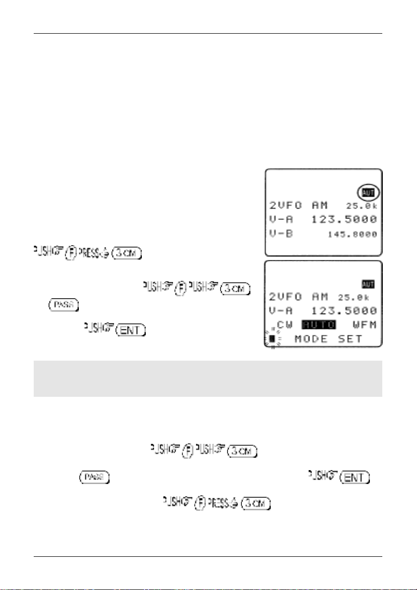
3-7-1 Auto-mode selection
When auto-mode is in operation (so that receive mode and tuning
step size are automatically selected for you by the AR8200
microprocessor), the reverse legend “AUT” is displayed toward the
top right of the LCD.
To activate auto-mode or reconfirm its selection while in VFO mode,
Alternatively “AUTO” may be selected from the “MODE SET” menu
accessed with the key sequence .
The key acts as a short cut to “AUTO”, alternatively use
the main dial or ï ð keys. When the reverse “AUTO” legend has
been selected, to accept the data input. The
LCD will revert to VFO mode with the “AUT” legend confirming
selection.
&Note: Auto-mode is cancelled as soon as the receive mode, tuning step or other
related data is changed. Remember that auto-STEP and auto-MODE are linked, reselect
AUTO-MODE if either have been adjusted and you require the auto bandplan selection.
3-7-2 Receive mode selection menu
Any receive mode may be selected at any frequency within the receiver’s frequency coverage.
To access the receive mode menu , the following modes are available:
AUTO, WFM, NFM, SFM, WAM, AM, SAM, USB, LSB, CW. Use the main dial or ï ð ñ ò keys to make
selection, the key acts as a short cut to “AUTO”. To accept the selection .
As a further short cut to AUTO MODE, . The reverse LCD legend
“AUT” confirms selection.
29

Section 3-7-2
Generally speaking the following modes will apply:
AUTO
Receive mode and tuning step will be selected automatically using the pre-programmed auto
bandplan data.
WFM
Wide band Frequency Modulation - used by VHF and UHF broadcast stations as excellent audio quality
is available due to the relatively wide frequency bandwidth employed. Used only for local services such
as VHF Band-II stereo (received as mono on the AR8200) and UHF TV sound channels.
When listening in VERY strong signal locations especially when using an external aerial, adjacent
channel interference may be observed due to the wide nature of the IF filters. Should interference be
encountered, use the attenuator to reduce signal strength or swap to the standard semi-flexible whip
aerial.
NFM
Narrow band Frequency Modulation - this provides high quality communication for relatively short
distance operation. NFM uses a greater frequency bandwidth than other point-to-point modes such as
SSB so is less efficient.
NFM is the most common mode used above 30 MHz with the exception of the airbands (which use AM).
NFM is widely used on the VHF bands: VHF Marine band, 2m amateur Band (145MHz), 70cm amateur
band (433 MHz), PMR (Private Mobile Radio) and utilities.
In the absence of a signal, the background white noise may appear quite loud. For ease of listening the
squelch control should be rotated clockwise until the background noise just disappears, this should be
carried out when no signal is present. The point where the background noise is cancelled is known as
‘threshold point’. Do not advance the squelch control more than necessary or the receiver will appear to
be desensitised and weaker signals will be missed.
SFM
Super Narrow band Frequency Modulation - this mode is specific to the AR8200. Essentially this is the
same mode as NFM but uses a narrower IF filter for added selectivity when monitoring crowded bands
such as PMR utilities.
WAM
Wide Amplitude Modulation - this mode is specific to the AR8200. It is essentially the same as AM but
uses a wider IF filter, particularly useful for monitoring parasitic airband transmissions when ‘repeater
transmissions’ are employed. Provides good broadcast quality for MW (medium wave band) listening to
strong local signals when adjacent channel transmissions are not encountered.
AM
Amplitude Modulation - Used by broadcast services throughout the world on medium wave and short
wave. AM is also used by VHF civil airband, UHF military airband and some PMR (Private Mobile Radio)
and utility services.
NAM
Narrow Amplitude Modulation - this mode is specific to the AR8200. It is essentially the same as AM but
uses a narrower IF filter for added selectivity when monitoring crowded bands such as short wave. Due
to the narrower bandwidth employed, the audio quality will be compromised.
USB
Upper Side Band - is a form of Single Side Band (SSB). USB is used commercially and by radio
amateurs on frequencies above 10 MHz (below 10 MHz radio amateurs tend to use LSB to assist the
separation of commercial and amateur users on traditionally shared bands, this prevents them from
attempting to communicate with each other… which is prohibited).
30
 Loading...