

Page 1

AOR AR3000A "PLUS" Modifications
Introduction
The following modifications were originally developed by AOR (UK) Ltd as a result of popular requests by
enthusiasts. They are described individually and can be carried out on that basis but when all modifications
are done together they are collectively known as the “AR3000A PLUS” modifications.
The degree of difficulty in carrying out the modifications varies considerably. The discriminator modification
simply involves the addition of one wire whereas the narrow AM filter uses very delicate surface mount
components, fine wiring and the drilling of a hole in the main PCB. We therefore recommend that the instruction are read very carefully and tool kits inspected for suitability before attempting any modification. No test
equipment should be needed for carrying out the modifications but a basic DVM is useful for fault finding. All
modifications can be checked using off air signals and where applicable the SDU5000.
It is assumed before starting a modification that the AR3000 / AR3000A is in full working order and that no
previous modifications have been carried out. All description are based on the fact that the IF board has been
removed from the set; this however is not necessary for some of the simpler modifications and partial removal
is recommended by removing the five coaxial connectors on the front of the board and hinging the board on
it’s remaining wiring loom over the back of the set.
In all the descriptions it is assumed that the front panel is facing towards you and is known as the “front” and
the rear panel away from you and known as the “rear”. Where colour of additional wires is given it is simply
for clarity of description and is based on our original development of the modification. Components described
are again based on those used in our original development and in most cases can be substituted; we have
therefore only given recommended suppliers where the component is of a more specialised nature.
"Limited" support is offered by our technical department, time being valuable!
Written communication is discouraged in respect of these modifications due to the complexity of the
subject matter. For answers to quick questions, phone 01773 880788. AOR (UK) LTD, 4E East Mill,
Bridgefoot, Belper, Derbyshire DE56 2UA. England.
Thank you.
WEFAX SATELLITE narrower switchable filter (1-3000)
The WEFAX custom modification has been designed to optimise the receiver’s passband
for reception of orbital weather satellites operating in the VHF band around 137.500 MHz
and geostationary satellites operating in the UHF band around 1691 MHz. Ideally an IF
bandwidth of 30-50 kHz is required for reasonable results, unmodified the AR3000 /
3000A is too narrow on NFM and too wide on WFM.
A small PCB is mounted on the IF PCB and holds both the original WFM filter for BAND2
& TV sound reception plus a new filter offering approximately 50 kHz bandwidth. The
WFM filters are switched using an IC via a rear panel mounted slide switch (UP is narrow
and DOWN is standard). A small component change is also carried out to ensure the
squelch operates with the bandwidth switch in either position.
Of course you still require some form of data encoder such as the AOR WX2000 decoder/
printer (no longer available as new) or a computer hardware/software package. For VHF
reception a crossed dipole is quite adequate but a dish or yagi is required for UHF along
with a LNA (low noise amplifier). The slide switch may be easily reached from the front of
the set. The bandwidth is of course NOT selectable via computer control.
AOR AR3000/3000A receiver modifications. © AOR (UK) LTD 1994 - 1999 - Page 1
No responsibility is accepted for damage caused by customers carrying out these modifications.
Page 2
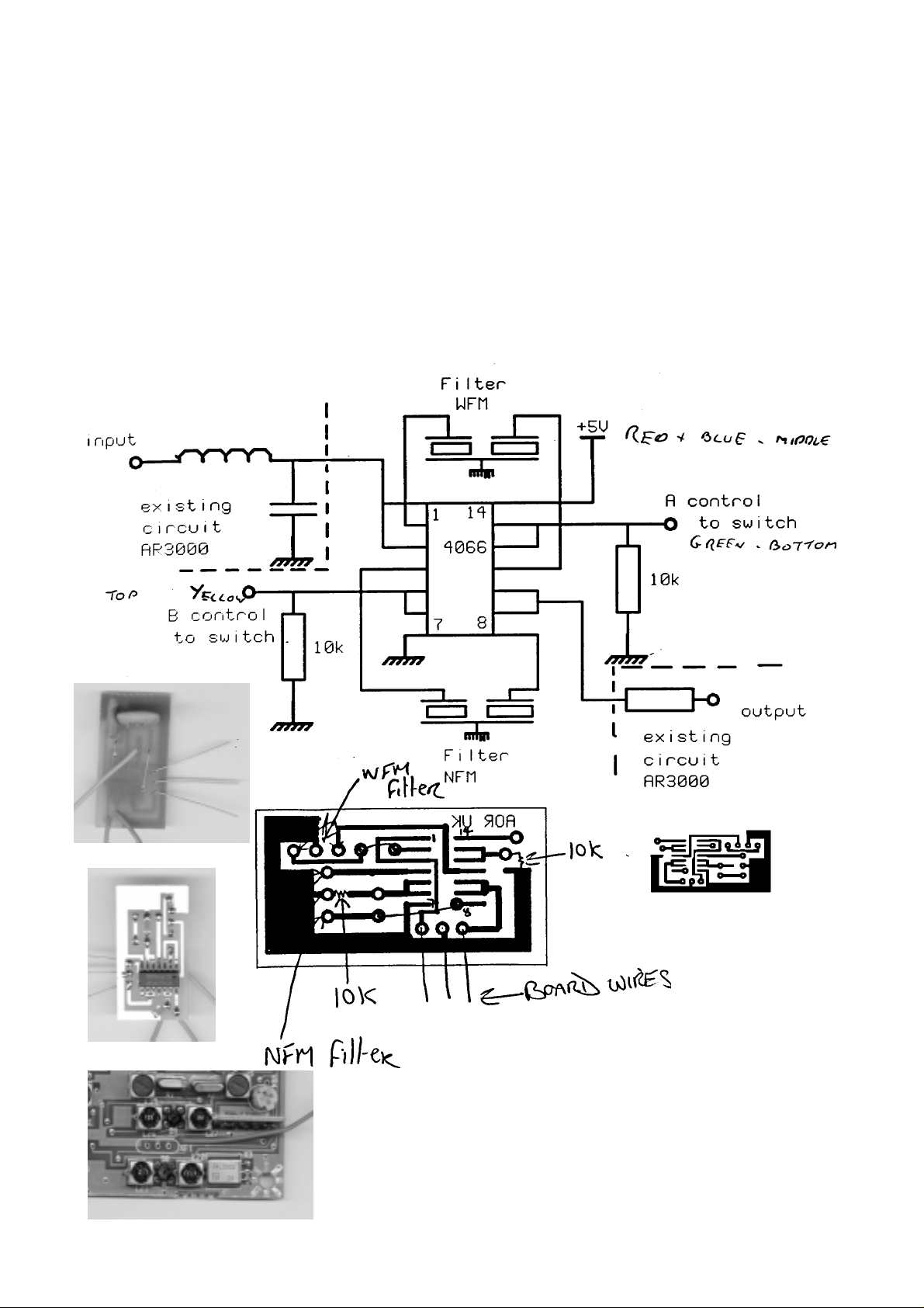
Using the accompanying diagrams and photographs build the small WEFAX PCB, the
parts list being as follows
1 x Blank PCB 30.5 mm x 15.5 mm
1 x SMD 4066 IC quad switch
2 x SMD 10k resistors
1 x Murata SFE 10.7 MF filter, bandwidth 55 kHz Bonex part no 080125
1 x 300 mm green wire
1 x 300 mm blue wire
1 x 300 mm yellow wire
3 x 30 mm tinned wire leads
2 x wire links
WEFAX PCB
"artwork" negati ve
Very carefully remove the existing WFM filter XF1 from the IF
board and solder it to the new WEFAX PCB. Our
experience tells us this is quite a fragile filter.
Add a 30 mm red supply feed wire to the hole in the IF PCB
AOR AR3000/3000A receiver modifications. © AOR (UK) LTD 1994 - 1999 - Page 2
No responsibility is accepted for damage caused by customers carrying out these modifications.
Page 3
alongside the XF1 position (see photograph).
Fit new WEFAX PCB to the IF board where the WFM filter XF1 was removed from.
The board should lean backwards with the filters
towards the rear of the set (see photograph).
Solder the 3 wires to the IF board and the left
hand edge of the new board to L7 transformer
alongside.
Trim and solder the red supply wire to pin 14 of the 4066 IC on the new
WEFAX board.
Locate and remove R57 4k7 resistor from the IF Board (see photograph)
and replace with a 1k0 resistor.
Refit the IF board, twist the blue, yellow and green wires together and run
them down the right hand edge of the IF board with the main loom. Follow the main loom towards the position of the new slide switch.
Using a sharp knife cut out the hole in the rear panel escutcheon next to the antenna
socket to allow the fitting of a miniature DPDT slide switch. Drill out the mounting holes
and fix the switch using 2 x M2x4 screws.
Trim and solder the blue, yellow and green twisted wires to one set of switch contacts
connecting the yellow to the top connection, the blue to the middle connection and the
green to the bottom connection.
The new switch now selects the standard WFM filter in the down position and the new
narrower WEFAX filter in the up position. As a non technical test, tune to a WFM
broadcast signal and switch in the narrower filter. You should hear slightly distorted
reception as the incoming signal is deviated more than the filter bandwidth.
Refit the case halves and the modification is complete.
NARROW AM switchable filter (2-3000)
The narrow AM filter custom modification has been designed to optimise the receiver’s
passband for reception of short wave AM broadcast transmissions. Generally speaking on
long and medium wave a 9 kHz channel spacing is used (in Europe) and a 5 kHz
channel spacing for short wave. The standard AR3000A AM filter is 12 kHz as this
permits reception of “offset” civil airband transmissions, the same filter is also used for
NFM.
The modification adds a rear panel switchable narrow AM filter (the same switch as used
for WEFAX switching - both are switched at the same time if both options are fitted), the
filter specification bandwidth is 4.0 kHz but when fitted “in circuit” is actually wider than
this. There is still a very worthwhile improvement which helps reduce BLOCKING when
listening close-in to a strong transmission, heterodynes may also be reduced or removed
AOR AR3000/3000A receiver modifications. © AOR (UK) LTD 1994 - 1999 - Page 3
No responsibility is accepted for damage caused by customers carrying out these modifications.
Page 4
when listening to many transmissions. There is also a small increase in sensitivity over
the standard filter by a few dB.
The additional narrow AM filter is fitted to the IF PCB with the data lines used to select the
filter by diode switching in conjunction with the rear panel switch. The reception of NFM is
still routed through the standard filter even when the narrow AM filter is selected.
When the narrow AM filter is selected the squelch closing position is affected. Instead of
closing around 11 o’clock, it closes around 2 o’clock. This is not a problem as the
squelch is usually left “open” when monitoring short wave
broadcast transmissions.
The squelch characteristic is normal and unaffected when
in the standard filter position. The bandwidth is of course
NOT selectable via computer control.
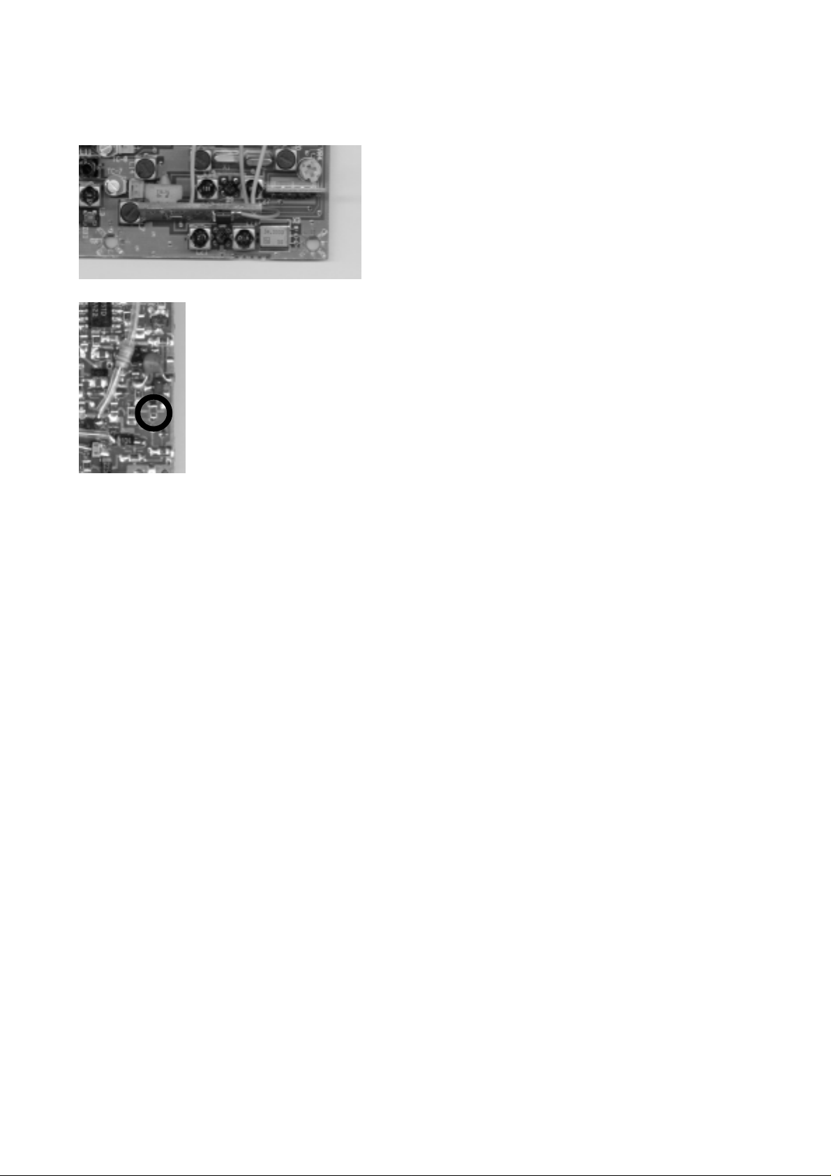
The filter used is a CFW455IT, Bonex part no 080079. The
filter sits on a blob of hot melt between L29 and the existing
AM filter and is prepared in such a way
that of it’s three connections the input
and output legs are extended and pass
through holes in the PCB and the earth
connection sticks out of the side of the
hot melt and solders to the earth plane on
the top side of the board.
Move the grey loop of wire on the underside of the IF board
as far to the right of the PCB as possible and drill a hole 0.8 mm ( through the board next
to L29 on the IF PCB and suck the solder from the second hole if filled (see photograph).
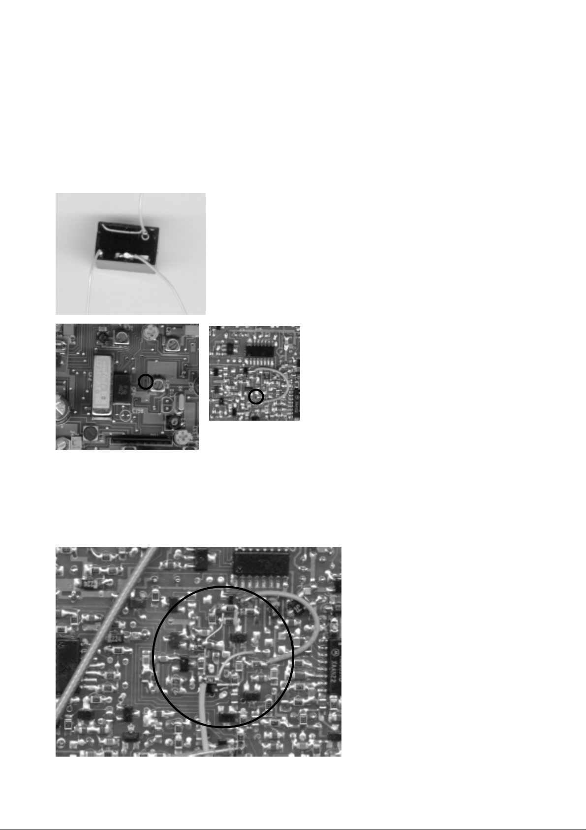
Cut the input and output leg of the filter short and solder a 50 mm length of kynar wire
vertically to each. Cut the middle leg of the three earth connections short and bend and
cut the outer two to meet it. Solder all three together and add a 50 mm kynar earth wire
to exit horizontally to the filter
towards the front of the set. The
overall effect is that the filter
should be able to sit low in it’s
blob of hot melt with its top level
with the muRata SSB filter
CFJ455K, it’s two vertical wires
through the prepared holes and
the earth connection available to
be soldered as close as possible
to the earth land on the top of the
PCB.
On the underside of the board
add 2 x 1SS268 SMD diodes
piggy backed onto 2 existing
AOR AR3000/3000A receiver modifications. © AOR (UK) LTD 1994 - 1999 - Page 4
No responsibility is accepted for damage caused by customers carrying out these modifications.
Page 5
diodes D15 and D17. The 1SS268 is a double diode
package but only one diode in each is used. Solder the front
pins only.
Add a 22k SMD resistor to the front anode of the diode above
D15 and a 5k6 SMD resistor to the rear anode of the diode
above D17
Connect the non diode ends of
the resistors together with a
piece of tinned wire and connect
a 0.01uF SMD capacitor between this tinned wire and an
earth plane (see photograph)
Connect a 300 mm length of yellow wire to aforementioned
tinned wire and connect the kynar wires that are protruding
through the board from the filter to the diode ends of the
resistors, one to each.
Cut track to pin 6 of IC4 and connect a 300 mm blue wire to the now isolated pin.
Connect a 300 mm green wire to the right hand anode of D19.
Insulate the delicate surface mount work with hot melt
Refit the IF board, twist the blue, yellow and green wires together and run them down the
right hand edge of the IF board with the main loom. Follow the main loom towards the
position of the new slide switch.
AOR AR3000/3000A receiver modifications. © AOR (UK) LTD 1994 - 1999 - Page 5
No responsibility is accepted for damage caused by customers carrying out these modifications.
Page 6

Using a sharp knife cut out the hole in the rear panel escutcheon next to the antenna
socket to allow the fitting of a miniature DPDT slide switch. Drill out the mounting holes
and fix the switch using 2 x M2x4 screws.
Trim and solder the blue, yellow and green twisted wires to one set of switch contacts
connecting the yellow to the top connection, the blue to the middle connection and the
green to the bottom connection.
To test the unit tune to a broadcast AM station and switch the narrower filter in. You
should hear a narrowing of tonal quality and a reduction in adjacent channel interference.
Refit the case halves and the modification is complete.
SDU5000 spectrum display compatibility (3-3000)
The SDU5000 is a new spectrum display unit designed to compliment the AR3000A (and
other receivers). In order to provide compatibility, a custom modification has to be carried
out to ensure the AR3000A will plug in and go!
Note: The AR3000 does not provide microprocessor compatibility with the SDU5000 so
only basic facilities are available.
The modification to the AR3000A/3000 adds a rear panel BNC socket providing the
required 10.7 MHz IF signal. The bandwidth is 10 MHz and gain is about 10dB compared
to aerial input. A rear panel toggle switch provides AGC / mute for the SDU, normal is UP
and active is down... the normal position being used most of the time. Of course the
switch is NOT selectable via computer control.
Summary of SDU5000: The SDU5000 Spectrum Display Unit adds a variety of features to
extend a receiver’s capabilities, such as visually identifying new active frequencies and
taking measurements. The SDU5000 may be used with a number of receivers which have
a 10.7 MHz IF output and produces a bandwidth up to ± 5 MHz in 1 kHz increments with a
resolution of 5 kHz or 30 kHz.
The SDU5000 remains compact due to the use of an internal 3.1" HQM simple matrix 16
colour LCD 192 dot x 210 dot. An external home colour television with video input may
also been connected (PAL or NTSC).
In particular the AR3000A has been designed to provide best compatibility by
communicating directly via the receiver’s CPU via the RS232 port / SDU5000 COM1 ensuring the full potential of the SDU may be exploited.
Operation is extremely simple as the SDU5000 utilises an on screen menu system.
The AR3000A frequency, mode & attenuator may be controlled from the SDU so that a
displayed frequency may be easily monitored. When using the AR3000A, the cursor
frequency is equal to the receiving frequency of the AR3000A, by using the cursor in the
SDU, frequency and signal level can be read directly. This enables the SDU5000 to be
used as a wide coverage spectrum monitor between 100 kHz to 2036 MHz with DDS
providing an accuracy of 100ppm. Dynamic range is 50 dB with an acceptable input level
between -10dBm to -90dBm with selectable gain control. The SDU-5000 has a multiple
AOR AR3000/3000A receiver modifications. © AOR (UK) LTD 1994 - 1999 - Page 6
No responsibility is accepted for damage caused by customers carrying out these modifications.
Page 7

processing function which displays Average Level, Peak Detection and Maximum Value
Hold. These professional features are usually only available from expensive professional
class spectrum analysers. The SDU may also be connected to a PC where all controls
are accessible and display data can be downloaded for record and later analysis.
The SDU5000 operates from 12V DC @ 1A and a suitable mains power supply is pro-
vided along with the necessary connecting leads for the AR3000A.
To begin the modification add a 1N40148 diode to the IF board as
shown in the photograph. Connect the cathode to the
cathode of D7 and connect a 300 mm black wire to the anode.
Connect a 470R, 1/8W resistor
between the emitter of Q7 and
the junction of C45 and R29 (see
photograph).
Short the emitter to the collector of Q9 with a small piece of
tinned wire (see photograph).
Add one end of a 1000pF
ceramic capacitor to the junction
of L23 and C48. To the other
end connect the inner of a 250
mm length of miniature 50R
coaxial cable. Connect the braid to the nearest suitable
earth plane.
Insulate all fragile connections with a blob of hot melt and
refit the board making sure that the coaxial lead and the
black single wire exit from under the rear right corner of the board.
Connect a 150 mm red wire to the 9v output of regulator IC11 (right
leg, see photograph) and run towards the back of the board.
Using a sharp knife cut out the rear panel escutcheon below the
antenna socket and file away one of the flats to allow the fitting of a
BNC socket.
Hot melt the coaxial cable along the bottom of the 25 way remote connector and trim and
solder it to the new BNC socket.
Remove the DC socket and find the hole in the rear panel just below the DC socket hole,
puncture the escutcheon and using it as a pilot hole drill a 6.5 mm( hole and fit a miniature
SPDT toggle switch.
Trim and solder the black wire to the middle connection of the switch and trim and solder
the red wire to the top connection of the switch. Refit the DC socket. Check the operation
AOR AR3000/3000A receiver modifications. © AOR (UK) LTD 1994 - 1999 - Page 7
No responsibility is accepted for damage caused by customers carrying out these modifications.
Page 8

of the modification with an SDU5000 or spectrum analyser refit the cases and the
modification is complete.
Tape recorder compatibility (7-3000)
This custom modification enables the AR3000A to provide better compatibility with a range
of “off the shelf” tape recorders. The AR3000A/3000 receiver uses a pair of Darlington
transistors for tape motor On/Off control. While this is suitable for many
machines, some require independent relay contacts.
The modification consists of a small internally fitted double pole slave relay driven by the
switching transistors. One pair of relay contacts feed back to the AUX socket via a 10
OHM resistor (to prevent relay sticking) and provides independent relay contacts not referenced to ground. The second pair of contacts feed audio to the AUX socket when the
squelch is open with a high value resistor preventing noise pick-up when the contact is
open. Constant audio is still fed to another pin of the AUX socket taken from a point before the relay (audio is permanently fed so that commercial users may decode CTCSS
signals without encountering any squelch rise time). This makes the tape output
modification ideally suited for direct DC switching of tape motors (not mains!) and for voice
activated systems.
AUX SOCKET
Pin2: Ground
Pin4: Constant audio out
Pin5: Squelch operated audio output for VOX
Pin6: Relay switch contact
Pin7: Relay switch contact
A standard tape lead CR400 is available as an option terminating in 3.5 mm mono plugs
for audio and a 2.5 mm plug for tape motor control.
Begin the modification by removing the DC socket and aux socket.
Remove the brown and white wires from pins 6 and 7 of the aux socket and connect the
white wire to a +ve 12v supply on the rear of the power socket or pin 3 of the aux socket if
available (this was not fitted on earlier models)
Remove the 220k resistor from pins 4 and 5 and connect a 100k resistor from pin 5 to pin
2 (gnd)
Connect a pair of 100 mm blue wires to pins 6 and 7 and a pair of 100 mm yellow wires to
pin 4 and 5.
Refit the aux socket and DC socket
Using a 12v double pole relay with internal diode protection trim and solder the pair of blue
wires to one pair of normally open contacts. Fit a 10( 1/8W resistor in series to prevent the
relay contacts sticking.
AOR AR3000/3000A receiver modifications. © AOR (UK) LTD 1994 - 1999 - Page 8
No responsibility is accepted for damage caused by customers carrying out these modifications.
Page 9

Trim and solder the yellow pair of wires to the second pair of normally open contacts on
the relay.
Connect the brown wire removed from the aux socket to the +ve coil connection on the
relay and connect a black wire between the -ve connection and an earth connection
(remote socket PCB)
Stick the relay to the inside of the rear panel, check operation of the switching and refit the
case halves. That completes the modification.
Discriminator output (9-3000)
This custom modification provides an output to the rear panel AUX socket taken directly
from the FM MC3357 IC. This ensures the best compatibility with specialist data receives
used on the VHF bands for decoding pagers etc.
AUX SOCKET
Pin2: Ground
Pin1: Discriminator output
On the underside of the IF PCB solder a 300 mm black wire to pin
9 of IC! (see photograph) and refit the board.
Remove the DC socket and aux socket. Connect the black wire to
pin 1 of the aux socket and refit both sockets. Test the operation
and refit the case halves. That completes the modification.
AOR AR3000/3000A receiver modifications. © AOR (UK) LTD 1994 - 1999 - Page 9
No responsibility is accepted for damage caused by customers carrying out these modifications.
Page 10

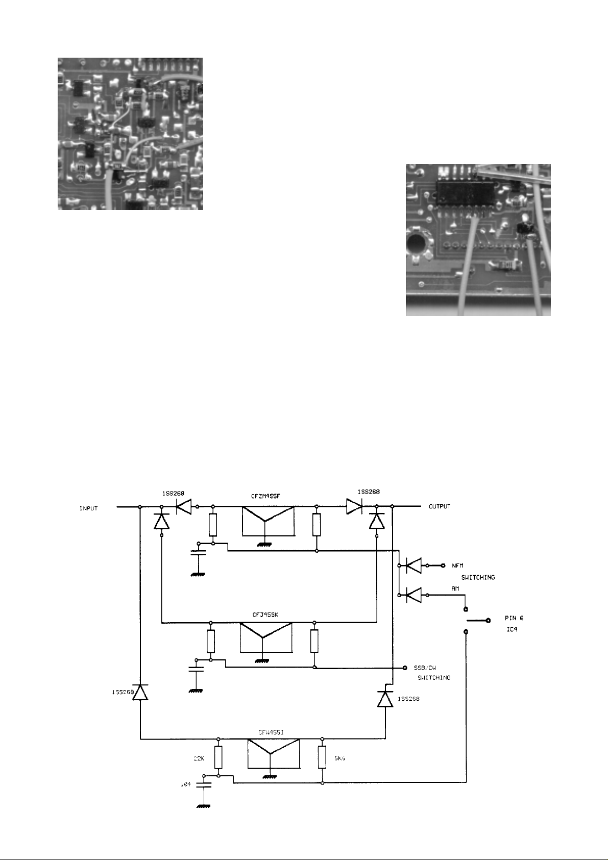
Unmodified I.F. PCBs
AOR AR3000/3000A receiver modifications. © AOR (UK) LTD 1994 - 1999 - Page 10
No responsibility is accepted for damage caused by customers carrying out these modifications.
Page 11

AOR AR3000/3000A receiver modifications. © AOR (UK) LTD 1994 - 1999 - Page 11
No responsibility is accepted for damage caused by customers carrying out these modifications.
Page 12

AOR AR3000/3000A receiver modifications. © AOR (UK) LTD 1994 - 1999 - Page 12
No responsibility is accepted for damage caused by customers carrying out these modifications.
Page 13

AOR AR3000/3000A receiver modifications. © AOR (UK) LTD 1994 - 1999 - Page 13
No responsibility is accepted for damage caused by customers carrying out these modifications.
Page 14

AOR AR3000/3000A receiver modifications. © AOR (UK) LTD 1994 - 1999 - Page 14
No responsibility is accepted for damage caused by customers carrying out these modifications.
Page 15

AOR AR3000/3000A receiver modifications. © AOR (UK) LTD 1994 - 1999 - Page 15
No responsibility is accepted for damage caused by customers carrying out these modifications.
Page 16

AOR AR3000/3000A receiver modifications. © AOR (UK) LTD 1994 - 1999 - Page 16
No responsibility is accepted for damage caused by customers carrying out these modifications.
Page 17

AOR AR3000/3000A receiver modifications. © AOR (UK) LTD 1994 - 1999 - Page 17
No responsibility is accepted for damage caused by customers carrying out these modifications.
Page 18

Price list for customising existing AR3000A & AR3000 receivers
Full details of custom modifications are available in a separate sales booklet. If you select only a single
modification from any group then the higher price is applied as the cases and PCBs need to be removed just for one job,
savings can be made if several modifications are carried out at the same time. Prices £ Pound Sterling E&OE.
Group A
If more than one group "A" modification is selected then the lower price is applied to each modification as the unit will
already have been stripped making work more cost effective.
Group B
There is no lower price available for group "B" as work is time consuming.
Group C
If either a group "A" or group "B" modification is selected then the lower price is applied to group "C" modifications as the
unit is already stripped making work cost effective.
Group A (lower price applies if more than one group A modification is carried out)
1-3000 WEFAX switched WFM filter £39.95 inc VAT / 34.95
2-3000 Narrow AM switched filter £39.95 inc VAT / 34.95
3-3000 SDU 10.7 MHz IF & switch £39.95 inc VAT / 34.95
4-3000 10.7 MHz I.F. only £35.95 inc VAT / 32.95
5-3000 45 MHz I.F. for commercial use £39.95 inc VAT / 34.95
Group B (no lower price available)
6-3000 S-meter output £19.95 inc VAT /
7-3000 Tape recorder switching £19.95 inc VAT /
Group C (lower price applies if a group A or B modification is also carried out)
8-3000 Microprocessor reset switch £14.95 inc VAT / 9.95
9-3000 Discriminator output for decoder £14.95 inc VAT / 4.95
10-3000 Encoder change for AR3000A only £19.95 inc VAT / 14.95
11-3000 RS232 switch for AR3000 only £19.95 inc VAT / 14.95
Carriage on modified units
Return carriage using insured courier Parcel Force PF24 (next working day) is typically £10.00 inc VAT. We are also able
to collect your receiver from your home or place of work using our PF24 courier facility. Pack the parcel well in a carton
box, write our name & address clearly on the outside of the carton and give us a call... we will arrange the rest. The
charge is £22.00 for the round trip.
Many other accessories and custom made leads are available for the AR3000A/3000 (leads are hand made), please
phone for a quote.
*** It is unlikely that we will be able to offer the modification service on a while you wait basis, the work should
usually be carried out within one working week. Please feel free however to phone and discuss fitting in our
workshop.
If you are currently looking for a custom modified AR3000A then the
AR3000A PLUS
will save money compared to the lowest tariff charges - please see overleaf.
Perhaps now is the time to consider upgrading your current equipment.
AOR AR3000/3000A receiver modifications. © AOR (UK) LTD 1994 - 1999 - Page 18
No responsibility is accepted for damage caused by customers carrying out these modifications.
Page 19

Customised AR3000A receiver
Distributed by AOR (UK) L TD
The
AR3000A+ (PLUS)
several custom modifications which have been developed and implemented in our UK
workshop. A summary of the additions and operation follows
WEFAX SATELLITE narrower switchable filter
The WEFAX custom modification has been designed to optimise the receiver’s
passband for reception of orbital weather satellites operating in the VHF band around
137.500 MHz and geostationary satellites operating in the UHF band around 1691 MHz.
Ideally an I.F. bandwidth of 30 - 50 kHz is required for reasonable results, unmodified
the AR3000A is too narrow on NFM and too wide on WFM.
Of course you still require some form of data decoder such as the AOR WX2000
decoder/printer (no longer available as new) or a computer hardware / software
package. For VHF reception a crossed dipole is quite adequate but a dish or yagi is
required for UHF along with a LNA (low noise amplifier).
NARROW AM switchable filter
The narrow AM filter custom has been designed to optimise the receiver’s passband for
reception of short wave AM broadcast transmissions. Generally speaking on long and
medium wave a 9 kHz channel spacing is used (in Europe) and a 5 kHz channel
spacing for short wave. The standard AR3000A AM filter is 12 kHz as this permits
reception of “offset” civil airband transmissions, the same filter is also used for NFM.
The modification adds a rear panel switchable narrow AM filter (the same switch
as used for WEFAX switching - both are switched at the same time), the filter
specification bandwidth is 4.0 kHz but when fitted “in circuit” is actually wider than this.
There is still a very worthwhile improvement which helps reduce BLOCKING when
listening close to a strong transmission, heterodynes may also be reduced or removed
when listening to many transmissions. There is also a small increase in sensitivity over
the standard filter by a few dB.
is the result of popular request by enthusiasts and carries
:
SDU5000 spectrum display "ready"
A new spectrum display unit designed to compliment the AR3000A, in order to provide compatibility, a
custom modification has to be carried out to ensure the AR3000A+
Summary of SDU5000: The SDU-5000 Spectrum Display Unit adds a variety of features to extend a receiver’s capabilities, such
as visually identifying new active frequencies and taking measurements. The SDU-5000 may be used with a number of receivers
which have a 10.7 MHz I.F. output and produces a bandwidth up to ± 5 MHz in 1 kHz increments with a resolution of 5 kHz or 30
kHz. The SDU-5000 remains compact due to the use of an internal 3.1" HQM simple matrix 16 colour LCD 192 dot x 210 dot.
An external home colour television with video input may also been connected (PAL or NTSC). In particular the AR3000A has been
designed to provide best compatibility by communicating directly via the receiver’s CPU via the RS232 port / SDU-5000 COM1
ensuring the full potential of the SDU may be exploited.
(PLUS)
is ready to go!
Tape recorder compatibility
This custom modification enables the AR3000A to provide better compatibility with a range of off the shelf tape recorders. The
receiver uses a pair of Darlington transistors for tape motor On/Off control. While this is suitable for many machines, some require
independent relay contacts.
The modification consists of a small internally fitted double pole slave relay driven by the switching transistors. One pair of relay
contacts feed back to the AUX socket via a 10 OHM resistor (to prevent relay sticking) and provides independent relay contacts not
referenced to ground. The second pair of contacts feed audio to the AUX socket when the squelch is open with a high value resistor
preventing noise pick-up when the contact is open. Constant audio is still fed to another pin of the AUX socket taken from a point
before the relay (audio is permanently fed so that commercial users may decode CTCSS signals without encountering any squelch
rise time). This makes the tape output modification ideally suited for direct DC switching of tape motors (not mains!) and for voice
activated systems.
Discriminator output
This custom modification provides an output to the rear panel AUX socket taken directly from the FM MC3357 IC. This ensures the
best compatibility with specialist data receives used on the VHF bands for decoding pagers etc.
AR3000A PLUS
AOR AR3000/3000A receiver modifications. © AOR (UK) LTD 1994 - 1999 - Page 19
No responsibility is accepted for damage caused by customers carrying out these modifications.
now available to order, please call for current price.
 Loading...