

Page 1
Page 2

Page 3
IMPORTANT SAFETY INSTRUCTIONS
CAUTION
RISK OF ELECTRIC SHOCK
DO NOT OPEN
CAUTION: TO REDUCE THE RISK OF ELECTRIC
SHOCK, DO NOT REMOVE COVER (OR BACK). NO
USER-SERVICEABLE PARTS INSIDE. REFER
SERVICING TO QUALIFIED SERVICE PERSONNEL.
The lightning flash with arrowhead symbol within an equilateral
triangle is intended to alert the user to the presence of uninsulated
“dangerous voltage” within the product’s enclosure that may be of
sufficient magnitude to constitute a risk of electric shock to persons.
The exclamation point within an equilateral triangle is intended to alert
the user to the presence of important operating and maintenance
(servicing) instructions in the literature accompanying the appliance.
1. Read these instructions.
2. Keep these instructions.
3. Heed all warnings.
4. Follow all instructions.
5. Do not use this apparatus near water.
6. Clean only with a dry cloth.
7. Do not block any of the ventilation openings. Install in accordance with the manufacturer’s instructions.
8. Do not install near any heat sources such as radiators, heat registers, stoves or other apparatus (including amplifiers)
that produce heat.
9. Do not defeat the safety purpose of the polarized or grounding-type plug. A polarized plug has two blades with one
wider than the other. A grounding-type plug has two blades and a third grounding prong. The wide blade or the third
prong is provided for your safety. When the provided plug does not fit into your outlet, consult an electrician for
replacement of the obsolete outlet.
10. Protect the power cord from being walked on or pinched, particularly at plugs, convenience receptacles and the point
where they exit from the apparatus.
11. Only use the attachments/accessories specified by the manufacturer.
12. Use only with a cart, stand, tripod, bracket or table specified by the manufacturer, or sold with the
apparatus. When a cart is used, use caution when moving the cart/apparatus combination to avoid injury
from tip-over.
13. Unplug this apparatus during lightning storms or when unused for long periods of time.
14. Refer all servicing to qualified service personnel. Servicing is required when the apparatus has been damaged in any
way, such as power supply cord or plug is damaged, liquid has been spilled or objects have fallen into the apparatus,
the apparatus has been exposed to rain or moisture, does not operate normally, or has been dropped.
Page 4

WARNING: To reduce the risk of fire or electric shock, do not expose this apparatus to rain or moisture. Avoid installing
this unit where foreign objects may fall onto this unit and/or this unit may be exposed to liquid dripping or splashing. On
the top of this unit, do not place:
• Burning objects (i.e. candles), as they may cause fire, damage to this unit, and/or personal injury.
• Containers with liquid in them, as they may fall and liquid may cause electrical shock to the user and/or damage to
this unit.
Apparatus shall not be exposed to dripping or splashing and no objects filled with liquids, such as vases, shall be placed
on the apparatus.
Do not install this equipment in a confined space such as a case or similar. Install it away from direct sunlight, heat
sources, vibration, dust, moisture, and/or cold.
Do not cover this unit with a newspaper, tablecloth, curtain, etc. in order not to obstruct heat radiation. If the temperature
inside this unit rises, it may cause fire, damage to this unit, and/or personal injury.
Install this unit near the AC outlet and where the AC power plug can be reached easily.
This unit is not disconnected from the AC power source as long as the Main Power Switch on the rear panel is ON. This
state is called the standby mode. In this state, this unit is designed to consume a very small quantity of power.
NOTE: This product is not an auto voltage Receiver. Connect only to the prescribed AC outlet, i.e., 120V 60Hz or 230V 50Hz.
CAUTION: These servicing instructions are for use by qualified service personnel only. To reduce the risk of electric shock,
do not perform any servicing other than that contained in the operating instructions, unless you are qualified to do so.
CAUTION: Changes or modifications to this equipment not expressly approved by Paradigm Electronics for compliance
could void the user’s authority to operate this equipment.
FCC WARNING: Changes or modifications not expressly approved by the party responsible for compliance could void the
user’s authority to operate the equipment.
This equipment has been tested and found to comply with the limits for a class B digital device, pursuant to part 15 of the
FCC Rules. These limits are designed to provide reasonable protection against harmful interference in a residential
installation. This equipment generates, uses and can radiate radio frequency energy and, if not installed and used in
accordance with the instructions, may cause harmful interference to radio communications. However, there is no
guarantee that interference will not occur in a particular installation. If this equipment does cause harmful interference to
radio or television reception, which can be determined by turning the equipment off and on, the user is encouraged to try
to correct the interference by one or more of the following measures:
• Reorient or relocate the receiving antenna.
• Increase the separation between the equipment and receiver.
• Connect the equipment into an outlet on a circuit different from that to which the receiver is connected.
• Consult the dealer or an experienced radio / TV technician for help.
DO NOT LOCATE IN THE FOLLOWING PLACES:
To ensure long-lasting use, do not locate the unit:
• Exposed to direct sunlight.
• Near sources of heat such as heaters.
• Highly humid or poorly ventilated.
• Dusty.
• Subjected to mechanical vibrations.
• On wobbly, inclined, or otherwise unstable surfaces.
• Near windows where there is a chance of exposure to rain,
etc.
• On top of an amplifier or other component which dissipates a
great deal of heat.
To ensure proper heat radiation ensure clearance from walls
and other equipment according to diagram.
Left 0.2 m (8 in)
or more
Above 0.2 m
(8 in) or more
Behind 0.2 m (8 in) or more
Right 0.2 m
(8 in) or more
Page 5
IMPORTANT INFORMATION FOR UK CUSTOMERS: DO NOT cut off the mains plug from this equipment. If the plug fitted is
not suitable for the power points in your home or the cable is too short to reach a power point, then obtain an appropriate
safety approved extension lead or consult your dealer. If, nonetheless, the mains plug is cut off, REMOVE THE FUSE and
dispose of the PLUG immediately, to avoid possible shock hazard by inadvertent connection to the mains supply. If this
product is not provided with a mains plug, or one has to be fitted, then follow the instructions given below:
IMPORTANT: DO NOT make any connection to the larger terminal which is marked with the letter “E” or by the safety
earth symbol or colored GREEN or GREEN AND YELLOW.
The wires in the mains lead on this product are colored in accordance with the following code:
BLUE – NEUTRAL
BROWN – LIVE
As these colors may not correspond with the colored markings identifying the terminals in your plug, proceed as follows:
The BLUE wire must be connected to the terminal marked with the letter “N” or colored BLACK.
The BROWN wire must be connected to the terminal marked with the letter “L” or colored RED.
When replacing the fuse, only a correctly rated and approved type should be used, and be sure to re-fit the fuse cover.
If in doubt consult a competent electrician.
Page 6

NOTES ON ENVIRONMENTAL PROTECTION
At the end of its useful life, this product must not be disposed of with regular household waste but must be returned to a
collection point for the recycling of electrical and electronic equipment. The symbol on the product, user’s manual and
packaging, point this out. The materials can be reused in accordance with their markings. Through re-use, recycling of
raw materials or other forms of recycling of old products, you are making an important contribution to the protection of
our environment. Your local administrative office can advise you of the responsible waste disposal point.
INFORMATION ABOUT COLLECTION AND DISPOSAL OF WASTE BATTERIES (DIRECTIVE 2006/66/EC OF THE EUROPEAN
PARLIAMENT AND THE COUNCIL OF EUROPEAN UNION) (for European customers only)
Batteries bearing any of these symbols indicate that they should be treated as “separate collection” and not as municipal
waste. It is encouraged that necessary measures are implemented to maximize the separate collection of waste batteries
and to minimize the disposal of batteries as mixed municipal waste. End-users are exhorted not to dispose waste batteries
as unsorted municipal waste. In order to achieve a high level of recycling waste batteries, discard waste batteries
separately and properly through an accessible collection point in your vicinity. For more information about collection and
recycling of waste batteries, please contact your local municipality, your waste disposal service or the point of sale where
you purchased the items.
By ensuring compliance and conformance to proper disposal of waste batteries, potential hazardous effects on human
health is prevented and the negative impact of batteries and waste batteries on the environment is minimized, thus
contributing to the protection, preservation and quality improvement of the environment.
Pb Hg Cd
Anthem and any related party assume no liability for the user’s failure to comply with any requirements.
Anthem, AnthemLogic, ARC, Sonic Frontiers, and Paradigm are trademarks or registered trademarks of Paradigm Electronics Inc.
Copyright Paradigm Electronics Inc. All rights reserved. The information contained herein may not be reproduced in whole or in part
without our express written permission. We reserve the right to change specifications and/or features without notice as design
Manufactured under license from Dolby Laboratories. Dolby, Pro Logic, and
the double-D symbol are trademarks of Dolby Laboratories.
Manufactured under license under U.S. Patent #’s: 5,451,942; 5,956,674; 5,974,380; 5,978,762; 6,226,616; 6,487,535; 7,212,872; 7,333,929;
7,392,195; 7,272,567 & other U.S. and worldwide patents issued & pending. DTS and the Symbol are registered trademarks, & DTS-HD,
DTS-HD Master Audio, and the DTS logos are trademarks of DTS, Inc. Product includes software. © DTS, Inc. All Rights Reserved.
This item incorporates copy protection technology that is protected by U.S. patents and other intellectual property rights of
Rovi Corporation. Reverse engineering and disassembly are prohibited.
HDMI, the HDMI logo and High-Definition Multimedia Interface are trademarks or registered trademarks of HDMI Licensing LLC.
iPhone and iPod are registered trademarks of Apple Inc., registered in the U.S. and other countries.
(MRX 700 US model only) HD Radio™ Technology Manufactured under license from iBiquity Digital Corp. U.S.
and Foreign Patents. HD Radio™ and the HD Radio logo are proprietary trademarks of iBiquity Digital Corp.
improvements are incorporated.
All other trademarks are the property of their respective owners.
Page 7

TABLE of CONTENTS
SECTION PAGE
1. INTRODUCTION
1.1 Before Making Connections. . . . . . . . . . . . . . . . . . . . . . . . . . . . . . . . . . . . . . . . . . . . . . . . . . . . . . . . . . . . . 1
1.2 In-Use Notices . . . . . . . . . . . . . . . . . . . . . . . . . . . . . . . . . . . . . . . . . . . . . . . . . . . . . . . . . . . . . . . . . . . . . . . . 1
1.3 Front Panel . . . . . . . . . . . . . . . . . . . . . . . . . . . . . . . . . . . . . . . . . . . . . . . . . . . . . . . . . . . . . . . . . . . . . . . . . . . . 2
1.4 Front Panel Display . . . . . . . . . . . . . . . . . . . . . . . . . . . . . . . . . . . . . . . . . . . . . . . . . . . . . . . . . . . . . . . . . . . . . 3
1.5 Rear Panel . . . . . . . . . . . . . . . . . . . . . . . . . . . . . . . . . . . . . . . . . . . . . . . . . . . . . . . . . . . . . . . . . . . . . . . . . . . . 4
1.6 Remote Controls . . . . . . . . . . . . . . . . . . . . . . . . . . . . . . . . . . . . . . . . . . . . . . . . . . . . . . . . . . . . . . . . . . . . . . . 5
1.7 Speaker Placement . . . . . . . . . . . . . . . . . . . . . . . . . . . . . . . . . . . . . . . . . . . . . . . . . . . . . . . . . . . . . . . . . . . . . 6
2. CONNECTIONS
2.1 Video . . . . . . . . . . . . . . . . . . . . . . . . . . . . . . . . . . . . . . . . . . . . . . . . . . . . . . . . . . . . . . . . . . . . . . . . . . . . . . . . . 7
2.2 Audio . . . . . . . . . . . . . . . . . . . . . . . . . . . . . . . . . . . . . . . . . . . . . . . . . . . . . . . . . . . . . . . . . . . . . . . . . . . . . . . . . 8
2.3 Antennas . . . . . . . . . . . . . . . . . . . . . . . . . . . . . . . . . . . . . . . . . . . . . . . . . . . . . . . . . . . . . . . . . . . . . . . . . . . . . . 8
2.4 Ethernet . . . . . . . . . . . . . . . . . . . . . . . . . . . . . . . . . . . . . . . . . . . . . . . . . . . . . . . . . . . . . . . . . . . . . . . . . . . . . . . 9
3. SETUP
2.5 MDX 1 Dock (optional). . . . . . . . . . . . . . . . . . . . . . . . . . . . . . . . . . . . . . . . . . . . . . . . . . . . . . . . . . . . . . . . . . 9
2.6 12V Trigger . . . . . . . . . . . . . . . . . . . . . . . . . . . . . . . . . . . . . . . . . . . . . . . . . . . . . . . . . . . . . . . . . . . . . . . . . . . . 9
2.7 Infra Red Input . . . . . . . . . . . . . . . . . . . . . . . . . . . . . . . . . . . . . . . . . . . . . . . . . . . . . . . . . . . . . . . . . . . . . . . . . 9
2.8 Infra Red Output . . . . . . . . . . . . . . . . . . . . . . . . . . . . . . . . . . . . . . . . . . . . . . . . . . . . . . . . . . . . . . . . . . . . . . . . 9
2.9 Switched AC Outlet. . . . . . . . . . . . . . . . . . . . . . . . . . . . . . . . . . . . . . . . . . . . . . . . . . . . . . . . . . . . . . . . . . . . . 9
2.10 Power . . . . . . . . . . . . . . . . . . . . . . . . . . . . . . . . . . . . . . . . . . . . . . . . . . . . . . . . . . . . . . . . . . . . . . . . . . . . . . . . . 9
Navigating in the Setup Menu. . . . . . . . . . . . . . . . . . . . . . . . . . . . . . . . . . . . . . . . . . . . . . . . . . . . . . . . . . . . . . . 13
Quick Setup . . . . . . . . . . . . . . . . . . . . . . . . . . . . . . . . . . . . . . . . . . . . . . . . . . . . . . . . . . . . . . . . . . . . . . . . . . . . . . . 14
3.1 Video Output Configuration . . . . . . . . . . . . . . . . . . . . . . . . . . . . . . . . . . . . . . . . . . . . . . . . . . . . . . . . . . . . 14
3.2 Speaker Configuration. . . . . . . . . . . . . . . . . . . . . . . . . . . . . . . . . . . . . . . . . . . . . . . . . . . . . . . . . . . . . . . . . 15
3.3 Listener Position . . . . . . . . . . . . . . . . . . . . . . . . . . . . . . . . . . . . . . . . . . . . . . . . . . . . . . . . . . . . . . . . . . . . . . 16
3.4 Level Calibration . . . . . . . . . . . . . . . . . . . . . . . . . . . . . . . . . . . . . . . . . . . . . . . . . . . . . . . . . . . . . . . . . . . . . 17
3.5 Source Setup . . . . . . . . . . . . . . . . . . . . . . . . . . . . . . . . . . . . . . . . . . . . . . . . . . . . . . . . . . . . . . . . . . . . . . . . . 19
3.6 Listening Mode Presets. . . . . . . . . . . . . . . . . . . . . . . . . . . . . . . . . . . . . . . . . . . . . . . . . . . . . . . . . . . . . . . . 21
3.7 Video Mode Presets . . . . . . . . . . . . . . . . . . . . . . . . . . . . . . . . . . . . . . . . . . . . . . . . . . . . . . . . . . . . . . . . . . . 22
3.8 Displays and Timeout. . . . . . . . . . . . . . . . . . . . . . . . . . . . . . . . . . . . . . . . . . . . . . . . . . . . . . . . . . . . . . . . . . 23
3.9 Trigger Configuration. . . . . . . . . . . . . . . . . . . . . . . . . . . . . . . . . . . . . . . . . . . . . . . . . . . . . . . . . . . . . . . . . . 24
3.10 General Configuration . . . . . . . . . . . . . . . . . . . . . . . . . . . . . . . . . . . . . . . . . . . . . . . . . . . . . . . . . . . . . . . . . 25
3.11 Anthem Room Correction (ARC) . . . . . . . . . . . . . . . . . . . . . . . . . . . . . . . . . . . . . . . . . . . . . . . . . . . . . . . . 26
3.12 Multimedia . . . . . . . . . . . . . . . . . . . . . . . . . . . . . . . . . . . . . . . . . . . . . . . . . . . . . . . . . . . . . . . . . . . . . . . . . . . 30
Page 8

4. OPERATION
4.1 Power On and Off . . . . . . . . . . . . . . . . . . . . . . . . . . . . . . . . . . . . . . . . . . . . . . . . . . . . . . . . . . . . . . . . . . . . . 31
4.2 Zone Selection . . . . . . . . . . . . . . . . . . . . . . . . . . . . . . . . . . . . . . . . . . . . . . . . . . . . . . . . . . . . . . . . . . . . . . . 31
4.3 Source Selection . . . . . . . . . . . . . . . . . . . . . . . . . . . . . . . . . . . . . . . . . . . . . . . . . . . . . . . . . . . . . . . . . . . . . 31
4.3.1 Tuner 32
4.3.2 Multimedia 32
4.4 Level Trim . . . . . . . . . . . . . . . . . . . . . . . . . . . . . . . . . . . . . . . . . . . . . . . . . . . . . . . . . . . . . . . . . . . . . . . . . . . 33
4.5 Audio Adjustments . . . . . . . . . . . . . . . . . . . . . . . . . . . . . . . . . . . . . . . . . . . . . . . . . . . . . . . . . . . . . . . . . . . 33
4.6 Listening Modes . . . . . . . . . . . . . . . . . . . . . . . . . . . . . . . . . . . . . . . . . . . . . . . . . . . . . . . . . . . . . . . . . . . . . . 33
4.6.1 AnthemLogic 34
4.6.2 Dolby Digital 2.0 35
4.6.3 Surround Modes for 2.0-Channel Sources 35
4.6.4 Dolby Virtual Speaker 35
4.6.5 Dolby Digital 36
4.6.6 DTS 36
4.6.7 Dolby Volume and Dynamic Range Control 37
4.7 Resolution . . . . . . . . . . . . . . . . . . . . . . . . . . . . . . . . . . . . . . . . . . . . . . . . . . . . . . . . . . . . . . . . . . . . . . . . . . . 37
4.8 Display Brightness . . . . . . . . . . . . . . . . . . . . . . . . . . . . . . . . . . . . . . . . . . . . . . . . . . . . . . . . . . . . . . . . . . . 37
4.9 Sleep Timer . . . . . . . . . . . . . . . . . . . . . . . . . . . . . . . . . . . . . . . . . . . . . . . . . . . . . . . . . . . . . . . . . . . . . . . . . . . 37
4.10 Info Display . . . . . . . . . . . . . . . . . . . . . . . . . . . . . . . . . . . . . . . . . . . . . . . . . . . . . . . . . . . . . . . . . . . . . . . . . . 38
4.11 Software Upgrade – Multimedia Section (not available on MRX 300) . . . . . . . . . . . . . . . . . . . . . . . . 38
4.12 Software Upgrade – Main Section. . . . . . . . . . . . . . . . . . . . . . . . . . . . . . . . . . . . . . . . . . . . . . . . . . . . . . . 38
Specifications 39
Limited Warranty 41
Big Pictures of Front and Rear Panels Inside Back Cover
Page 9

1. INTRODUCTION
Thank you for purchasing the Anthem MRX series receiver.
The MRX 300, MRX 500, and MRX 700 receivers are cutting-edge home theater audio components with HDMI
switching and video upconversion, multimedia and second zone capabilities, FM/AM tuner, HD Radio™
reception (MRX 700 120V model) and connection for optional MDX 1 iPod / iPhone dock.
Anthem products are engineered to recreate the passion of live performance and thrill of the best movie
theaters by using the highest level of circuit design, proprietary software, superior build quality, innovative
features, and intuitive ergonomics with tremendous flexibility.
1.1 BEFORE MAKING CONNECTIONS
Check that you have received everything listed below and report discrepancies to your dealer as soon as
possible. In case they are needed one day, keep the packing materials and the invoice that you received from
your authorized Anthem dealer at time of purchase – without it, service will not be provided under warranty.
Packing List:
• MRX Receiver • FM antenna • Zone 2 remote control
• Main remote control • AM loop antenna • CR2025 battery
• 2 AAA batteries • IEC power cord (US or EU type only)
Additional items with Anthem Room Correction (ARC):
• Software installation CD • Microphone and clip • Telescopic stand
• Serial extension cable • USB microphone cable
Serial Number:
• While it’s accessible, record it here for future reference
1.2 IN-USE NOTICES
• Disconnect the power cord before connecting or disconnecting any components.
• If the receiver was transported or stored in the cold, let it warm to room temperature before use.
• Due to continuing advances operational characteristics may change. If this manual contains
discrepancies please check www.anthemAV.com for the latest manual or software.
1
Page 10
1. INTRODUCTION continued …
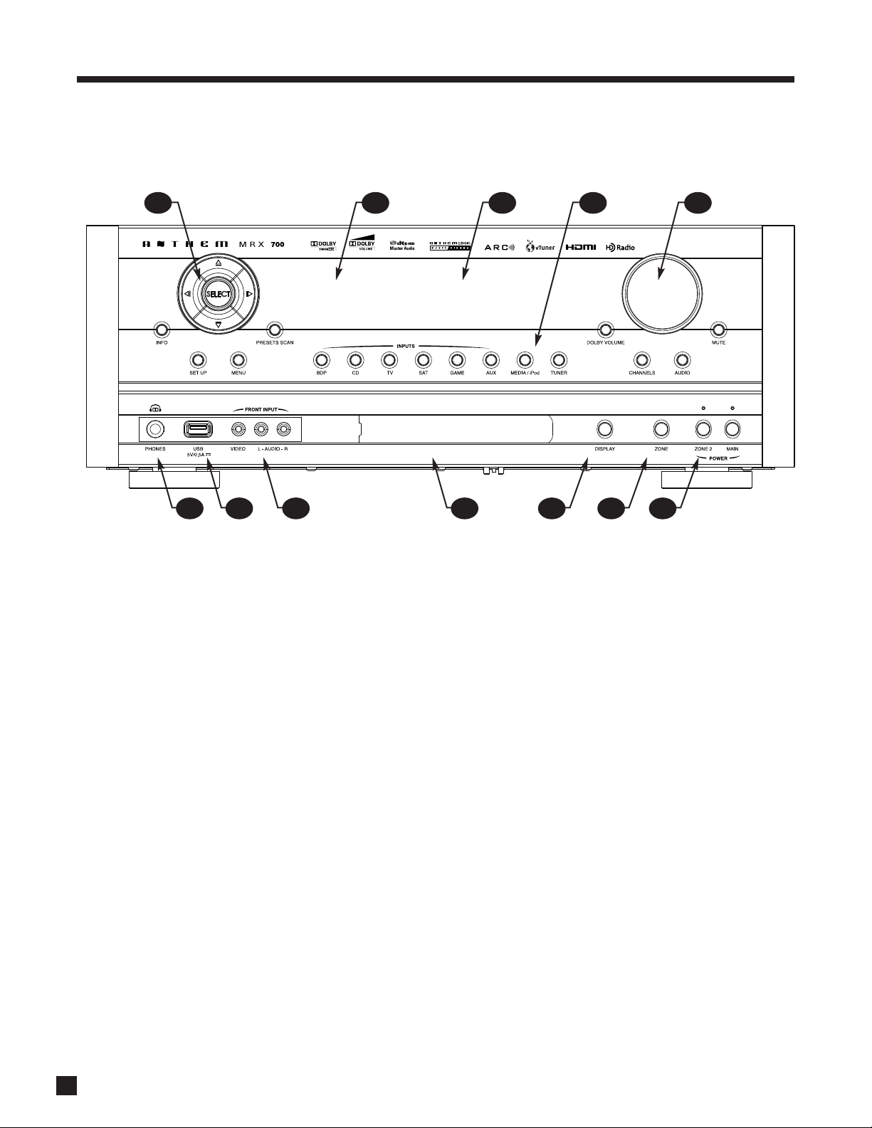
1.3 FRONT PANEL (MRX 700 US model shown, others are similar)
532 41
8 7 612 10 911
1 – Navigation buttons for setup and multimedia
2 – Remote control sensor location
3 – Display
4 – Input selection
5 – Volume and level functions
6 – Power on / standby
*Uses Dolby Headphone to process 5.1-channel content so none of it is lost in the 2-channel headphone downmix.
For a larger diagram see inside back cover.
7 – Main / Zone 2 selection
8 – Display brightness
9 – Sliding cover for front connections
10 – Front AV input
11 – USB input (5VDC/0.5A) (not available on MRX 300)
12 – Headphone connection*
2
Page 11

1. INTRODUCTION continued …
1.4 FRONT PANEL DISPLAY
MAIN Display Example:
1
BDP 1080p
Dolby TrueHD 3/4
4
1 – Source selection.
2 – Video input
3 – Number of front/surround channels.
4 – Audio format.
Tuner Display Example:
resolution.
1
2
3
2
FM-01 101. 3
Stereo -35
1 – Band and preset.
2 – Frequency. AM is tuned to nearest 10 kHz (120V model) or 9 kHz (230V model).
3
Page 12

1. INTRODUCTION continued …
1.5 REAR PANEL (MRX 700 US model shown, others are similar)
2 31 4 5 9
171820 19 16 14 13 12 1115
1 – Connection for optional MDX 1 dock
2 – HDMI output
3 – Ethernet connection (not available on MRX 300)
4 – USB input (5VDC/0.5A) (not available on MRX 300)
5 – HDMI inputs
6 – Tuner antenna connections
7 – Coaxial and optical digital audio outputs
8 – Composite video inputs
9 – Coaxial and optical digital audio inputs
10 – Component video inputs
76 8
11 – Switched AC outlet (50W maximum output)*
12 – AC input
13 – Component video outputs (via scaler)
14 – Speaker connections
15 – Record audio outputs
16 – Analog audio L/R inputs
17 – RS-232 interface (bidirectional)
18 – Main pre-out connections
19 – IR and trigger connections
20 – Zone 2 audio outputs
10
*AC outlet may not be available depending on country
For a larger diagram see inside back cover.
4
Page 13
1. INTRODUCTION continued …
ZONE 2
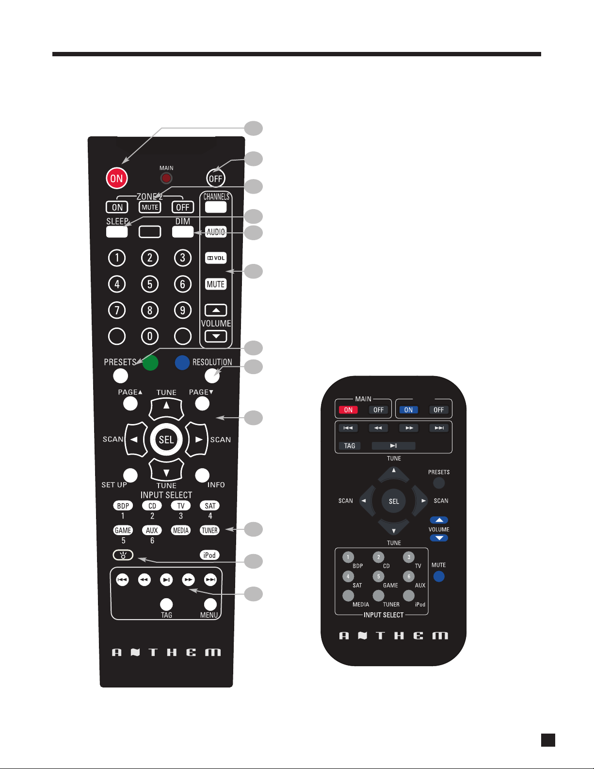
1.6 REMOTE CONTROLS
1
2
3
4
5
6
1 – Main zone power on
2 – Main zone power off
3 – Zone 2 power and mute
4 – Sleep control
5 – Front panel dimmer control
6 – Main zone audio controls
7 – Tuner presets control
8 – Main video output resolution control
9 – Navigation and tuner controls
10 – Input selectors
11 – Backlight control
12 – Multimedia controls
7
8
9
10
11
12
Zone 2 remote control:
Note: MRX 300/500/700 cannot access MEDIA from Zone 2
5
Page 14

1. INTRODUCTION continued …
1.7 SPEAKER PLACEMENT
The illustration below shows typical 7.1-channel speaker placement. The subwoofer can be placed in any
location where severe resonances are prevented – details are in section 3.11 under “Quick Measure”.
back speakers are not
used in a 5.1 system
The illustration below shows 7.1-channel speaker placement for use with Dolby Pro Logic IIz.
6
Page 15

2. CONNECTIONS
2.1 VIDEO CONNECTIONS
To configure inputs see section 3.5 and to configure video outputs see section 3.1.
HDMI:
Video is sent with audio from source components to the receiver. Maximum video resolution is 1080p60.
Connect MAIN HDMI output to a display with HDMI input – one with High-bandwidth Digital Content
Protection (HDCP) is required to display copy-protected material. Note that disc players usually enable
HDCP even on home movies where copy protection was not seleced.
Before calling for technical support due to bad, intermittent, or no picture via HDMI:
1080p uses twice the bandwidth that 720p and 1080i do – make sure that the cable is suitable for the
application otherwise the picture may contain pixel dropouts or not play at all.
Use High Speed HDMI cables. This is a requirement for all connecting devices including extenders
when connecting a display that supports 1080p. Connecting devices that worked in an older setup may
not work with Deep Color. If the source allows Deep Color to be turned off, start troubleshooting by
turning it off. 12-bit Deep Color that works at 1080p24 may not work at 1080p50 or 1080p60.
Be careful when connecting HDMI cables. The connector should easily slide in the jack – do not insert
it on an angle and do not force it. Each connector contains 19 delicate pins and damaged pins can
damage jacks. Such damaged jacks are not covered by warranty. If your HDMI cables have been
connected enough times that they are about to wear out, we recommend that you replace them.
If using adapters and are having a connection problem, start troubleshooting by eliminating the adapter.
Cable and satellite receivers: Many disable their component video output once HDMI is connected. To
use the cable/satellite box in a secondary zone that uses component video, connect the box to the
receiver via component, not HDMI.
Older cable and satellite receivers: HDMI connection may be problematic especially when output
resolution changes between SD, 720p, and 1080i according to the channel. In such a case use
component video connection instead, with coaxial or optical connection for audio.
Component Video:
Component video uses three coaxial cables and has a maximum resolution of 1080p when unprocessed or
480p when the source is copy-protected with Macrovision. Maximum input resolution is 1080i60 where the
input is processed or converted to HDMI.
Composite Video:
Maximum resolution is 480i (NTSC) / 576i (PAL). This traditional format combines the black/white and color
information for transmission on a single coaxial cable. To be displayed, the information has to be filtered and
separated, a process that degrades video quality.
7
Page 16

2. CONNECTIONS continued …
2.2 AUDIO CONNECTIONS
Digital Audio Inputs and Outputs:
Digital audio sources can be connected with a coaxial, optical, or HDMI cable. These carry 2-channel PCM,
Dolby Digital, and DTS. The HDMI inputs also accept up to eight channels of PCM.
Use the HDMI inputs if your display has HDCP-compliant HDMI or DVI input, otherwise use the coaxial or
optical inputs. Any digital input can be assigned to any number of sources that are set to digital. Should you
need audio from the HDMI output to your display, it’s 2-channel PCM. To change digital audio connection
from factory default, see section 3.5.
Digital Rec-Out can provide a signal to the digital audio input of a Mini Disc recorder, CD recorder etc. from
any coaxial or optical audio source.
Analog Audio Inputs and Outputs:
Analog audio connections are made with RCA connectors. To use ZONE2 or RECORD analog outputs,
connect digital and
Speakers:
Connect using speaker wire. US models also allow use of banana plugs. Note that on the rear panel the AUX
speakers are labeled as SB (surround back for conventional 7.1-channel system), VH (vertical height for front
ceiling speakers using Dolby Pro Logic IIz), and Zone 2 left and right speakers.
analog audio and video from digital sources (there is no output without analog input).
Connect the positive (+) connection on the speaker to the positive (+) binding post on the appropriate
receiver channel, and the negative (–) connection on the speaker to the negative (–) binding post on the
same receiver channel, using cable that is insulated to handle the maximum output of the receiver.
Carefully remove
insulation using
a wire stripper.
Do NOT connect more than one speaker to each receiver channel. Be sure that power is turned off when
connecting or disconnecting anything and that the speakers are rated for use with this receiver.
2.3 ANTENNAS
To connect the AM loop antenna, press the spring-loaded tabs of the AM ANTENNA connector and insert
the bare ends of the two wires. Move the antenna until best reception is found.
For the FM antenna, use the FM ANTENNA connector. Later, when unit is operating move the antenna to find
best reception. If your cable company provides FM service, you can connect the cable to the receiver.
8
Page 17

2. CONNECTIONS continued …
2.4 ETHERNET (not available on MRX 300)
This connection is required for Internet radio. Connect your router using CAT 5 cable or a wireless bridge.
2.5 ANTHEM MDX 1 DOCK (optional)
Connect using the special cable that’s supplied with the dock. Further connection instructions are provided
with the dock.
2.6 12 VOLT TRIGGER
If another system component has a trigger input it can be activated by the receiver.
Connect the receiver’s trigger output using a cable with 3.5mm mini plugs.
The receiver provides flexible trigger options. Through the setup menu, you can specify the conditions for
enabling triggers (see section 3.9).
2.7 INFRA RED INPUT
An external IR receiver allows the remote control to be used from another location in your home. Once an IR
receiver is wired to another room, connect it to the IR IN input.
2.8 INFRA RED OUTPUT
IR emitters allow control of your source components from any location in your home that has an IR receiver
connected to the receiver. After positioning the IR emitter according to its instructions, connect it to IR OUT.
Commands through the rear panel IR IN are re-transmitted through IR OUT.
2.9 SWITCHED AC OUTLET
This can be used to power smaller devices which require no more than 50W. Power at the outlet is turned
off when the receiver is turned off.
2.10 POWER
Connect the power cord to the receiver and the power source.
9
Page 18

2. CONNECTIONS continued …
Example 1: Disc player to receiver to main display
HDMI IN
AUDIO
OUT
L
R
Connect
if using
Zone 2
or Rec
HDMI
OUT
Connect
for Main
Connect if using
digital Rec-out or
if source’s video
output is DVI
COAX
OUT
Connect if using
component
monitor video
output
YPbPr OUT
10
Page 19

2. CONNECTIONS continued …
Example 2: A/V recorder to receiver
For Zone 2 and Rec you
must use the same input
type as the output type,
except coaxial and
optical audio which are
interchangeable.
L
R
AUDIO
OUT
AUDIO
IN
L
R
VIDEO
VIDEO
OUT
IN
11
Page 20

12
Page 21

3. SETUP
For optimum performance and enjoyment, your receiver should be properly set up. This may appear like a lot
of work but keep in mind that most settings do not need to be changed from defaults.
The most important things are entering information about your display and speakers if the defaults do not
apply, and the distance from each speaker to the listening area. The rest is Anthem Room Correction-related
and preference – the listening mode presets, for example, should be set up after you have played various
sources and have decided which surround modes you like best.
Remote Control Front Panel
HOW TO NAVIGATE IN THE SETUP MENU
• Press SETUP to enter or exit.
• Use the 56 and 34 buttons to scroll through menus and selections.
• Press SELECT to set a selection.
Upon entering the setup menu your display will usually show the menu below if connected with HDMI. Up to
eight menu items are displayed at once – for clarity this manual shows each menu with all items. On-screen
display is recommended although the front panel shows similar information, one item at a time.
If on-screen display is not shown on your TV, use the front panel display to set appropriate video output.
Main Menu
Video Output Configuration
Speaker Configuration
Audio/Video Setup and Presets
Displays/Timeout
Trigger Configuration
General Configuration
System Information
Quick Setup
4
Press Setup to exit
34
34
To go to a submenu, highlight a menu item and press4. To return to the previous menu press3. Up to four
small arrows on each screen’s lower right indicate next possible steps.
13
Page 22

3. SETUP continued …
QUICK SETUP
Highlight Quick Setup and press4. Up to four questions will appear on-screen, one at a time in sequence,
with multiple choice answers depending on previous answer:
• Do you use an HDMI/DVI TV? No / Yes
• Component video output resolution? 480i / 480p (120V model) or 576i / 576p (230V) / 720p / 1080i
• Do you have a subwoofer? No / Yes
• How many additional speakers do you have? 7 (ceiling) / 7 (back) / 5 / 2
For detailed setup, follow the rest of section 3.
3.1 VIDEO OUTPUT CONFIGURATION
Highlighting Video Output Configuration then pressing4displays this menu:
Video Output Configuration
Configuration 1 of 2
Name VidOut 1
Resolution Auto
Video Output Configurations:
Two configurations can be set up, each assignable to each input. Only one is needed in most cases. The
second can be used with a secondary display that needs different a different setting, for example one
connected to Monitor component video output. Output assignment by source is explained in section 3.5.
Name:
Each configuration can be renamed using the navigation keys, with names up to 8 characters long.
Resolution:
Resolution is represented as follows:
1080p
number of pixels or lines from top to bottom
The default is Auto which sets resolution according to highest capability reported by the display’s HDMI
connection. If you wish to set a different resolution and it matches that of your TV, the choices are 480i/480p
(US model) or 576i/576p (EU model), 720p, 1080i, 1080p, or Through in which the receiver’s output resolution
is the same as the source’s resolution.
scan type: p=progressive, i=interlaced
14
Movies on Blu-ray discs can be shown with the original 24 frames per second, as shot by the movie camera.
If your Blu-ray player can be set to output 1080p-24, also known as 24p mode, and your TV accepts this
format, the receiver will select 1080p-24 when such a source is playing (cannot be selected manually). This
results in smoother image motion.
To prevent loss of video output as you scroll through settings, a resolution selection change does not take
place immediately. Once you leave this menu, it asks for confirmation – use the34 buttons to change to Yes,
then press SELECT. To put a change into effect before leaving the menu, press SELECT then confirm.
Page 23

3. SETUP continued …
3.2 SPEAKER CONFIGURATION
This menu allows you to enter information about your speakers so that sounds from sources are not lost or
distorted. If your source components have bass management and time alignment, turn them off by setting all
channels “large” and to the same distance in the source components.
Speaker Configuration
Bass Management
Listener Position
Level Calibration
Aux Output Main Back
4
Skip Bass Management and Level Calibration if using Anthem Room Correction (ARC) with all inputs.
Aux Output:
Select Main Back, Main Ceiling, or Zone 2. The Main Ceiling setting enables use of Dolby Pro Logic IIz which
improves the spatial experience, especially for games, using height speakers above the front left and front
right speakers.
If you are using 5.1 speakers, use the Surround outputs and set Aux to Zone 2 so no sound is lost.
Bass Management:
The bass manager is a crossover that divides audio in two frequency bands suitable for subwoofer/satellite
speaker systems, resulting in lower bass level for satellite speakers and no midrange/treble in the
subwoofer. If your subwoofer has a crossover, it should be bypassed – set its frequency control to the
highest frequency to avoid a double crossover.
The receiver memorizes two configurations – each is assignable according to input. Normally, only Movie
configuration is needed. Highlighting Bass Management then pressing4displays this menu:
Bass Management
Configuration Movie
Front Small 80 Hz
Center Small 80 Hz
Surround Small 80 Hz
Aux Small 80 Hz
Subwoofer On
Small or Large:
Most speakers should be set to Small and used with a subwoofer unless they use large drivers that play deep
bass accurately. Even then, the question is which speaker can produce deeper and cleaner bass at higher
output? It should be the subwoofer, which besides being made for bass, has the advantage of flexible
positioning in the room to help control boominess.
15
Page 24

3. SETUP continued …
Crossover Frequency:
A crossover does not cut frequencies off like a cliff, but rolls them off according to a slope. If set to, for
example, 80 Hz your main speakers will still play lower frequencies – they just won’t have to play them as
loudly. This also lightens the load on the amplifier leaving extra power for mid and high frequencies.
Select 60, 80, 100, 120 or 150 Hz according to the low frequency capability of your speakers.
“Off” setting for:
• Center – the center channel plays from the L/R fronts.
• Surround – the L-Surround channel plays from the L-Front channel and the R-Surround channel
plays from the R-Front channel (except Dolby Pro Logic modes).
Subwoofer:
The subwoofer plays two things – LFE (Low Frequency Effects) channel in multichannel soundtracks and
bass from channels set to Small. Select On or Off.
Bass response highly depends on room acoustics and experimentation with subwoofer placement is
recommended. If you will not use ARC Quick Measure start by temporarily placing the subwoofer in the
listening area, play some music with a range of bass and walk around the room. Positions where the
bass range sounds smooth are suitable for permanent subwoofer placement as long as decor allows.
3.3 LISTENER POSITION
The Listener Position menu lets you enter the distance between each speaker and the listening area. The
channel with the greatest distance setting will have no delay while channels with shorter distance settings
will be delayed according to their setting. This way, sound reaches the listening area at the same time from
all speakers, and proper imaging can be achieved.
Listener Position
Measurement Units Feet
Front Left 12 ft
Center 12 ft
Front Right 12 ft
Surround Right 8 ft
Surround Left 8 ft
Subwoofer 12 ft
Aux Right 6 ft
Aux Left 6 ft
Measurement Units:
Feet (ft) or Metres (m).
16
Distance Adjustment:
Enter the distance between your primary listening area and each speaker. Range is 0-30 ft in 1 ft increments
or 0-9 m in 0.3 m increments.
Page 25

3. SETUP continued …
3.4 LEVEL CALIBRATION
Level Calibration uses internal test noises to match speaker output levels at the listening position. These
noises are also a way of checking system connections between receiver, amplifier, and speaker. Audio
calibrations from home theater setup discs are not recommended – some use incorrect methods.
A sound pressure level (SPL) meter with C-weighting is recommended if not using ARC. Measure from the
listening position, pointing the meter up and holding it away from your body to prevent reflections.
The CHANNELS control does not
change settings in this menu – it provides on-the-fly adjustment
memorized according to input format in case a source needs it.
Level Calibration
Dolby Volume Leveler Amount Low
Dolby Volume Calibration Offset 0 dB
Noise Sequence Off
Front Left 0 dB
Center 0 dB
Front Right 0 dB
Surround Right 0 dB
Surround Left 0 dB
Movie Subwoofer 0 dB
Music Subwoofer 0 dB
Aux Right 0 dB
Aux Left 0 dB
No adjustments in this menu are necessary when using ARC,
except setting Dolby Volume Leveler Amount according to preference.
Dolby Volume Mode (MAIN only):
Dolby Volume makes content with large differences in volume easier to listen to by analyzing it and
intelligently adjusting two things – level and frequency response. It does this continually without causing
pumping and breathing artifacts that are common with traditional dynamic range compressors. In doing so,
the volume setting is taken into account as is our hearing’s declining sensitivity to the lowest and highest
frequencies relative to the midrange as their levels drop. The result is that the perceived frequency response
remains constant while making quieter parts of the content more listenable.
Dolby Volume Leveler Amount:
The leveling amount that Dolby Volume provides can be set from Low to High with nine “medium” steps
between, or Off. Play various sources before finding your preferred setting. When Dolby Level is Off the
frequency response adjustment still applies unless Dolby Volume is also Off.
Dolby Volume Calibration Offset:
If using an SPL meter, adjust level so it reads 75 dB. This normally needs no adjustment from 0 dB.
17
Page 26

3. SETUP continued …
Test Noise Sequence:
Test noise plays from one speaker at a time, changed by using the 56 buttons.
Level Calibration of each channel:
Balances speaker levels to one another. If you’re calibrating by ear, use the remote control and sit in the
listening area when adjusting. If using an SPL meter, adjust level so it reads 75 dB for each channel. If Noise
Level is set while Front-L is at 0 dB, no adjustment of Front-L is needed since the output is the same. If using
a powered subwoofer, make a rough adjustment with its input level control before setting sub level in this
menu or using ARC. Speakers set to Off in the Bass Management menu are skipped.
If using multiple subwoofers they must be balanced to one another before further audio setup,
including when using ARC. Play the subwoofer test noise with only one subwoofer connected at a time.
Set its input level dial so the SPL meter reads 71 dB from the listening area if using two subs or 67 dB if
using four subs. Repeat this for the remaining subs. When all are connected the result should be around
75 dB. ARC sets the final level for the group of subwoofers. If not using ARC, change the level of all subs
equally for a combined result of 75 dB SPL.
To fine-tune the level or phase of each sub relative to one another, listen to FM “shhhh” noise through
the subwoofers only by disconnecting the receiver’s speaker outputs, and adjust (or better yet have
someone else adjust) the sub’s level and/or phase control until bass is loudest in the listening area. If
your subwoofer has a polarity switch you can instead temporarily invert polarity, adjust according to
lowest bass output (this might be easier to hear than aiming for highest output) and then restore the
switch to the normal position which results in maximum output.
Procedure for Manual Test Sequence (not needed when using ARC):
• Set NOISE SEQUENCE to Manual.
• Press the 56 buttons to go from speaker to speaker.
• As each speaker plays, use the 34 buttons to adjust its loudness relative to other speakers.
• Press3to stop the test noise.
18
Page 27

3. SETUP continued …
3.5 SOURCE SETUP
Inputs and preset listening mode presets are configured in this section.
Audio/Video Setup and Presets
Main Source Setup
Advanced Source Setup
Listening Mode Presets
Video Mode Presets
Audio Rec Device Connected to None
Video Rec Device Connected to None
HDMI Audio Output AVR
HDMI CEC Off
4
Audio / Video recording device connected to:
Select the input that the output of your recording device is connected to.
HDMI Audio Output:
When set to AVR (recommended), no audio is sent to the TV. When set to AVR+TV or TV, audio is sent to the
TV but the audio format for all playback is according to the TV’s capability – 2-channel not
multichannel.
HDMI CEC:
When On, allows controlling one HDMI-connected component using another’s remote control, as long as
CEC is also on in the other components. Note that when component brands are mixed this control system
may not be reliable.
Selecting Main Source Setup displays this menu:
Main Source Setup
Source 1 of 9 (BDP)
Name BDP
Video Output Configuration VidOut 1
Main Video Input HDMI1
Main Audio Input Dig HDMI
Bass Manager Movie
Name:
The source names that appear on the front panel display and some other menus can be changed, up to 8
characters long. Example: Rename “BDP” to “Blu-ray”.
• Highlight “Name” and press SELECT. The first character (a space) will be highlighted in red.
• Use the 56 buttons to change characters. Change the first one to “B”.
• Use the 34 buttons to move to each remaining character and complete the renaming.
• Press SELECT to return to the menu.
19
Page 28

3. SETUP continued …
Video Output Configuration (MAIN only):
For the source, select the most appropriate configuration that is set in Video Output Configuration menu.
Main Video Input / Main Audio Input / Bass Manager:
Assign input connections and bass management to be used for main output when the source is selected.
Selecting Advanced Source Setup displays this menu:
Advanced Source Setup
Source 1 of 9 (BDP)
Main/Rec Composite Input Composite 1
Main/Rec Analog Audio Input Analog 1
Z2 Composite Input Composite 1
Z2 Analog Audio Input Analog 1
Lip-Sync Delay 0 ms
Anthem Room Correction Not Available
Bass 0 dB
Treble 0 dB
Dolby Volume Mode Off
Dolby Volume Half Mode Off
Dolby Volume Cinema Reference Mode Off
Main/Rec Composite and Analog Audio inputs:
Assign input connections to be used for analog Rec output when the analog A/V source is selected in Main.
Zone 2 Composite and Analog Audio inputs:
Assign input connections to be used for Zone 2 output when the analog A/V source is selected in Zone 2.
Lip-Sync Delay (MAIN only):
If audio is heard before its corresponding image is seen, you can set up to 150 milliseconds of audio delay –
set using synchronization test disc or trial and error. Movies are not the best test because sounds including
dialog are usually re-recorded after the filming is completed, and can be slightly out of sync at various points
in the recording.
Room EQ (MAIN only):
Not Available becomes On once the ARC microphone procedure is completed. Can also be turned Off
although this defeats one of the receiver’s biggest strengths.
Bass / Treble (MAIN only):
If a source needs a full-time tone adjustment for better sound, it can be done here.
Dolby Volume Mode (MAIN only):
Select On or Off to enable or disable Dolby Volume.
Dolby Volume Half Mode (MAIN only):
When on (recommended), frequency response is not adjusted when volume control is set higher than 0 dB.
20
Dolby Volume Cinema Reference Mode (MAIN only):
When on, Dolby Volume adjusts playback level according to reference level used in movie production.
Page 29

3. SETUP continued …
3.6 LISTENING MODE PRESETS
Listening mode presets are applied when the source is selected. Each input format except mono has a
setting. To disable presets, set them to Last Used.
For descriptions of surround modes and when they’re applicable refer to section 4.6. Spend some time
listening to various modes with various sources before deciding which presets to use.
Listening Mode Presets
Source 1 of 9 (BDP)
2.0 AnthemLogic-Cinema
2.0 Dolby Digital Surround PLIIx Movie
Multi Channel PCM PLIIx Movie
5.1 Dolby Digital None
Dolby Digital Surround EX None
5.1 DTS None
DTS-ES None
2.0:
For stereo input select Stereo, AnthemLogic-Music, AnthemLogic-Cinema, PLIIx Movie, PLIIx Music,
PLIIx Game, PLII Movie, PLII Music, PLII Game, Dolby PLIIz, Neo:6 Music, Neo:6 Cinema, Dolby VS Wide,
Dolby VS Reference, All Channel Stereo, Last Used.
The following apply to digital inputs only:
2.0 Dolby Digital Surround:
For surround-flagged Dolby Digital 2.0 material select Stereo, PLIIx Movie, PLIIx Music, PLIIx Game,
PLII Movie, PLII Music, PLII Game, Dolby PLIIz, Dolby VS Wide, Dolby VS Reference, Last Used.
Multi Channel PCM:
Set your playback preference for multichannel PCM (via HDMI): None, PLIIx Movie, PLIIx Music, PLII Movie,
PLII Music, Dolby PLIIz, Neo:6 Cinema, Neo:6 Music, Dolby VS Wide, Dolby VS Reference, Last Used.
5.1 Dolby Digital:
Set your playback preference for Dolby Digital 5.1 material: None, PLIIx Movie, PLIIx Music, Dolby PLIIz,
Dolby Digital EX, Dolby VS Wide, Dolby VS Reference, Last Used.
Dolby Digital Surround EX:
For material encoded in Dolby Digital Surround EX: None, PLIIx Movie, PLIIx Music, Dolby PLIIz, Same As
Dolby D-5.1, Dolby VS Wide, Dolby VS Reference, Last Used.
5.1 DTS:
For DTS: None, Neo:6 Cinema, Neo:6 Music, Dolby PLIIz, Dolby VS Wide, Dolby VS Reference, Last Used.
DTS-ES
For DTS-ES: None, Dolby PLIIz, Same As DTS-5.1, Dolby VS Wide, Dolby VS Reference, Last Used. Note that
for ES Discrete, this setting is overridden and playback is in 6.1.
21
Page 30

3. SETUP continued …
3.7 VIDEO MODE PRESETS
Compensation is provided here for less than ideal video sources that cannot be adjusted internally. If
possible check performance of each video source through test patterns. Unfortunately, these days the
sources that need adjustment most are also the least likely to have test patterns available for them, for
example bad satellite channels.
Video Mode Presets
Brightness:
This controls black level. If the picture from a source appears hazy, lower brightness. If differences in dark
areas of the picture cannot be made out, increase brightness.
Source 1 of 9 (BDP)
Brightness 0
Contrast 0
Color 0
MPEG Noise Reduction Off
Cross Color Suppression On
Film Mode Detection On
Contrast:
This controls white level. If bright scenes appear too bright, lower contrast so differences in bright areas can be
made out. If the picture appears dull, increase brightness but not to the point that bright white objects such
as clouds on a sunny day lose detail.
Color:
This controls the amount of color. Adjust so familiar colors such as skin tones appear natural.
MPEG Noise Reduction:
Enable if compressed digital video sources have an abundance of motion artifacts.
Cross Color Suppression:
Try enabling if still images that have gone through a composite video stage contain rapidly flashing rainbowcolored artifacts.
Film Mode Detection:
This should almost always be left on. Film mode discerns between interlaced 60 Hz sources recorded with a
video camera and those that originated with 24 frame per second film, and deinterlaces accordingly. Unusual
sources can cause the deinterlacer to put out an erratic picture – in such a case try disabling film mode.
22
Page 31

3. SETUP continued …
3.8 DISPLAYS / TIMEOUT
This menu allows you to configure on-screen display, front panel display, and selection time.
Displays/Timeout
Display Brightness:
Lets you select between bright, dim, or no front panel display.
Front Panel Wake Up:
If Display Brightness is set to Dim or Off, it can be made to change to a brighter level while you make any
adjustment – choose None, Up 1 brightness level, or Bright. When None is chosen and the display is off, it
will behave as if set to Up 1 to prevent confusion as to whether the power is on or off.
Display Brightness Dim
Front Panel Wake Up Up 1
Display Timeout 5 s
Video Mute Black
Status Message On
Status Message Timeout 3 s
Setup Menu Timeout 5 min
Display Timeout:
This is the time that elapses after an adjustment is made in any path. After that, on-screen text disappears,
the front panel becomes dim, and the regular MAIN display returns. Adjustable from 1 to 15 seconds.
Video Mute:
For when there’s no video input, select the “no signal” output – black, magenta, or blue screen.
Status Message:
To disable on-screen info shown when changing volume, source, etc, turn this setting Off.
Status Message Timeout:
Set the amount of time that the status message remains on-screen.
Setup Menu Timeout:
Set the amount of time that the setup menu remains on-screen, up to 15 minutes. It should not be left on long
enough to damage the display, if it is a type that is prone to image retention (burn-in).
23
Page 32

3. SETUP continued …
3.9 TRIGGER CONFIGURATION
When the receiver’s trigger output is connected to the trigger input of another component, such as an
amplifier or projector, the receiver can turn it on or off according to the trigger’s setup. For components that
do not have trigger inputs, a triggerable power bar may work (see your dealer).
Trigger Configuration
Main Z2
Power * *
BDP NA NA
CD NA NA
TV NA NA
SAT NA NA
GAME NA NA
AUX NA NA
MEDIA NA NA
TUNER NA NA
iPod NA NA
Trigger Delay 2 s 0-15s (1s step)
In the example shown, the trigger activates while Main or Zone 2 power is turned on. Trigger outputs can
also be set to activate according to source instead of Power.
After highlighting Power or a source, press SELECT and use the 34 buttons to select Main or Z2. To set the
condition, use the 56 buttons to change the “NA” to a “-”.
Trigger action can be set to be delayed up to 15 seconds, in 1-second steps.
Changes to the trigger setup do not take effect until exiting from the setup menu, to avoid unnecessary rapid
turning off and on of triggers while making changes.
24
Page 33

3. SETUP continued …
3.10 GENERAL CONFIGURATION
This menu allows you to define the power-on volume settings, save.load settings, and configure RS-232.
General Configuration
Power On Volume
Load Factory Defaults
Save/Load User Settings
RS-232 Baud Rate 115200
Power-On Volume:
When you turn Main or Zone 2, the volume for each will be at the levels you have set in this menu. This
prevents surprises when not knowing the volume someone had set when turning the receiver off, then
having the power-on volume be too loud or quiet. The default is -35 dB.
Load Factory Defaults:
After selecting and confirming, all menu settings will be reset.
Save/Load User Settings:
After selecting Save User Settings and confirming, all menu settings will be stored. If you change settings
later and want to recall the saved settings, select Load User Settings and confirm.
RS-232 Baud Rate (normally for use only by custom installers):
Select 19200 or 115200.
4
25
Page 34

3. SETUP continued …
3.11 ANTHEM ROOM CORRECTION (ARC)
ARC corrects the effects of reflective surfaces and room boundaries on sound quality by measuring the
response of each speaker relative to the listening area and equalizing it. ARC equalizes response without
stressing the amplifier or speakers and does not downsample the source material to process it. ARC’s filters
are neither graphic nor parametric – ARC is a sophisticated system that flattens response using its ability to
create practically any suitable function, inherently correcting phase effects created by the room.
The default correction range is up to 5 kHz. Although the limit can be changed if needed, a higher one is
generally not advised since the microphone becomes directional at upper frequencies, affecting
measurement accuracy especially if the height of the speaker’s high frequency driver is not at ear level.
ARC also detects how much the room reinforces low frequencies due to its boundaries and pressurization.
This room gain shows as a bump in the target response. ARC does not remove it because if flattened, bass
sounds thin. Ideal anechoic speaker response, a straight line as measured in a special non-reverberant
facility, is not the same as ideal in-room response which normally includes, to varying degree, this room gain.
ARC senses where each speaker’s low-frequency response declines and sets high-pass filters accordingly.
Calibration is set such that average level is the same when comparing EQ “On” vs “Off”. Note that to set
levels ARC uses a midrange band that’s wider than the standard home theater setup noise, which is centered
at 1 kHz and narrow so there’s no chance its level would be reduced by a crossover.
Sample response:
Calculated response after EQ
Measured response before EQ
Target response – dotted line
EQ is also available for my subwoofer(s) – should I use it?
Since rooms and correction systems, the answer varies although it is best to disable the subwoofer’s EQ
before running ARC. If the resulting calculated and target curves resemble each other, there is usually
no reason to use the sub’s EQ. If the curves significantly
EQ and run ARC again to see if it helps. If you have run ARC with the sub’s EQ enabled, ARC must be run
again once the sub’s EQ is turned off.
differ through a wide range, enable the sub’s
26
Multiple Paradigm subs with PBK: Results are often better with PBK run on each sub before using ARC.
Page 35

3. SETUP continued …
Before starting:
• Ensure that the receiver software and ARC software that you will be using are compatible with one
another – check www.anthemAV.com for latest versions. Receiver software installation
instructions are in section 4.11 and in software download.
• Your ARC microphone and its support file are a system. Before a mic can be used for measurement,
its response must be known. Each ARC microphone’s frequency response is measured precisely
and this data is used to create your microphone calibration file.
• Your computer must be running Windows XP or later and have one 9-pin
serial port (for connecting the processor) and one USB port (for connecting
the mic), or
ports and a USB to serial adapter. The Keyspan model USA-19HS adapter is
recommended. Before it can be used its driver must be installed according
to your computer’s operating system. Drivers and installation instructions
can be found at www.tripplite.com.
If using a USB to serial adapter to connect the receiver:
1. It must be one that supports two stop bits – check with adapter manufacturer.
2. Check the adapter manufacturer’s website for the latest driver. If a message warns that the
driver is not Windows-certified as it’s about to be installed, do not use the adapter. Some
“budget” adapters load bad data into the receiver, possibly causing its operation to freeze.
one USB port and one card slot and a serial card, or two USB
3. The virtual port must be assigned to COM1-COM6. If the receiver’s software cannot locate the
receiver, use your adapter’s port manager to check the setting.
• If you are using a laptop computer, check its power settings and battery meter to ensure that
procedures will not be interrupted.
• If the room contains large objects that won’t be present during the system’s normal use, move them
out so ARC doesn’t pick up reflections that won’t be present during normal use.
• While taking measurements it would be best to keep pets and younger or talkative family members
out of hearing range. The measurements reject continuous background noise such as fans but if a
sudden noise is made ARC will indicate that re-measurement is required.
• Two configurations may be saved – one under Movie bass management and the other under Music.
ARC software installation:
Play the ARC CD in your computer’s CD or DVD drive. Instructions will appear on your screen. If your
computer does not allow a CD to auto-run then double-click on the My Computer icon that’s on Desktop,
select the drive that the CD is in to view its contents (you may need to right-click on its icon then select
Explore), and double-click on setup.exe.
The installation will put several files into an Anthem folder on your computer and create shortcuts in your
Start Menu and on Desktop. Example: 200001.cal.
Custom installers: To set up multiple systems using one computer, copy the serialized files from each
ARC CD to this directory after ARC is installed:
My Computer, Local Disk C:\Program Files\Anthem\AnthemRoomCorrection
27
Page 36

3. SETUP continued …
Microphone stand assembly:
Screw the microphone clip onto the tube. Position the clip vertically. Connect the USB microphone cable to
the microphone and slide the microphone into the clip.
Microphone positioning:
During measurement the microphone must point straight up. The microphone’s height is critical to proper
measurement and should be at ear level when seated.
Ideally, the front speakers’ high-frequency drivers should be at approximately the same height as the
listener’s ears but if they aren’t and the result sounds dull or bright, microphone height will have to be
adjusted and measurements repeated.
To adjust the length of the telescoping tube, first loosen its clamp by rotating it counterclockwise.
Five listening area positions are normally measured but this number can be increased up to ten. The first
must be at or just in front of the central seating position. This is also used to set Speaker Calibration levels.
Positions 2 and 3 should be symmetric to the left and the right of the center line, and the same applies to the
remaining positions. If your room has less than five seating positions, measurements must still be taken from
five positions at least 2 feet (70 cm) apart to ensure optimal sound.
Measurement:
• Connect the microphone and the receiver to the computer.
• Set the microphone in the first position. Don’t stand near the microphone while sweep tones are
playing otherwise reflections from your body may cause bad measurements.
• Run Anthem Room Correction by selecting it from the Start Menu or double-clicking the Desktop
shortcut and select Automatic mode. The program will guide you through the remaining steps and
at the end will load the correction data to your receiver. The process takes about 20 minutes
depending on the number of measurements.
• Once the ARC program is finished, you can disconnect the computer. Turn on the receiver and set
“Room EQ:” On/Off in the Source Setup menu according to each source. If you made measurements
for a Music configuration, assign Bass Manager accordingly.
• Save your settings in the Save / Load Settings menu. Note that changing the Sub crossover in the
Bass Management menu affects only Room EQ “Off” sources.
Quick Measure – speaker position helper:
If the subwoofer’s position is flexible you can try this before running ARC. Proceed as above but select
Manual mode instead of Automatic. Under “Tools” select Quick Measure then click on Connect, select
Subwoofer or any other speaker if its position is also flexible, and click Start. After approximately 10 sweeps
the graph will show a live update of the uncorrected measurement. Try different locations for the speaker
and leave it where the uncorrected graph is flattest. Once this is determined, run ARC normally.
28
Page 37

3. SETUP continued …
Manual mode:
A file created in Automatic mode can be opened in Manual mode to change correction range and room gain.
To do this, change Targets then click on Calculate, then Upload.
Since rooms and systems vary the only advice that Anthem technical support can provide without being
at your house to hear your system is to use the auto-detected settings. The alternative is trial and error.
To change the amount of room gain, the Force checkbox has to be checked for the manually entered change
in dB to take effect once clicking on Calculate. Auto-detected room gain will be at or near 0 dB if bass
absorbers are used or the in-room response of the speakers shows no such gain.
To restore auto-detected settings, click on Auto Detect then Calculate.
Clicking on Erase uploads flat parameters.
Can one set of measurements be used across Movie and Music speaker configurations but with
different settings applied? Can the subwoofer be disabled only in the Music configuration?
The answer to both questions is yes.
• When measuring (Automatic or Manual), set the Music configuration to be Same As Movie.
• In the Manual mode Targets panel change settings as desired.
• To omit the subwoofer, change its frequency to No Speaker by making it lower than 25 Hz. This
can be done with the scroll arrow or by removing the frequency with the cursor and Backspace
key on the computer’s keyboard. Removing the center or surround speakers is not necessary for
listening to 2-channel sources in stereo – if a surround mode is not selected (section 4.8), sound
will not come from the center and surround speakers.
Updating ARC:
Check www.anthemAV.com periodically for ARC software updates. The download contains revision history,
which may also indicate that the receiver requires an update for the ARC version to work correctly.
If a newer version is posted and you would like to use it, check your current version:
• Run Anthem Room Correction.
• Click on About. The version number will be displayed.
Proceed only if your version is not the latest:
• Download the latest software from our web site to Desktop.
• When download is complete, right-click on the downloaded .zip file and extract it to Desktop.
• Open the extracted folder and double click on setup. Software installation instructions will appear
on your screen. If you are installing ARC on the computer for the first time, copy your serialized
file(s) from your software CD to the extracted folder on Desktop before double-clicking on setup.
This way they will be added to Program Files as the software is installed.
• When installation is complete, you can delete the downloaded file and the extracted folder.
To use a measurement made with a previous version with a newer version that has changes in processing,
open it in Manual mode, click on Calculate then Upload.
29
Page 38

3. SETUP continued …
3.12 MULTIMEDIA
iPod (optional MDX 1 dock required):
To set up iPod connection use on-screen display. First, use input selection on front panel or remote to select
iPod input. If using the front panel input selection, the button may have to be pressed more than once to cycle
through Internet Radio, USB, and iPod.
Once iPod input is selected, use navigation keys to select iPod Settings. Here you can select iPod audio and
video output type. For audio connection, select Digital if using your iPod or iPhone exclusively for music
playback in the main zone (digital option is not available on MRX 300). This provides the purest sound,
bypassing the analog section in the iPod/iPhone. Select Analog if you will be playing video (this prevents lipsync issues) or if you will be sending audio to Zone 2.
Select S-Video if your iPod video player is an older model that does not have Component video output.
If audio or video output type is changed while iPod / iPhone is docked, it must be re-docked for the
change to take effect.
vTuner Internet Radio (not available on MRX 300):
vTuner finds a very large number of internet broadcasts and organizes the stations. Supported formats are
mp3 and aac (wma is not supported).
Initial setup: Connect receiver to Internet-enabled Ethernet and select Internet Radio through the MEDIA
input selector (it may need to be pressed 2-3 times as it cycles through Internet Radio, iPod, and USB). If a
firewall is preventing the receiver from connecting to the Internet, change settings in the firewall so the
receiver’s MAC address is allowed. The MAC address is displayed on-screen in the network settings.
Optional online setup: You may find it easier to organize favorites through your computer. To do so, select
Internet Radio, through the MEDIA input selector then press Select. Once you do this the on-screen display
will display “Get access code”. Use this 8-digit code to register on http://anthem.vtuner.com (no “www”).
Your computer screen will display the same info that the receiver’s on-screen display does, but more is
shown at once making it easier to browse and select favorites, and stream type and bit rate are also shown.
After registering you can select favorite stations and create groups to add your favorites to. These will
instantly appear in the receiver’s on-screen display.
30
Page 39

4. OPERATION
ZONE 2
4.1 POWER ON AND OFF
Main and Zone 2 have separate power controls. Volume comes on according to setup menu setting.
4.2 ZONE SELECTION
During the timeout period after pressing ZONE, select Zone 2 source. This routes analog audio
and composite video sources to another part of your home.
4.3 SOURCE SELECTION
Select a source through the input buttons. Pressing MEDIA repeatedly cycles, according to availability of
these sources, through Internet Radio and USB on the remote control, and Internet Radio, iPod, and USB on
the front panel. The remote control MEDIA buttons have no function on the MRX 300.
31
Page 40

4. OPERATION continued …
4.3.1 TUNER
AM/FM Tuning:
After selecting the desired band by pressing TUNER, use the 56 buttons to change frequency.
AM/FM Presets:
30 stations can be stored. To store a station press and hold PRESETS on the
remote control then assign a number from 01 to 30. To recall a preset enter the
assigned number. Presets are divided into four banks of six. To scan presets
press PRESETS or PRESETS SCAN then use the 34 buttons.
HD Radio reception (MRX 700 US model only):
If your local radio stations broadcast an HD Radio signal, the receiver will use this signal. In the absence of
such a signal, the receiver will use the regular analog signal. HD Radio broadcasting is a digital method that
results in higher audio quality, preventing static, hiss, pops, and fading sound. As well, song title, album and
artist are displayed during HD Radio reception. For analog-only reception press and hold the Select button.
4.3.2 MULTIMEDIA
The receiver can play audio from these sources:
USB mass storage devices (not available on MRX 300):
Press MEDIA once or twice so “USB” is displayed and connect a USB
flash memory stick, hard disk drive or personal music player with
generic folder-based file system. Supported file types are mp3, wav,
wma 9, wma variable bit rate, wma lossless, and aac-lc.
Mass storage devices must use NTFS, FAT12, FAT16, FAT32, HFS or HFS+ formatting to be compatible. Note
that with NTFS, encrypted files, security IDs, ACLs, and alternate data streams are not supported. With
HFS/HFS+, the system is read-only.
The first time that a mass storage device containing thousands of files is connected, some time may be
needed for indexing before they are displayed. Once indexing is complete, less time will be needed the next
time the same device is connected, unless its formatting is HFS/HFS+. Note that files may not appear in the
correct order when browsing before indexing is complete.
iPod/iPhone (optional MDX 1 dock required):
Once an iPod or iPhone is docked, the song category list appears on-screen. Use navigation keys to browse
and select songs or videos, and green key on remote to set random play or shuffle mode. Early-generation
iPods are not compatible.
vTuner Internet Radio (not available on MRX 300):
Press MEDIA once or twice so “Internet Radio” is displayed. Use on-screen display to browse through
stations from across the world and make selections. Stations are organized by genre, popularity, country,
sound quality, and other categories.
32
For faster scrolling use the PAGE keys on the remote control.
Page 41

4. OPERATION continued …
Press MENU to show/hide the on-screen display. This example is for USB media – others are similar:
USB
Albums
Artists
Genres
Playlists
Songs
Now Playing
Folder View (music only)
Settings
4
4
4
4
4
4
4
4
Use navigation keys to browse and select categories and songs. Songs that do not contain identification
other than file name appear under “unknown” Albums or Artists. In such cases Folder View may be the best
browsing method.
Valid playlist formats are m3u, m3u8, pls, wpl, asx, rmp, xml, wax, and wvx.
4.4 LEVEL TRIM
If a speaker group occasionally sounds too loud or soft, its level can be adjusted on the
fly. To access each channel’s level adjustment without entering the setup menu press
CHANNELS and adjust using the 56 keys. The first press accesses Front Left,
followed by each remaining channel with repeated presses. LFE follows Subwoofer and
can be reduced relative to the source without affecting bass from other channels.
4.5 AUDIO ADJUSTMENTS
To change the Bass, Treble, Lip-Sync, or listening mode press AUDIO to cycle through
options. Adjust using the up/down keys.
4.6 LISTENING MODES
A surround mode is signal processing that enhances source material. Surround modes fall in two main
categories – those that apply to stereo sources and those that apply to multichannel sources.
Stereo Sources:
This includes analog stereo, digital PCM stereo, and Dolby Digital 2.0. Surround modes can be applied to
provide 7.1 channels of output. They are described later in this section. Each source memorizes its mode
setting, so you can, for example, set TV to AnthemLogic-Cinema and CD to AnthemLogic-Music.
Multichannel Sources:
The receiver engages decoding according to the format that you select on each DVD. Once the receiver’s
display shows the format, you can select additional processing described throughout this section. Your
selections are memorized by format and by source.
33
Page 42

4. OPERATION continued …
4.6.1 AnthemLogic
™
These are proprietary surround modes developed by Anthem that offer outstanding surround performance
and can be applied to any 2-channel source:
AnthemLogic-Music
™
AnthemLogic-Music™enhances the stereo listening experience without detracting from the
stereo soundstage. Through extensive listening tests a very effective design was developed.
This is a minimalist design that uses no echo or reverberation effects which could negatively
6.1
CHANNEL
OUTPUT
affect the purity of the sound.
™
Up to 6.1 channels of output are provided. AnthemLogic-Music
does not utilize the center channel to ensure
that the purity of the stereo music soundstage will in no way be compromised when you’re sitting in the
“sweet spot” and listening to your favorite stereo recordings.
™
AnthemLogic-Music
is very effective in creating an expansive musical soundstage that helps to remove the
barrier of the listening room in a non-intrusive and compelling way.
AnthemLogic-Cinema
™
AnthemLogic-Cinema™provides a large, enveloping and dynamic movie listening experience
that makes 2-channel movies sound more like what is experienced in a state-of-the art movie
theater. Again through extensive listening tests a very effective design was developed. This
7.1
CHANNEL
OUTPUT
is also a minimalist design that avoids the use of echo effects, which could otherwise
negatively affect the purity of the sound.
™
Up to 7.1 channels of output, depending on your speaker configuration. AnthemLogic-Cinema
provides the
missing link that lets you experience full impact home theater sound from any 2-channel source.
34
Page 43

4. OPERATION continued …
4.6.2 DOLBY DIGITAL 2.0
Dolby Digital 2.0 soundtracks with surround encoding contain a flag that is normally used to activate
Pro Logic IIx Movie mode. The modes in the next section may be selected separately for flagged and
unflagged stereo sources.
4.6.3 SURROUND MODES FOR 2.0-CHANNEL SOURCES
Number of output channels is indicated. Press AUDIO then use the 56 (up/down) keys to select:
Stereo No surround mode is applied.
AnthemLogic-Music
AnthemLogic-Cinema
Pro Logic IIx Movie Dolby Surround decoder for 2-channel movies and TV programs.
Pro Logic IIx Music Can be used with stereo music to make it more compelling.
Pro Logic IIx Game Bass from surround effects in video games is optimized for visceral impact.
Dolby Pro Logic IIz Improves the spatial experience through front ceiling speakers. This takes effect
Neo:6 Music A matrix decoder for stereo music.
Neo:6 Cinema A matrix decoder that can be used with any matrix-encoded movie. Separation is
All Channel Stereo The left and right channels are also sent to the surround and rear channels, while
One of Anthem’s proprietary surround modes, designed to expand the
soundstage of stereo music in a very natural way without losing soundstage
integrity or image focus. The center channel is not used.
Another proprietary mode from Anthem, designed to provide the impact of a large
theater experience from 2-channel movies and TV programs.
if Pro Logic IIx is selected while Main Ceiling speakers are selected in the
speaker configuration setup.
created by allowing sounds to be placed at different points in the sound field.
the center channel and subwoofer receive a combination of both. Some
processing is used to retain image clarity. Useful for playing music at parties so
it can be heard with equal loudness in all parts of the room.
Why can’t I select a surround mode when playing a multichannel source?
1. If it’s not PCM and its sampling rate higher than 96 kHz, surround processing may not be applicable.
2. If you are using less than 7.1 speakers and the speaker configuration menu is set correctly, modes that
require more speakers cannot be selected.
4.6.4 DOLBY VIRTUAL SPEAKER
If your system uses two speakers you can use Dolby Virtual Speaker listening modes to simulate 5.1-channel
listening environments. Two options are available – Wide for smaller listening spaces and Reference for
more spacious ones. Regardless of the room’s size, use the mode that sounds best.
35
Page 44

4. OPERATION continued …
4.6.5 DOLBY DIGITAL
Lossless Dolby TrueHD and various compressed formats including Dolby Digital Plus can be played. The
number of input channels ranges up to 7.1.
Dolby Digital EX or Pro Logic IIx can be used to extract rear channels from the surrounds on DVDs encoded
in Dolby Digital Surround EX. Dolby Digital EX creates a mono rear signal whereas with Pro Logic IIx the rear
channels play a stereo signal. Either of these modes can be applied to any 5.1-channel source.
A list of movies encoded in Dolby Digital Surround EX can be found on the Dolby web site at www.dolby.com
and on the THX web site at www.thx.com. A flag to engage Dolby Digital EX or Pro Logic IIx is usually
contained in newer titles.
Dialog Normalization:
Dolby Digital program material contains non-audio data which the receiver uses to adjust playback level,
when necessary, so volume variations between movies and programs are eliminated. Without Dialog
Normalization, movies not encoded at standardized levels for the dialog could lose dynamic range – higher
levels can result in distorted peaks, lower levels can result in quiet sounds disappearing into the noise floor.
If the display reads “Dial Norm Offset -4.0 dB” at the start of a movie, it is indicating that the encoded level
is higher than standard by 4.0 dB – the playback level of all channels is then automatically reduced by 4 dB.
4.6.6 DTS
Lossless DTS-HD Master Audio and various compressed formats such as DTS-HD High Resolution Audio and
DTS-ES can be played. Number of input channels ranges up to 7.1.
There are two ways that a rear channel is carried in DTS-ES:
• Matrix – DTS-ES Matrix sources have mono rear channel matrixed in the surround channels of a
5.1-channel DTS soundtrack. This channel is extracted and played through Main Back speakers if
they are enabled in the speaker configuration.
• Discrete – DTS-ES Discrete sources contain 6.1 channels with an independent rear channel in the
space that 5.1 channels normally occupy.
Why isn’t my receiver detecting the sound format that I’m trying to play?
A connection carries one format at a time and the receiver plays what it gets. Make sure the source’s
digital audio output is set to leave Dolby Digital and DTS unchanged (Bitstream) in its setup menu. You
must also select the soundtrack that you want to hear in each disc’s audio or language setup before
playing the movie, or while the movie is playing by pressing AUDIO on the player’s remote control.
36
Page 45

4. OPERATION continued …
4.6.7 DOLBY VOLUME AND DYNAMIC RANGE CONTROL
To use Dolby Volume according to its settings in the level calibration and source setup menus press
DOLBY VOLUME then use 56 keys to select On/Off.
You can change the On/Off default in the setup menu. Also note that sources often have dynamic range
controls as well. Be sure to disable them to get the most from the receiver’s dynamics control. In some
cases the setting names in sources are confusing because “Extended” can mean dynamics are left
alone while “Normal” can mean they’re reduced. Check source operating manuals to find what their
settings mean and when they apply.
When Dolby Volume is Off another dynamic range control becomes available after DOLBY VOLUME is
pressed a second time. This also allows you to control the difference between the softest and loudest
passages, but only on multichannel Dolby Digital soundtracks that contain dynamic scaling cues. At least 5.1
speakers must be used. Use the 56 keys to select:
Auto: This is the default setting for Dolby TrueHD and adjusts dynamic range according to
instructions in the soundtrack. Auto is not available for other formats.
Normal: No dynamic range modification.
Reduced: Allows the quieter parts to be heard more easily, and works by raising the level of quieter
sounds and/or reducing the level of louder ones according to cues in the soundtrack.
Late Night: Further reduces the softest-to-loudest difference.
4.7 RESOLUTION
To change the video output resolution without accessing the setup menu, press RESOLUTION
and select.
4.8 DISPLAY BRIGHTNESS
To change the brightness of the front panel display and LED indicators, press DIM on
the remote or DISPLAY on the front panel and select Bright, Dim, or Off.
4.9 SLEEP TIMER
If you would like to go sleep while listening to a program or music, the Sleep Timer will turn the
receiver power off after the selected amount of time. The first SLEEP keystroke sets the timer
to 30 minutes. Additional keystrokes cycle as follows: Second=60, third=90, fourth=Disabled.
37
Page 46

4. OPERATION continued …
4.10 INFO DISPLAY
Press, Release, Press to cycle through display screens that show the following:
• Video Input: Video input jack in use.
• Audio Input: Audio input jack in use.
• Video In Configuration: Resolution of source.
• Audio In Configuration: Format of source.
• Video Out Configuration: Resolution to TV.
• F/W Info: Firmware versions of main controller, video, audio DSP, multimedia module, and date.
4.11 SOFTWARE UPGRADE – MULTIMEDIA SECTION (not available on MRX 300)
The operational characteristics of the multimedia playback via USB, Internet radio, and optional MDX 1 dock
are controlled by software installed through the USB port on the front or rear panel.
Software preparation:
1. Find out which MM version is installed by pressing INFO.
2. Go to Anthem’s web site www.anthemAV.com and locate the latest software. Proceed only if your
version is a lower number, indicating that it is older.
3. Click on the software link. You will be asked where to save a .zip file – save it to Desktop.
4. Double click or right-click on the downloaded file then extract it to Desktop.
5. In the extracted folder see Read Me.txt for the change history.
6. Copy fw_upd.bin to your USB memory device.
7. Plug the USB memory device into the receiver. The remaining instructions will appear on-screen.
4.12 SOFTWARE UPGRADE – MAIN SECTION
The operational characteristics of the receiver are controlled by software installed through the RS-232 port
on the rear panel. Updates can be downloaded from our web site and installed afterwards.
For computer and connection requirements, see section 3.11.
Software installation:
1. Find out which version is installed by pressing INFO.
2. Go to Anthem’s web site www.anthemAV.com and locate the latest software. Proceed only if your
version is a lower number, indicating that it is older.
3. Click on the software link. You will be asked where to save a .zip file – save it to Desktop.
38
4. Double click or right-click on the downloaded file then extract it to Desktop.
5. In the extracted folder see Read Me.txt for the change history.
6. Double click on Installer.exe. The remaining instructions will appear.
Troubleshooting:
If the installer keeps returning a message saying that the processor is not found, make sure that the serial
port on your computer isn’t being used by another application – you must go into the application that is using
it to turn off the serial port.
Page 47

SPECIFICATIONS
PREAMPLIFIER
Frequency Response at 2 Vrms . . . . . . . . . . . . . . . . . . . . . . . . . . . . . . . . . . . . . 20 Hz to 20 kHz (+0, -0.25 dB)
THD+N . . . . . . . . . . . . . . . . . . . . . . . . . . . . . . . . . . . . . . . . . . . . . . . . . . . 0.004% (1.25 Vrms), <0.01% (2 Vrms)
S/N Ratio at 2 Vrms, IEC-A filter . . . . . . . . . . . . . . . . . . . . . . . . . . . . . . . . . . . . . . . . . . . . . . . . . . . . . . . . 102 dB
Crosstalk at 2 Vrms . . . . . . . . . . . . . . . . . . . . . . . . . . . . . . . . . . . . . . . . . . . . . . . . . . . . . . . . . . . . . . . . . . -106 dB
Output Impedance . . . . . . . . . . . . . . . . . . . . . . . . . . . . . . . . . . . . . . . . . . . . . . . . . . . . . . . . . . . . . . . . . . . . . 470 Ω
Maximum Output at <0.1% THD . . . . . . . . . . . . . . . . . . . . . . . . . . . . 4.9 Vrms, subwoofer channel 7.2 Vrms
AMPLIFIER
MRX 700: 2 channels driven (20 Hz to 20 kHz, 0.1% THD). . . . . . . . . 120 W continuous RMS into 8 Ω
5 channels driven . . . . . . . . . . . . . . . . . . . . . . . . . . . . . . . . . . . 90 W continuous RMS into 8 Ω
MRX 500: 2 channels driven (20 Hz to 20 kHz, 0.1% THD). . . . . . . . . 100 W continuous RMS into 8 Ω
5 channels driven . . . . . . . . . . . . . . . . . . . . . . . . . . . . . . . . . . . 75 W continuous RMS into 8 Ω
MRX 300: 2 channels driven (20 Hz to 20 kHz, 0.1% THD). . . . . . . . . . 80 W continuous RMS into 8 Ω
5 channels driven . . . . . . . . . . . . . . . . . . . . . . . . . . . . . . . . . . . 60 W continuous RMS into 8 Ω
PREAMPLIFIER + AMPLIFIER
Frequency Response at full power output . . . . . . . . . . . . . . . . . . . . . . . . . . . . . 10 Hz to 30 kHz (+0, -0.5 dB)
THD+N at 1W output . . . . . . . . . . . . . . . . . . . . . . . . . . . . . . . . . . . . . . . . . . . . . . . . . . <0.02% (20 Hz to 20 kHz)
S/N Ratio at full power output, IEC-A filter . . . . . . . . . . . . . . . . . . . . . . . . . . . . . . . . . . . . . . . . . . . . . . . 101 dB
RS-232
Connection . . . . . . . . . . . . . . . . . . . . . . . . . . . . . . . . . . . . . . . . . . . . . . . . . . . . . . . . . . . . . DB-9F, straight-wired
Pinout (MRX side) . . . . . . . . . . . . . . . . . . . . . . . . . . . . . . . . . . . . . . . . . . . . . Pin 2: Tx, Pin 3: Rx, Pin 5: Ground
Baud rates . . . . . . . . . . . . . . . . . . . . . . . . . . . . . . . . . . . . . . . . . . . . . . . . . . . . . . . . . . . . . . . . . . . . . 19200, 115200
Configuration. . . . . . . . . . . . . . . . . . . . 8 data bits, 1 stop bit, no parity bits, flow control (None, RTS/CTS)
POWER REQUIREMENT
Consumption . . . . . . . . . . . . . . . . . . . . . . . . . . . . . . . . . . . . . . . . . . . . . . . . . . . . . . . . . . . . . . . . Maximum 500 W
Low voltage version: In countries where the line voltage is 120V, this product operates from a single
phase AC power source that supplies between 108V and 132V at a frequency of 60 Hz.
High voltage version: In countries where the line voltage is 220, 230, or 240V, this product operates from
a single phase AC power source that supplies between 198V and 264V at a frequency of 50 or 60 Hz.
DIMENSIONS
Height . . . . . . . . . . . . . . . . . . . . . 6
Width . . . . . . . . . . . . . . . . . . . . . . . . . . . . . . . . . . . . . . . . . . . . . . . . . . . . . . . . . . . . . . . . . . . 17
Depth . . . . . . . . . . . . . . . . . . . . . . . . . . . . . . . . . . . . . . . . . . . . . . . . . . . . . . . . . . . . . . . . . . . . . 15
1
/2in. (16.4 cm) including feet (4 rack units with special rackmount)
1
/4in. (43.9 cm)
1
/4in. (39 cm)
Weight (unpacked) . . . MRX 700: 35.4 lb (16.1 kg), MRX 500: 34.3 lb (15.6 kg), MRX 300: 33.4 lb (15.2 kg)
39
Page 48

40
Page 49

LIMITED WARRANTY
CANADA & USA
The warranty period on new Anthem products is:
5 years: Separate power amplifiers and integrated amplifiers
3 years: Audio/Video preamplifiers and receivers
2 years: Projectors, Blu-ray players
1 year: Remote controls
6 months: Projector lamps
The warranty period begins on the date of purchase from Anthem or an Authorized Anthem Dealer. If Anthem determines
that the product has a defect in materials or manufacturing during the warranty period Anthem will at its option repair,
replace or provide the necessary replacement parts without charging for parts or labor. Repaired or replaced equipment
or parts supplied under this warranty are covered by the unexpired portion of the warranty.
This warranty is transferable only if the re-sold product is purchased from an Authorized Anthem Dealer. Display
products sold by an Authorized Anthem Dealer are covered by the same warranty except that the period commences on
the date of the dealer invoice, not the purchaser’s invoice, and cosmetic flaws are excluded.
Warranty is void if the serial number has been removed, altered or defaced, if the product has been operated, installed
or handled other than in accordance with the intended application, tampered with, modified, or damaged by accident,
while in transport or by failure of electric power, or has been repaired by a non-authorized party. Anthem shall have no
obligation to correct any defect that is not reproducible by Anthem. If inspection by Anthem discloses that the repair
required is not covered by this warranty, regular repair charges shall apply.
If a problem is discovered in your Anthem product, please contact the Authorized Anthem Dealer from whom you
purchased the product. Your dealer will help to determine the cause of the problem and arrange for the appropriate
action. Alternatively, follow the procedure below for factory service.
A Return Authorization (RA) number must be obtained from Anthem Technical Support before a product can be shipped
to Anthem for any reason. Product shipped to Anthem without its RA Number clearly visible on the outside of the shipping
carton will be refused and returned to the sender, freight collect. Product shipped to Anthem must have shipping and
insurance prepaid by the sender, be packaged in the original carton and packing material and accompanied by a written
description of the defect. Service will not be given under warranty without an accompanying copy of the sales invoice.
Product repaired under warranty will be returned with shipping and insurance prepaid by Anthem (within Canada and
continental USA only).
Disclaimer of Liability
Under no circumstances shall Anthem, its agents, representatives or employees assume liability or responsibility for
injury or damages sustained in the use or operation of Anthem products or for damages to connected products. Some
jurisdictions do not allow limitations of incidental or consequential damages so this exclusion may not apply to you.
Anthem reserves the right to make design changes without obligation to revise prior versions. All specifications are
subject to change without notice.
This warranty shall be the sole and exclusive remedy to you. No other warranty or condition, statutory or otherwise,
expressed or implied, shall be imposed upon Anthem nor shall any representation made by any person, including a
representative or agent of Anthem, be effective to extend the warranty coverage provided herein.
On the expiration of the warranty all liability of Anthem in connection with the product shall terminate.
INTERNATIONAL
Terms and conditions are set and maintained by the Authorized Anthem Distributor, not Anthem.
41
Page 50

THE BIG PICTURE FRONT PANEL
Page 51

THE BIG PICTURE REAR PANEL
Page 52

D E S I G N E D I N N O R T H A M E R I C A
t e l . ( + 1 ) 9 05 - 36 2- 095 8 M -F 9 : 0 0 a m - 5 : 3 0 p m ( E T )
w w w . a n t h e m A V . c o m
M A N0 0 4 2
2 0 1 1 - 0 8 - 0 8
 Loading...