

Page 1
MCA SERIES II AMPLIFIERS
OPERATING MANUAL
Page 2

2 MCA SERIES II AMPLIFIERS
DEAR VALUED CUSTOMER,
We at Sonic Frontiers International hope you will derive many years of listening pleasure from your new Anthem MCA Series
II Amplifier. This Operating Manual contains important information regarding the operation and care of the MCA Series II
Amplifiers. Be sure to read this manual carefully and follow these instructions in order to keep your unit performing and
sounding its best. Please contact Sonic Frontiers if you have any questions, a Customer Service Representative will be
pleased to assist you.
HAPPY LISTENING!
READ THIS SECTION CAREFULLY BEFORE PROCEEDING!
The lightning flash with arrowhead symbol, within an equilateral triangle, is intended to alert the user of
uninsulated “dangerous voltage” within the products enclosure, of sufficient magnitude to constitute a risk of
electric shock to persons.
The exclamation point within an equilateral triangle is intended to alert the user to the presence of important
operation and maintenance (servicing) instructions in the literature accompanying the amplifier.
Before operating your MCA Series II Amplifier, read and follow all instructions and warnings! Retain these instructions for
future reference.
CAUTION!
To protect against electrical shock and risk of fire do not expose to rain or moisture and do not use amplifier near sinks,
showers, bathtubs, swimming pools, saunas, in wet basements or near any source of water. Always unplug before
cleaning, and use a damp soft cloth.
To protect against electrical shock do not remove the amplifier cover. There are no user serviceable parts inside. If the unit
has been dropped, damaged, exposed to water or does not operate normally, it must be serviced. Refer any servicing to
your Authorized Anthem Dealer, who will return the product to Sonic Frontiers International.
CAUTION!
This amplifier has a polarized electrical plug. To protect against electrical shock do not use with any receptacle, extension cord
or any other outlet unless the metal arms of the plug can be fully inserted so that they are not exposed.
Use only with the AC voltage rating indicated on the rear panel. Do not overload outlets or extension cords, as this can
result in a risk of fire or electrical shock. Install so that the power cord will not get damaged over time. Unplug the amplifier
when not using it for an extended period of time to prevent damage due to lightning and power surges.
To protect against risk of fire and electric shock, do not allow any liquids or objects to penetrate the amplifier enclosure.
Page 3
MCA SERIES II AMPLIFIERS 3
P
O
W
E
R
MCA
5
MANUAL-ON
AUTO-ON
TRIGGER-ON
INPUT
OUTPUT
TRIGGER
5-24V AC/DC
110 ~ 60Hz
1800VA MAXIMUM
THIS PRODUCT IS BUILT UNDER
THE FOLLOWING PATENTS:
U.S. 5636288
CDN. 2142644
+
–
RIGHT
SURROUND-RIGHT CENTER SURROUND – LEFT LEFT
+
–
+
–
+
–
+
–
RRS
C
LS
L
OUTPUTS
INPUTS
THIS PRODUCT IS BUILT WITH THE
FOLLOWING PATENTS:
5636288, 2142644
WARNING:
SHOCK HAZARD DO NOT OPEN.
AVERTISSEMENT:
RISQUE DE CHOC LECTRIQUE
NE PAS OUVRIR.
NRTL/C
LR 103255
This product has
been certified by CSA.
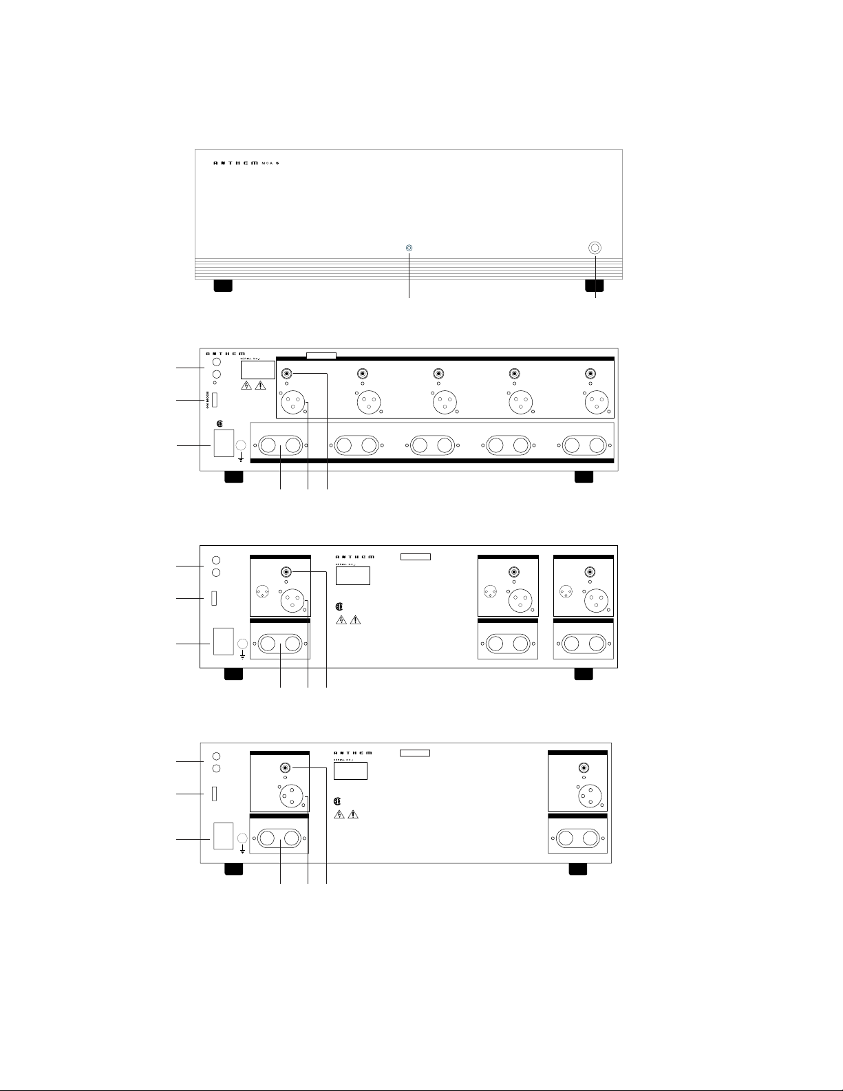
FIGURE 4
MCA 2 Series II rear panel.
LEFT - OUTPUT
LEFT - INPUTS
CENTER - OUTPUT
CENTER - INPUTS
RIGHT - OUTPUT
RIGHT - INPUTS
SINGLE-ENDED
BALANCED
SINGLE-ENDED
BALANCED
SINGLE-ENDED
BALANCED
G
–
+
12
3
G
–
+
12
3
G
–
+
12
3
MANUAL-ON
AUTO-ON
TRIGGER-ON
INPUT
OUTPUT
TRIGGER
5-24V AC/DC
120V ~ 60Hz
1100VA MAXIMUM
+
–
RIGHT CENTER LEFT
+
–
+
–
R C
L
ON MODE
MCA
3
THIS PRODUCT IS BUILT WITH THE
FOLLOWING PATENTS:
5636288, 2142644
WARNING:
SHOCK HAZARD DO NOT OPEN.
AVERTISSEMENT:
RISQUE DE CHOC LECTRIQUE
NE PAS OUVRIR.
NRTL/C
LR 103255
This product has been
certified by CSA.
MCA
2
MANUAL-ON
AUTO-ON
TRIGGER-ON
INPUT
OUTPUT
TRIGGER
5-24V AC/DC
120V ~ 60Hz
800VA MAXIMUM
+
–
RIGHT
LEFT
+
–
R
L
RIGHT - OUTPUT
RIGHT - INPUTS
ON MODE
LEFT - OUTPUT
LEFT - INPUTS
SINGLE-ENDED
BALANCED
SINGLE-ENDED
BALANCED
THIS PRODUCT IS BUILT WITH THE
FOLLOWING PATENTS:
5636288, 2142644
WARNING:
SHOCK HAZARD DO NOT OPEN.
AVERTISSEMENT:
RISQUE DE CHOC LECTRIQUE
NE PAS OUVRIR.
NRTL/C
LR 103255
This product has been
certified by CSA.
A
B
C
D
E
F
G
H
C
D
E
F
G
H
C
D
E
F
G
H
FIGURE 3
MCA 3 Series II rear panel.
FIGURE 2
MCA 5 Series II rear panel.
FIGURE 1
MCA Series II front panel.
Series II
Series II
Series II
Page 4

4 MCA SERIES II AMPLIFIERS
CONTROL FUNCTIONS (SEE FIGURE 1)
A 2-COLOUR LED
In MANUAL mode, the LED is lit “green” when the amplifier is “ON”, receiving power from the power supply. In TRIGGER
or AUTO mode, the LED will be lit “red” until the amplifier receives a music signal (auto) or a trigger voltage (trigger),
at which point it will turn “green”.
B POWER BUTTON
When in the ON position (button depressed), high voltage power is received by the amplifier circuitry from the
power source. When in the OFF position (not depressed), the amp is not receiving power and is not operational.
CONNECTION FUNCTIONS (SEE FIGURES 2 TO 4)
C TRIGGER (INPUT & OUTPUT)
These 3.5mm (.125”) mini-jacks receive (input) a 5-24V AC/DC trigger signal and deliver (output) the same trigger signal
(throughput) from an upstream component (preamplifier, surround sound processor (SSP), system controller etc.).
D ON MODE
With this three way switch, you may select the way in which your amplifier is turned ON/OFF:
• TRIGGER ON:
This feature will allow your amplifier to be turned on or off remotely via the Trigger described above (C).
• AUTO ON:
This innovative feature eliminates the need for a manually operated power switch. AUTO ON simply turns the amplifier
on whenever there is an input signal on any one of the channels. If no input signal is sensed after a period of time, the
amplifier will switch off automatically.
• MANUAL ON:
When in this position, the amplifier can only be turned ON/OFF via the power switch on the front panel (B).
E DETACHABLE AC POWER CORD SOCKET
Plug the Detachable Power Cord into this socket. The MCA Series II Amplifiers are factory built for the correct operating voltage
for the area in which it is sold (see shipping box for voltage setting). If a different operating voltage is required, please
contact an authorized Anthem dealer, distributor or the factory directly to return your unit.
F SPEAKER CONNECTION POSTS
Each custom 5-way binding post accepts a connection from one speaker. The negative/black (–) connection on the
speaker is to be made to the negative/black (–) binding post on the appropriate amplifier channel. As well, the
positive/red (+) connection on the speaker is to be made to the positive/red (+) binding post on the same amplifier
channel. Connect the L, LS, C, RS or R speakers to the appropriate set of binding posts.
Be careful not to overtighten the binding posts.
G BALANCED XLR INPUT
This input accepts balanced XLR input connections from an external preamp or SSP unit.
H SINGLE-ENDED (UNBALANCED) RCA INPUT
This input accepts unbalanced RCA input connections from an external preamp or SSP unit.
Page 5

MCA SERIES II AMPLIFIERS 5
OPERATION
Before plugging in the MCA Series II Amplifier, check to see
that the unit is configured for the correct AC line voltage for
country of use. The operating AC line voltage is indicated on
the side of the shipping box. If the amplifier is set incorrectly
for the country in which it is to be operated, contact the
dealer or distributor in your area. If the unit is configured
properly, continue with operation.
Connect the Detachable Power Cord to the AC Power Cord
Socket (E). Plug your amplifier into the AC power source.
Connect loudspeakers to the appropriate post as described
in the Speaker Connection Posts section above.
The remaining input signal connection is made with either
Balanced (XLR) or Unbalanced (RCA) connectors from a
suitable Preamp or SSP such as the Anthem AVM 2.
Connect the preamp/SSP outputs to the appropriate amplifier
inputs (G or H) for each channel. If available, the XLR
balanced inputs are preferred. Regardless, choose one or
the other input formats per channel.
Note: If both types of inputs are connected simultaneously
(per channel), the MCA Series II Amplifiers will automatically default to the RCA unbalanced input format bypassing
the XLR balanced input.
Select an appropriate ON MODE for your MCA Series II
Amplifier. If TRIGGER mode is selected connect a trigger cable
between your MCA Series II Amplifier and the upstream control
component.
After you ensure your preamp or SSP has the volume
turned down or muted, you can power up your MCA Series II
Amplifier, which is now ready for operation.
BREAK-IN TIME
As with all audio electronic products, the ultimate sonic
character of the MCA Series II Amplifiers will not be realized
until and unless the unit receives a minimum of approximately
70 hours of signal break-in time (i.e. the amplifier is on and
outputting a signal).
PLACEMENT FOR PROPER VENTILATION
The MCA Series II Amplifiers require a minimum of 12”
(30cm) above, of unobstructed air space. Make sure that
the ventilation slots on the top and bottom remain unobstructed by any object. Do not stack any other component
on top of the amplifier or block the ventilation slots in any
way. Also, be sure that the amplifier is placed on a secure,
hard and level surface, NOT on carpet.
In the event of overheating, your MCA Series II Amplifier
is equipped with a thermal shut off feature. The amplifier
will remain off until the temperature falls below the shut
off threshold. Once this condition is met, the amplifier will
reset itself and it can be powered on again.
PACKING MATERIALS
Please retain all of the packing material and shipping boxes for
your MCA Series II Amplifier. They are custom designed to
prevent shipping damage from occurring. Sonic Frontiers Int’l
will accept no responsibility for any damage occurring to an
MCA Series II Amplifier that is shipped in packing material
other than the original Sonic Frontiers packing material.
DISCLAIMER OF LIABILITY
Under no circumstances does Sonic Frontiers Int’l assume
liability or responsibility for injury or damages sustained in
the use or operation of this equipment or for damages to any
other equipment connected to it.
Sonic Frontiers Int’l reserves the right to make design
changes or improvements without the obligation to revise
prior versions. All specifications are subject to change
without notice.
TROUBLESHOOTING
If at any time the MCA Series II Amplifier fails to work properly,
consult this checklist:
1. Check that the AC Detachable Power Cord is plugged into
the Detachable Power Cord Socket (E) and is connected to a
live source of AC power. For instance, if using a power bar,
check that the bar is turned on.
2. Ensure that all Input and Output connections are secure for
a proper electrical contact.
3. Ensure that the amplifier is configured for the appropriate
ON MODE in your system setup.
If a problem still persists, please contact your authorized Anthem
Dealer or the Factory directly.
Page 6

6 MCA SERIES II AMPLIFIERS
TECHNICAL SPECIFICATIONS
INPUTS MCA 2 Series II 2 Balanced, 2 Single-ended, 1 Relay Trigger (3.5mm Stereo Jack)
MCA 3 Series II 3 Balanced, 3 Single-ended, 1 Relay Trigger (3.5mm Stereo Jack)
MCA 5 Series II 5 Balanced, 5 Single-ended, 1 Relay Trigger (3.5mm Stereo Jack)
OUTPUTS MCA 2 Series II 2 Pairs Speaker Binding Posts, 1 Relay Trigger (3.5mm Stereo Jack)
MCA 3 Series II 3 Pairs Speaker Binding Posts, 1 Relay Trigger (3.5mm Stereo Jack)
MCA 5 Series II 5 Pairs Speaker Binding Posts, 1 Relay Trigger (3.5mm Stereo Jack)
SWITCHES (2) Power On/Off, 3 Way On Mode (Auto-on, Manual-on, Trigger-on)
DIMENSIONS MCA 2 Series II 17.25" (44 cm) W x 5.25" (13.5 cm) H x 12” (30.5 cm) D
MCA 3 Series II 17.25" (44 cm) W x 5.25" (13.5 cm) H x 12” (30.5 cm) D
MCA 5 Series II 17.25" (44 cm) W x 5.25" (13.5 cm) H x 17” (43 cm) D
NET WEIGHT MCA 2 Series II 36 Ibs, (16 kg)
(Unpacked)
MCA 3 Series II 42 Ibs, (19 kg)
MCA 5 Series II 56 Ibs, (25.5 kg)
POWER OUTPUT Impedance:
8Ω 4Ω 2Ω
(Continuous, RMS, # of Channels Driven:
1 All 1 All 1 All
20Hz - 20kHz, <1.0% THD,
MCA 2 Series II 200 W 185 W 350 W 270 W 500 W 400 W
AC line voltage held
MCA 3 Series II 200 W 170 W 350 W 250 W 500 W 320 W
constant at full load) MCA 5 Series II 200 W 170 W 350 W 250 W 500 W 320 W
HEADROOM 267W (8Ω); 479W (4Ω)
POWER BANDWIDTH 10Hz - 80kHz (-3dB)
FREQUENCY RESPONSE 0.5Hz - 20kHz (-0.15dB), 0.5Hz - 80kHz (-2dB)
THD&N 0.03%, 20Hz - 20kHz at half power into 8Ω
0.0015%, 1kHz at half power into 8Ω
INPUT SENSITIVITY 1.35VRMS for 200 Watts into 8Ω
INPUT IMPEDANCE 21kΩ (RCA), 15kΩ (XLR)
DAMPING FACTOR 130 @ 8Ω
HUM & NOISE -122dBW, A-Weighted @ 200W
VOLTAGE GAIN 29dB
SLEW RATE 20V/µs
POWER REQUIREMENTS MCA 2 Series II 800VA
MCA 3 Series II 1100VA
MCA 5 Series II 1800VA
All tests were performed with the Audio Precision System Two @ 120VAC.
Page 7

MCA SERIES II AMPLIFIERS 7
LIMITED FIVE YEAR WARRANTY
Sonic Frontiers International warrants to the purchaser that
each component is free of manufacturing defects for a period
of five (5) years from the date of purchase. This five (5) year
limited warranty excludes all vacuum tubes and CD
Transport mechanisms, which are warranted for a period of
twelve (12) months. To receive this warranty, the original
purchaser must complete and mail to Sonic Frontiers
International, within thirty (30) days from the date of
purchase, the enclosed Warranty Registration Card which
validates the warranty. This warranty is subject to the
following conditions and limitations:
DISCLAIMER OF LIABILITY
Under no circumstances does Sonic Frontiers International
assume liability or responsibility for injury or damages
sustained in the use or operation of this equipment or for
damages to any other equipment connected to it. Sonic
Frontiers International reserves the right to make design
changes or improvements without the obligation to revise
prior versions. All specifications are subject to change
without notice.
Warranty applies only to the original purchaser and is
non-transferable.
This warranty is void and inapplicable if the product has been
handled other than in accordance with the instructions of our
Owner's Manual, abuse or misused, damaged by accident
or neglect or in being transported, or the defect is due to the
product being tampered with, modified or repaired by
anyone other than Sonic Frontiers International, or an
authorized Sonic Frontiers International repair service center.
Warranty does not cover normal maintenance.
Sonic Frontiers International shall not be responsible in any
way for consequential or indirect damages or liabilities resulting from the use and operation of the product covered
herein or resulting from any breach of this warranty or any
implied warranty relating to said product.
During this period, Sonic Frontiers International will repair or
replace any defective components free of charge. If a problem
or defect is discovered in your product, please contact the
dealer or distributor from which it was purchased. It is the
responsibility of the dealer/distributor to determine the
nature of the problem and arrange for either the appropriate
replacement parts or, the return of the product to the factory.
All other warranties or conditions either written or implied
are void.
Sonic Frontiers International reserves the right to improve
the design of any product without assuming any obligation
to modify any product previously manufactured. This warranty
is in lieu of all other warranties expressed or implied, of
merchantability, fitness for any particular purpose and may
not be extended or enlarged by anyone. In no event shall
Sonic Frontiers International, their agents or representatives
be responsible for any incidental or consequential damages.
Some jurisdictions do not allow limitations of incidental or
consequential damages, so this exclusion may not apply to you.
INTERNATIONAL WARRANTY
Outside of Canada and the USA, SFI sells to exclusive
distributors who are responsible for the service and support
of our equipment. Your warranty in these countries are
provided by the local distributor, not SFI. Sonic Frontiers will
provide parts to the original purchaser of our components via
the distributor, for 5 years on electronics and one year on CD
mechanisms and vacuum tubes. All repairs and labor charges
in international markets are the responsibility of the distributor.
Units returned to SFI for repair at our factory in Oakville must
have an accompanying original bill of sale from an authorized
retailer to receive our warranty service. Under warranty, SFI
will provide parts and labor to the original purchaser but will
not cover freight or duties to or from, our factory. A Return
Authorization number must be obtained in advance by calling
1-905-829-3838. All other repairs will be at our regular
bench rates for labor plus parts cost.
WARRANTY (USA & CANADA)
FREQUENTLY ASKED WARRANTY QUESTIONS
WHAT IS THE FLOOR MODEL WARRANTY?
Display equipment sold by an authorized dealer has a full
5 year Parts & Labor and 30 day Tube & Transport
Mechanism warranty (as of the date of the customers
invoice) or the balance of the 1 year Tube & Transport
Mechanism warranty (as of the date of the dealer
invoice) - which ever is longer.
WHAT IS THE USED EQUIPMENT WARRANTY?
The balance of the 5 year Parts & Labor and 1 year Tube
& Transport Mechanism warranty can be transferred on
used equipment only if the unit is traded in to an authorized
Sonic Frontiers/Anthem Dealer. An authorized SF/
Anthem dealer can resell the unit with the remaining
warranty if it is cosmetically acceptable, in perfect working
condition, and has not been internally or externally
altered in any way. We ask that the dealers call the
factory and advise us of the serial number of the unit to
register the warranty of the new owner.
WHAT IS THE USED EQUIPMENT WARRANTY - FROM A
NON-AUTHORIZED DEALER?
Used equipment purchased from a non-authorized dealer
or private sale has no SFI warranty.
PLEASE READ CAREFULLY!
Page 8

DESIGNED AND MANUFACTURED BY SONIC FRONTIERS INTERNATIONAL
3535 LAIRD ROAD, UNIT #16, MISSISSAUGA, ONTARIO, CANADA L5L 5Y7 TEL: (905) 828-4575 FAX: (905) 828-4585
Sonic Frontiers can be reached 9:00 am to 5:00 pm (E.S.T.) or 24 hours a day by facsimile
E-MAIL: SFI@sonicfrontiers.com WEB SITE: http//www.sonicfrontiers.com
05/02/02
 Loading...