

Page 1

INTEGRATED 225
OPERATING MANUAL
w w w . a n t h e m A V . c o m
™
Page 2

SAFETY PRECAUTIONS
READ THIS SECTION CAREFULLY BEFORE PROCEEDING!
WARNING
RISK OF ELECTRIC SHOCK
DO NOT OPEN
WARNING: TO REDUCE THE RISK OF ELECTRIC
SHOCK, DO NOT REMOVE COVER (OR BACK).
NO USER-SERVICEABLE PARTS INSIDE. REFER
SERVICING TO QUALIFIED SERVICE PERSONNEL.
The lightning flash with arrowpoint within an equilateral triangle
warns of the presence of uninsulated “dangerous voltage”
within the product’s enclosure that may be of sufficient
magnitude to constitute a risk of electric shock to persons.
The exclamation point within an equilateral triangle warns users
of the presence of important operating and maintenance
(servicing) instructions in the literature accompanying the appliance.
WARNING: TO REDUCE THE RISK OF FIRE OR ELECTRIC SHOCK, DO NOT EXPOSE THIS PRODUCT TO RAIN OR MOISTURE
AND OBJECTS FILLED WITH LIQUIDS, SUCH AS VASES, SHOULD NOT BE PLACED ON THIS PRODUCT.
CAUTION: TO PREVENT ELECTRIC SHOCK, MATCH WIDE BLADE OF PLUG TO WIDE SLOT, FULLY INSERT.
CAUTION: FOR CONTINUED PROTECTION AGAINST RISK OF FIRE, REPLACE THE FUSE ONLY WITH THE SAME AMPERAGE
AND VOLTAGE TYPE. REFER REPLACEMENT TO QUALIFIED SERVICE PERSONNEL.
WARNING: UNIT MAY BECOME HOT. ALWAYS PROVIDE ADEQUATE VENTILATION TO ALLOW FOR COOLING. DO NOT
PLACE NEAR A HEAT SOURCE, OR IN SPACES THAT CAN RESTRICT VENTILATION.
IMPORTANT SAFETY INSTRUCTIONS
1. Read Instructions – All the safety and operating instructions should be read before the product is operated.
2. Retain Instructions – The safety and operating instructions should be retained for future reference.
3. Heed Warnings – All warnings on the product and in the operating instructions should be adhered to.
4. Follow Instructions – All operating and use instructions should be followed.
5. Cleaning – Unplug this product from the wall outlet before cleaning. Do not use liquid cleaners or aerosol cleaners. Use
a damp, soft cloth for cleaning.
6. Water and Moisture – Do not use this product near water – for example, near a bath tub, wash bowl, kitchen sink, or
laundry tub; in a wet basement; or near a swimming pool; and the like.
7. Accessories – Do not place this product on an unstable cart, stand, tripod, bracket, or table. The product may fall,
causing serious injury to a child or adult, and serious damage to the product. Use only with a cart, stand, tripod, bracket,
or table recommended by the manufacturer, or sold with the product. Any mounting of the product should follow
manufacturer’s instructions, and should use a mounting accessory recommended by the manufacturer.
Page 3

8. Ventilation – Slots and openings in the cabinet are provided for ventilation and to ensure reliable operation of the
Antenna Lead-In Wire
Antenna-Discharge Unit
(NEC Section 810-20)
Grounding Conductors
(NEC Section 810-21)
Power Service Grounding
Electronic System
(NEC ART 250. Part H)
NEC-National Electrical Code
Electrical Service
Equiptment
Ground Clamp
Ground Clamps
S2898A
product and to protect it from overheating, and these openings must not be blocked or covered. The openings should
never be blocked by placing the product on a bed, sofa, rug, or other similar surface. This product should not be placed
in a built-in installation such as a bookcase or rack unless proper ventilation is provided or the manufacturer’s
instructions have been adhered to.
9. Power Sources – This product should be operated only from the type of power source indicated on the marking label.
If you are not sure of the type of power supply to your home, consult your product dealer or local power company. For
products intended to operate from battery power, or other sources, refer to the operating instructions.
10. Grounding and Polarization – This product may be equipped with a polarized alternating-current line plug (a plug having
one blade wider than the other). This plug will fit into the power outlet only one way. This is a safety feature. If you are
unable to insert the plug fully into the outlet, try reversing the plug. If the plug should still fail to fit, contact your
electrician to replace your obsolete outlet. Do not defeat the safety purpose of the polarized plug.
11. Power-cord Protection – Power-supply cords should be routed so that they are not likely to be walked on or pinched
by items placed upon or against them, paying particular attention to cords at plugs, convenience receptacles, and the
point where they exit from the product.
12. Outdoor Antenna Grounding – If an outside antenna or cable system is connected to the product, be sure the antenna
or cable system is grounded so as to provide some protection against voltage surges and built-up static charges. Article
810 of the National Electrical Code, ANSI/NFPA 70, provides information with regard to the proper grounding of the mast
and supporting structure, grounding of the lead-in wire to an antenna-discharge unit, size of grounding conductors,
location of antenna-discharge unit, connection to grounding electrodes, and requirements for the grounding electrode.
13. Lightning – For added protection for this product during a lightning storm, or when it is left unattended and unused for
long periods of time, unplug it from the wall outlet and disconnect the antenna or cable systems. This will prevent
damage to the product due to lightning and power-line surges.
14. Power Lines – An outside antenna system should not be located in the vicinity of overhead power lines or other electric
light or power circuits, or where it can fall into such power lines or circuits. When installing an outside antenna system,
extreme care should be taken to keep from touching such power lines or circuits as contact with them might be fatal.
15. Overloading – Do not overload wall outlets, extension cords, or integral convenience receptacles as this can result in
a risk of fire or electric shock.
Page 4

16. Object and Liquid Entry – Never push objects of any kind through openings as they may touch dangerous voltage points
or short-out parts that could result in a fire or electric shock. Do not expose this product to dripping or splashing and
ensure that no objects filled with liquids, such as vases, are placed on the product.
17. Servicing – Do not attempt to service this product yourself, as opening or removing covers may expose you to
dangerous voltage or other hazards. Refer all servicing to qualified service personnel.
18. Damage Requiring Service – Unplug this product from the wall outlet and refer servicing to qualified personnel under
the following conditions:
• When power-supply cord or plug is damaged.
• If liquid has been spilled, or objects have fallen into the product.
• If the product has been exposed to rain or water.
• If the product does not operate normally by following the operating instructions. Adjust only those controls that are
covered by the operating instructions as an improper adjustment of other controls may result in damage and will require
extensive work by a qualified technician to restore the product to its normal operation.
• If the product has been dropped or damaged in any way.
• If the product exhibits a distinct change in performance – this indicates a need for service.
19. Replacement Parts – When replacement parts are required, be sure the technician has used replacement parts
specified by the manufacturer or have the same characteristics as the original part. Unauthorized substitutions may
result in fire, electric shock, or other hazards.
20. Safety Check – Upon completion of any service or repairs to this product, ask the service technician to perform safety
checks to determine that the product is in proper operating condition.
21. Heat – The product should be situated away from heat sources such as radiators, heat registers, stoves, or other
products (including amplifiers) that produce heat.
RECYCLING AND REUSE GUIDELINES (Europe)
In accordance with the European Union WEEE (Waste Electrical and Electronic Equipment) directive effective
August 13, 2005, we would like to notify you that this product may contain regulated materials which, upon disposal,
require special reuse and recycling processing. For this reason Paradigm Electronics Inc. (the manufacturer of
Paradigm speakers and Anthem electronic products) has arranged with its distributors in European Union member
nations to collect and recycle this product at no cost to you. To find your local distributor please contact the dealer
from whom you purchased this product or go to our website at www.paradigm.com.
Please note that only the product falls under the WEEE directive. When disposing of packaging and other shipping
material we encourage you to recycle through the normal channels.
Anthem, Sonic Frontiers, and Paradigm are trademarks or registered trademarks of Paradigm Electronics Inc.
Copyright Paradigm Electronics Inc. All rights reserved. The information contained herein may not be reproduced in whole
or in part without our express written permission. We reserve the right to change specifications and/or features without
notice as design improvements are incorporated.
Page 5

1. INTRODUCTION
Thank you for purchasing the Anthem Integrated 225.
The I225 is an integrated preamplifier and amplifier. Anthem products are engineered to recreate the passion
of live performance and thrill of the best movie theaters by using the highest level of circuit design, superior
build quality, innovative features, and intuitive ergonomics.
1.1 BEFORE MAKING CONNECTIONS
Check that you have received everything listed below and report discrepancies to your dealer as soon as
possible. Retain all packing materials and use them for any future shipment.
Packing List:
• Integrated 225 • 2 AA Batteries • Power cord (North America only)
• Remote control • Operating manual
Keep the invoice that you received from your authorized Anthem dealer at time of purchase – without
it, service will not be provided under warranty.
Safety Instructions:
• Read all precautions and instructions at the beginning of this manual.
• Do not connect power if there are signs of damage to any part of the exterior.
• The Front Panel power button does not disconnect the product from the AC line. Ensure that the
power cord remains readily accessible at all times.
• Use only the supplied power cord to connect power.
• Allow adequate ventilation to ensure reliable operation and to prevent overheating. The amount of
space required above the unit for radiation depends on ambient air temperature and circulation.
Installation inside an unventilated space such as a cabinet with a front that can be closed or a
closet is not recommended.
• Failing to comply with any safety instruction, precaution, or warning in this Operating Manual is in
violation of the intended use of the product.
• Anthem and any related party assume no liability for the user’s failure to comply with requirements.
1.2 IN-USE NOTICES
• Disconnect the power cord before connecting or disconnecting any components.
• Do not remove the top cover.
• Do not modify the product.
1
Page 6

1. INTRODUCTION continued …
POWER
PHONO CD BA LANCED
RECOR DER
MUTE
BASSTONE DE FEAT TREBL E BALAN CE
AUX 1 AUX 2 AUX 3
IN T EG RA TE D 2 25
AUX 4
1.3 FRONT PANEL
1011 9 8 7 6 5 4 3 2
1
1 – Volume Control
2 – Power On / Standby
3 – Mute
4 – Balance
5 – Treble
6 – Bass
7 – Tone Defeat
8 – Remote Control Sensor
9 – Stereo Mini Input Jack and Selector – for use with a portable audio device
10 – Headphone Jack
11 – Source Selection
For a larger diagram, see inside back cover.
2
Page 7
BALANCED I NPUT
RS-232 CON TROL
12 V
TRIGGER
IN OUT IN O UT
I.R.
RECEIVER
PHONO
GND
PHONO CD AUX 1
OUTPUTS
SPEAKER OU TPUTS
AUX 2 AUX 3 RECORDER RE C
OUT
PRE
OUT
R+ - L- +
L
R
INPUTS
RISKOF ELECTRIC SHOCK –DO NOT OPEN
RISQUEDE CHOC ELECTRIQUE– NE PAS OUVRIR
FUSE T12A/ 250V
AC 1 20V/60Hz
POWER CONS UMPTION: 30 0W TYPICAL
CAUTION| TO PR EVENT ELECTRI C SHOCK, DO NOT REMOV E
TOP COVER . NO USER-SE RVICEABLE PARTS INSIDE, REFER
SERVICING TO QUALI FIED SERVICE PERSONNEL.
WARNING | TO PREVENT FIR E OR SHOCK HAZARD, DO NOT
EXPOSE THIS UNIT TO RAIN OR MOISTURE .
L
R
L
R
IN T EG RA TE D 22 5
DESIGNED AND ENGINEERED BY
SONIC FRONTIERS INTERNATIONAL
MADE IN TAIWAN
1. INTRODUCTION continued …
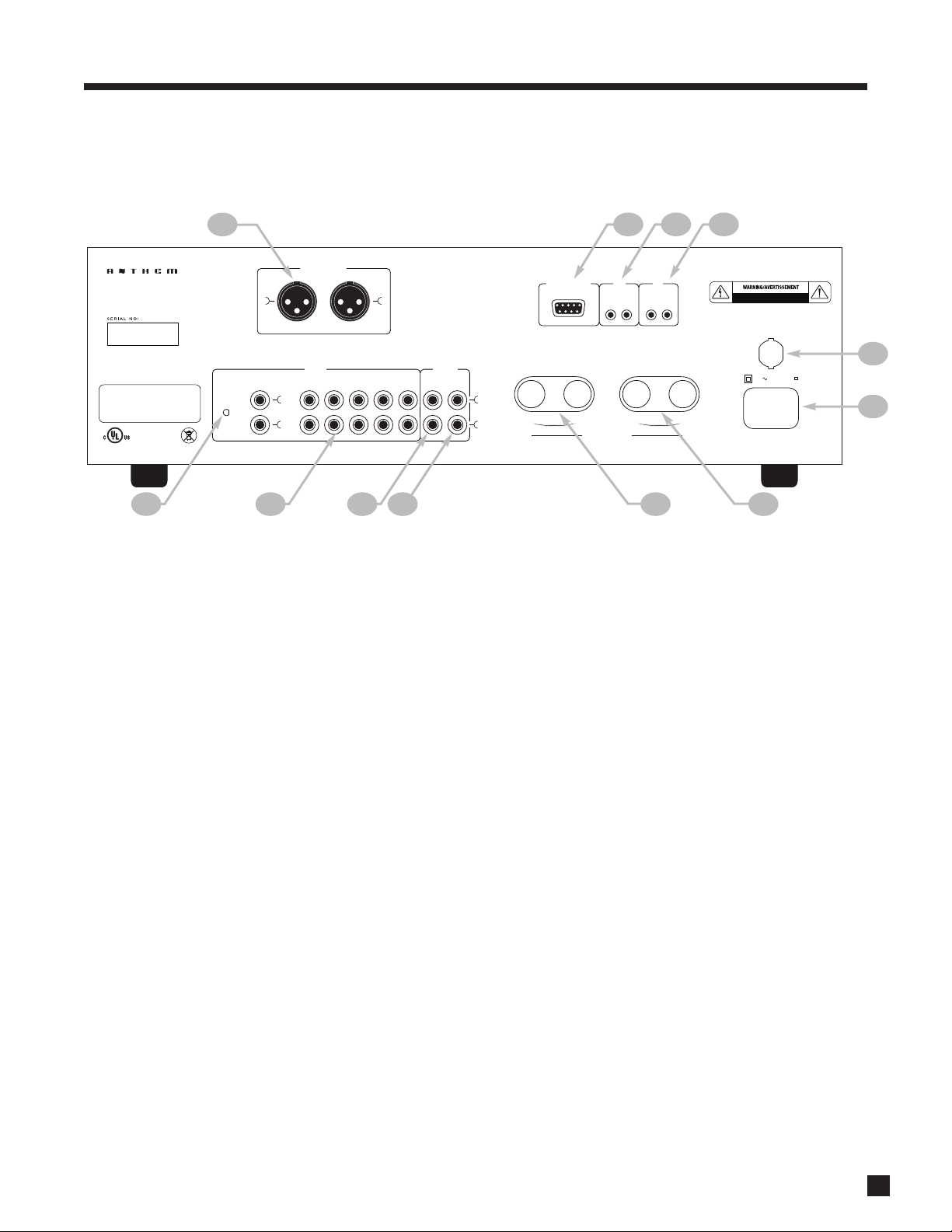
1.4 REAR PANEL
1
12
11 10 9
1 – XLR (balanced) input – connect if using source with balanced output
2 – RS-232 interface – for use with custom control systems
3 – 12 Volt trigger in / out
4 – I.R. receiver in / out
5 – Fuse
6 – Power cord connection
7 – Left speaker output
8 – Right speaker output
9 – Preamplifier (volume-controlled) output – connect if using external amplifier
10 – Record (line level) output
11 – 5 RCA inputs
12 – Phono input with ground connection
2
3
4
5
6
78
For a larger diagram, see inside back cover.
3
Page 8

1. INTRODUCTION continued …
1.5 REMOTE CONTROL
1 2
1 – Power OFF
2 – IR Transmitter (front face)
3 – LED
4 – Power ON
5 – Set (for customization of remote)
6 – Control mode (to control other components)
7 – Volume
8 – Tone Enable / Bypass
9 – Mute
10 – Source
The remaining keys are for custom setup to control other equipment.
When a key is pressed, the keys light with amber color.
Rear: Battery cover – low battery power is indicated by LED double
blink and no backlight
3
4
5
6
7
8
9
10
4
Page 9

1. INTRODUCTION continued …
1.6 INTERCONNECTS
These illustrations show audio, IR, and trigger connectors used between source components and the I225.
1/4” Stereo
Headphone
3.5mm
Mini (Mono)
12V Trigger
IR Emitter
3.5mm
Mini (stereo)
Digital Audio
RCA Black or
White
Analog Left
Channel
RCA Red
Analog Right
Channel
XLR Female
(connects to output)
Analog Balanced or AES/EBU
(connects to input)
XLR Male
5
Page 10

2. CONNECTIONS
2.1 INPUT CONNECTIONS
Connect source components and recorder according to the diagrams in the following pages. If using a
turntable, connect it to PHONO input only. If the turntable is equipped with a ground wire, connect it to the
ground terminal next to the PHONO input by unscrewing the terminal then inserting wire and tightening the
screw terminal onto the wire.
use ‘RCA-compatible’ connectors that have a hollow center pin with a hole at the tip – inserting
Do not
them into the Integrated 225’s RCA jacks can cause internal damage.
2.2 SPEAKER CONNECTIONS
Depending on the level of the input signal and volume setting, the voltage at the outputs can be high enough
to cause electric shock – be sure that power is turned off when connecting or disconnecting anything.
Ensure that the speakers are rated for use with this amplifier – an overdriven speaker can pose a fire hazard.
Connect the red (+) connection on the speaker to the red (+) binding post on the appropriate amplifier
channel, and the black (–) connection on the speaker to the black (–) binding post on the same amplifier
channel, using cable that is insulated to handle the maximum output of the amplifier. Do not overtighten the
binding posts as this may cause damage. Each binding post accepts a connection from one speaker.
2.3 TRIGGER
This feature allows the amplifier to be turned on or off remotely via the trigger. The 3.5mm (.125”) mini-jack
INPUT receives a 12V signal from an upstream component or system controller. The same trigger signal can
be linked to other components through the OUTPUT.
2.4 I.R. (INFRA RED) RECEIVER
External IR receivers allow the Remote Control to be used from other locations in your home. Once an IR
receiver is wired to another room, connect it to I.R. RECEIVER IN. The signal can be linked to other
components through I.R. RECEIVER OUT.
2.5 POWER
After the system is connected use the supplied power cord to connect power. It is normal for a ‘click’ to be
heard from inside the chassis when connecting power.
6
Page 11

2. CONNECTIONS continued …
BALANCED I NPUT
RS-232 CON TROL
12 V
TRIGGER
IN OUT IN OU T
I.R.
RECEIVER
PHONO
GND
PHONO CD AUX 1
OUTPUTS
SPEAKER OU TPUTS
AUX 2 AUX 3 RECORDER REC
OUT
PRE
OUT
R+- L-+
L
R
INPUTS
RISKOF ELECTRIC SHOCK– DO NOT OPEN
RISQUEDE CHOC ELECTRIQUE– NE PAS OUVRIR
FUSE T12A/ 250V
AC 1 20V/60Hz
POWER CONS UMPTION: 300 W TYPICAL
CAUTION| TO PR EVENT ELECTRI C SHOCK, DO NOT REMOV E
TOP COVER . NO USER-SE RVICEABLE PARTS INSIDE, REFER
SERVICING TO QUALI FIED SERVICE PERSONNEL.
WARNING | TO PREVENT FIR E OR SHOCK HAZARD, DO NOT
EXPOSE THIS UNIT TO RAIN OR MOISTURE .
L
R
L
R
IN T EG RA TE D 22 5
DESIGNED AND ENGINEERED BY
SONIC FRONTIERS INTERNATIONAL
MADE IN TAIWAN
Example 1: CD Player to Integrated 225
AUDIO OUT
LR
7
Page 12

2. CONNECTIONS continued …
BALANCED I NPUT
RS-232 CON TROL
12 V
TRIGGER
IN OUT IN OU T
I.R.
RECEIVER
PHONO
GND
PHONO CD AUX 1
OUTPUTS
SPEAKER OU TPUTS
AUX 2 AUX 3 RECORDER REC
OUT
PRE
OUT
R+- L-+
L
R
INPUTS
RISKOF ELECTRIC SHOCK– DO NOT OPEN
RISQUEDE CHOC ELECTRIQUE– NE PAS OUVRIR
FUSE T12A/ 250V
AC 1 20V/60Hz
POWER CONS UMPTION: 300 W TYPICAL
CAUTION| TO PR EVENT ELECTRI C SHOCK, DO NOT REMOV E
TOP COVER . NO USER-SE RVICEABLE PARTS INSIDE, REFER
SERVICING TO QUALI FIED SERVICE PERSONNEL.
WARNING | TO PREVENT FIR E OR SHOCK HAZARD, DO NOT
EXPOSE THIS UNIT TO RAIN OR MOISTURE .
L
R
L
R
IN T EG RA TE D 22 5
DESIGNED AND ENGINEERED BY
SONIC FRONTIERS INTERNATIONAL
MADE IN TAIWAN
Example 2: Recorder to Integrated 225
AUDIO OUT
LR
AUDIO IN
LR
8
Page 13

3. OPERATION
POWER
MUTE
PHONO CD BA LANCED
RECOR DER
AUX 1 AUX 2 AUX 3
AUX 4
3.1 POWER ON/OFF
Power on is indicated when the LED above the from panel power button is lit.
Front panel – power ON/OFF
• Press POWER in the lower left of the front panel.
Remote control – power ON
• Make sure that INT control mode is set then press the power key
in the upper left.
Remote control – power OFF
• Make sure that INT control mode is set then press the power OFF
key in the upper right.
3.2 SOURCE SELECTION
Select a source by pressing one of the following buttons – make sure that INT control mode is set if using
remote control:
When RECORDER is selected, the REC output is disabled since a recorder cannot record itself.
3.3 VOLUME CONTROL
Front panel:
• Rotate the volume knob clockwise to increase the volume and counterclockwise to
decrease the volume.
Remote control:
• Make sure that INT control mode is set then use the VOL+and VOL keys.
Mute:
When MUTE is pressed, the audio is silenced and the front panel indicator above the
button flashes. Press MUTE again and sound will return.
9
Page 14

3. OPERATION continued …
BASSTONE DE FEAT TREBL E
BALAN CE
3.4 BALANCE CONTROL
If the center of the soundstage is off-center, rotate the balance control in the direction that the
soundstage needs to be moved. The center position is the default.
3.5 TONE CONTROL
To adjust the bass and/or treble level, rotate the Bass and Treble
knobs on the front panel. The center position is the default. If an
adjustment is made, you can press TONE on the front panel or remote
to quickly turn the adjustment on/off without having to return the
knobs to the center position – the indicator above the button lights when the controls are defeated.
It is normal for a ‘click’ to be heard from the chassis when pressing Power, Mute, or a source button.
10
Page 15

4. REMOTE CONTROL CUSTOMIZATION
4.1 CODES FOR OTHER BRANDS
The Integrated 225 remote can control other components – a list of brands and setup instructions are at the
end of this section. If the brand for your component is not listed, try searching for a code as follows:
1. Turn on the component, for example the DVD player.
2. Press a control mode key other than
3. Press and hold SET until the LED flashes twice then press 9, 9, 1.
4. Press 0 for cable converters, satellite receivers, or video accessories, 1 for TVs, 2 for DVD players
or VCRs, or 3 for CD players or audio amps/tuners.
5. Aim the remote towards the player and press POWER (or Play). If the player does not respond, press
CH+to try the next code. If the player responds, press SET to lock the code. Codes are sent in order
of popularity. CH goes to the previous code. If no code is found, see section 4.2.
6. After finding a code, record it: Press and hold SET until the LED flashes twice, then press 9, 9, 0, 1.
Wait 3 seconds and count the number times that the LED flashes. This represents the first digit (for
example, 3 flashes = 3, no flash = 0) – write this down. Next, press 2 for the second digit, 3 for the
third digit, 4 for the fourth digit, 5 for the fifth digit and write the number of flashes each time.
4.2 LEARNING COMMANDS
Commands from almost any other infra-red remote control can be captured by the Integrated 225 remote
control. The factory command is still available by pressing SET before pressing the taught key.
If the factory command is used more than the learned command, the learned command can be programmed
in Layer2 instead. In this case, the learned command is sent by pressing SET before pressing the key.
Before teaching a key note the following:
• Control mode keys and SET can not be taught. These keys never send IR commands
INT, for example DVD.
.
• A multiple key sequence (for example Rec+Pause or Rec+Play) can not be taught to one key.
• A high level of ambient light, light from displays, and exposed fans could interfere with learning.
To teach a key:
1. Point the source and Integrated 225 remotes at each other, holding them approximately 2 inches apart.
2. Press and hold SET until the LED flashes twice then press 9, 7, 5. One long blink indicates low
battery or faulty memory – the remote will not go into learn mode under either of these conditions.
3. Press the desired control mode key.
4. Press the key to be taught, or to program the command into Layer2 press SET (don’t hold) and then
press the key to be taught.
5. The LED flashes rapidly. Within 4 seconds, press and hold the teaching key on the source remote
until the LED flashes twice. One long blink means bad capture (try again), memory full (delete
another command), or unlearnable code.
6. Repeat steps 3-5 or 4-5 as often as desired until memory is full.
7. To exit, press and hold SET until the LED flashes twice or wait 10 seconds.
Deleting learned commands:
1. Press and hold SET until the LED flashes twice, then press 9, 7, 6.
2. To delete a learned command from one key, press the control mode key, then the key to be deleted
twice. To delete all learned commands in the control mode, press the control mode key twice.
11
Page 16

4. REMOTE CONTROL CUSTOMIZATION continued …
4.3 COPYING COMMANDS
The command from one key can be copied to another key (not applicable to Power, Record, and Set keys).
To copy a command to another key in the same control mode:
1. Press the control mode key.
2. Press and hold SET until the LED flashes twice.
3. Press 9, 9, 4.
4. Press the key to be copied.
5. Press the new key that will have the command. The LED flashes twice.
To copy a command into a different control mode:
1. Press and hold SET until the LED flashes twice.
2. Press 9, 9, 4.
3. Press the control mode key of the key to be copied then the key to be copied.
4. Pressthe new control mode key thenthe new keythat will have the command. The LEDflashes twice.
To set the original functions:
1. Press the control mode key.
2. Press and hold SET until the LED flashes twice.
3. Press 9, 9, 4.
4. Press the control mode key twice.
4.4 VOLUME LOCK
With Volume Lock engaged, the volume and mute keys control the Integrated 225 regardless of control mode,
making operation more convenient.
To engage Volume Lock for MAIN:
1. Press and hold SET until the LED flashes twice.
2. Press 9, 9, 3.
3. Press MAIN.
To dis-engage Volume Lock for TV and re-engage the TV’s volume control:
1. Press ZONE2 (or ZONE3).
2. Press and hold SET until the LED flashes twice.
3. Press 9, 9, 3.
12
4. Press VOL .
The Volume and Mute keys now control the Integrated 225 for every control mode selection except TV. You
may continue to disengage other control modes one at a time. To disengage all, press VOL+in step 4.
Page 17

4. REMOTE CONTROL CUSTOMIZATION continued …
4.5 PROGRAMMING MACROS
Macros are used to execute multiple functions with one key press, such as powering the Integrated 225,
cable box, and display On at the same time. Up to 32 commands can be programmed.
Programming a Macro that works regardless of control mode setting:
1. Press and hold SET until the LED flashes twice.
2. Press 9, 9, 5.
3. Press the key you want to use to activate your macro (e.g. Power).
4. Enter the command sequence that you want the macro to execute.
5. To exit, press and hold SET until the LED flashes twice or wait 10 seconds.
To clear the macro, repeat the steps above but skip step 4.
Programming a Macro that works in one control mode:
1. Press the control mode key.
2. Press and hold SET until the LED flashes twice.
3. Press 9, 7, 8.
4. Press the key you want to use to activate your macro (e.g. Power).
5. Enter the command sequence that you want the macro to execute.
6. To exit, press and hold SET until the LED flashes twice or wait 10 seconds.
To clear the macro:
1. Press and hold SET until the LED flashes twice, then release.
2. Press 9, 7, 8.
3. Press the control mode key where you programmed the macro.
4. Press the key that was programmed to activate the macro.
5. To exit, press and hold SET until the LED flashes twice or wait 10 seconds.
13
Page 18

4. REMOTE CONTROL CUSTOMIZATION continued …
The following codes are for setting operation of other components with the Integrated 225 remote control. If codes for
your components are not in this library, see sections 4.1 and 4.2.
To enter a 5-digit code:
1. Press the control mode key near the top of the remote (e.g. CD).
2. Press and hold SET until the LED flashes twice.
3. Enter the 5-digit code. Two LED blinks indicate that the code is accepted.
14
CD Players:
Acoustic Research 30420
Admiral 30305
Aiwa 30157
Arcam 30157
Audio Research 30157
Burmester 30420
Cairn 30157
California Audio Labs 30029, 30303
Cambridge Soundwks 30157
Carver 30157, 30179
Curtis Mathes 30032
Denon 30626, 30003, 30034
DKK 30000
DMX Electronics 30157
Emerson 30305
Fisher 30000, 30179
Funai 30305
Garrard 30393, 30420
Genexxa 30032, 30305
Grundig 30157
Hafler 30173
Harman/Kardon 30100, 30157, 30173
Hitachi 30032
Inkel 30157, 30180
Integra 30101
Jerrold 30003
JVC 30032, 30072
Kenwood 30626, 30000, 30029, 30028,
KLH 31318, 31372, 31373, 31711
Krell 30157
Linn 30157
LXI 30179, 30305
Magnavox 30157, 30038, 30274, 30305
Marantz 30626, 30029, 30157, 30038,
Matsui 30157
McIntosh 30256, 30290, 30660
MCS 30029
Memorex 30000, 30032, 30179, 30420,
Micromega 30157
Miro 30000
Mission 30157
Modulaire 30000, 30032, 30087, 30179,
MTC 30420
NSM 30157
Onkyo 31327, 30101
Optimus 30000, 30032, 30037, 30087,
Panasonic 30029, 30303, 30388, 30752
Parasound 30420
Penney 30029
Philips 30626, 30157, 30274
Pioneer 31062, 30032, 31087, 30305,
Polk Audio 30157
Proceed 30420
Proton 30157
QED 30157
Quad 30157
Quasar 30029
RadioShack 30000, 30032, 30179, 30180,
RCA 31062, 30032, 30053, 30179,
Realistic 30000, 30032, 30087, 30179,
Revox 30157
30037, 30190
30180, 30435
30468
30180, 30420, 30468
30179, 30305, 30393, 30420,
30468
30468
30420, 30468
30305, 30420, 30468
30180, 30305, 30420, 30468
Roksan 30435
Rotel 30157, 30420
SAE 30157
Sansui 30000, 30157, 30305
Sanyo 30000, 30087, 30179
Scott 30305
Sears 30179, 30305
Sharp 30037, 30034, 30180
Sherwood 30180
Sonic Frontiers 30157
Sony 30490, 30000, 30100, 31364,
Sugden 30157
Sylvania 30157
Symphonic 30180, 30305
TAG McLaren 30157
Tandy 30032
Tascam 30393, 30420
Teac 30490, 30180, 30378, 30393,
Technics 30029, 30303
Techwood 30303
Thule Audio 30157
Victor 30072
Wards 30032, 30157, 30053, 30087,
Yamaha 30490, 30036, 31292
Yorx 30000
30185
30420
30179
DVD Players:
3D LAB 20503, 20539
Accurian 21072, 21416
Acoustic Solutions 20730
Advent 21016
Afreey 20698
Aiwa 20641
Akai 20695, 20705, 20770, 20899,
Alba 20672, 20717
Alco 20790
Allegro 20869
Amphion Media Wks 20872
AMW 20872
Apex Digital 20533, 20672, 20717, 20755,
Arrgo 21023
Aspire Digital 21168, 21407
Audiovox 20717, 20790, 21041, 21071,
Awa 20730
Axion 21071, 21072
Blaupunkt 20717
Blue Parade 20571
Blue Sky 20695
Bose 21895
Brandt 20651
Broksonic 20695, 20868
Byd:sign 20872
California Audio Labs 20490
Celestial 21020
Centrex 20672, 21004
Cinea 20831
CineVision 20876, 20833, 20869
Citizen 21003, 21277
Clairtone 20571
Coby 20778, 21086, 21107, 21177
Craig 20831
Creative 20503, 20539
Curtis Mathes 21087
CyberHome 20816, 20874, 21023, 21024,
21089
20794, 20796, 20797, 20830,
21004, 21020, 21056, 21061,
21100
21072, 21121, 21122
21117, 21129, 21502
Cytron 20705
Daewoo 20784, 20705, 20770, 20833,
Dansai 20770
Daytek 20872
Decca 20770
Denon 20490, 20634
Denver 20778
Desay 21407
Digitrex 20672
Disney 20675, 21270
DiViDo 20705
Dual 20675, 21068, 21085
Durabrand 21127
DVD2000 20521
Electrohome 21003
Emerson 20591, 20675, 20821, 21268
Enterprise 20591
Entivo 20503, 20539
Enzer 20770
ESA 20821, 21268
Firstline 20651
Fisher 20670
Funai 20675, 21268, 21334
Gateway 21073, 21158
GE 20522, 20815, 20717
Go Video 20573, 20744, 20717, 20715,
Go Vision 21071, 21072
GoldStar 20741, 20801, 20869
Goodmans 20790
Gradiente 20490, 20651
Greenhill 20717
Grundig 20539, 20705
Harman/Kardon 20582, 20702
Hitachi 20573, 20664, 21247, 21764
Hiteker 20672
Humax 21588
iLo 21348
Initial 20717
Insignia 21268
Integra 20571, 20627
IRT 20783
JBL 20702
Jensen 21016
JMB 20695
JVC 20558, 20623, 20867, 21164
Kawasaki 20790
Kenwood 20490, 20534
KLH 20717, 20790, 21020, 21149
Kloss 20533
Koss 20651, 21061
Lasonic 20627, 20798
Lecson 21533
Lenoxx 21127
LG 20591, 20741, 20801, 20869
LiteOn 21058, 21158, 21416, 21440
Loewe 20511, 20741
Logix 20783
Magnasonic 20651, 20675
Magnavox 20503, 20539, 20646, 20675,
Malata 20782, 21159
Marantz 20503, 20539, 20675
McIntosh 21533
Medion 20651
Memorex 20695, 20831, 21270
Microsoft 20522, 21708
Minato 20752
Mintek 20839, 20717
20869, 21169, 21172, 21234,
21242
20741, 20783, 20833, 20869,
21044, 21075, 21099, 21158,
21304, 21730
20821, 21268
Page 19

4. REMOTE CONTROL CUSTOMIZATION continued …
Mitsubishi 21521, 20521, 21403
Momitsu 21082
Mustek 20730
NAD 20591, 20741
Naiko 20770
NEC 20785, 20869
Nesa 20717
NexxTech 21402
Norcent 21003, 20872, 21107, 21265
Onkyo 20503, 20627, 20792
Optimus 20571
Oritron 20651
Palsonic 20672
Panasonic 20503, 20490, 20571, 20703,
Philips 20503, 20539, 20646, 20675,
PianoDisc 21024
Pioneer 20525, 20571, 20631
Polaroid 21020, 21061, 21086
Polk Audio 20539
Portland 20770
Presidian 20675, 21072
Prima 21016
Proceed 20672
Proscan 20522
ProVision 20778
Qwestar 20651
Radionette 20741
Radio Shack 20571
RCA 20522, 20571, 20717, 20790,
Realistic 20571
Reoc 20752
Rio 20869
Rotel 20623
Rowa 20823, 21004
Saba 20651
Sampo 20698, 20752
Samsung 20490, 20573, 20744, 20820,
Sansui 20695
Sanyo 20670, 20675, 20695, 20873,
Schneider 20783
Schwaiger 20752
Sensory Science 21158
Sharp 20630, 20675, 20752, 21256,
Sharper Image 21117
Sherwood 20770, 21043
Shinsonic 20533, 20839
Slim Art 20784
SM Electronic 20730
Sonic Blue 20573, 20715, 20783, 20869,
Sony 20533, 21533, 20864, 21033,
Sova 21122
Superscan 20821
SVA 20717, 20860
Sylvania 20675, 20821, 21268
Symphonic 20675, 20821, 21268, 21334
Tatung 20770
Teac 20571, 20717, 20790
Technics 20490, 20703
Technika 20770
Technosonic 20730
Tevion 20651
Theta Digital 20571
Thomson 20522, 20511
Tivo 21503, 21588
Toshiba 20503, 20573, 20539, 20695,
Tredex 20800
Unimax 20770
United 20730
Universum 20591
Urban Concepts 20503, 20539
US Logic 20839
V 21064, 21226
Venturer 20790
Victor 21597
21362, 21462, 21490, 21632,
21762
20854, 21260, 21267, 21354
20822, 21022, 21132
20899, 21044, 21075
21334
21642
21099
21070, 21431
21045, 21154, 21503, 21588,
21639
Vizio 21064, 21226
Xbox 20522, 21708
Yamaha 20490, 20539, 20545
Yamakawa 20872
Zenith 20503, 20591, 20741, 20869
Zeus 20784
Zoece 21265
VCRs:
A-Mark 20037, 20240, 20000, 20278,
ABS 21972
Admiral 20060, 20048, 20039, 20047,
Adventura 20037, 20240, 20000
Adyson 20072
Aiko 20278
Aiwa 20037, 20000, 20124, 20307,
Akai 20041, 20061, 20106, 20175
Alba 20209, 20072, 20278
Alienware 21972
Allegro 20039
America Action 20278
American High 20035, 20081
Amstrad 20000
Asha 20240
Astra 20035, 20240
Audiovox 20037, 20278, 20038
Avis 20000, 20072
Beaumark 20240
Bell & Howell 20035, 20048, 20039, 20000,
Broksonic 20184, 20121, 20209, 20002,
Calix 20037
Candle 20037, 20038
Canon 20035
Capehart 20002, 20020, 20062
Carrera 20240
Carver 20035, 20081
CCE 20072, 20278
Cineral 20278
Citizen 20035, 20037, 20240, 20000,
Classic 20037
Colortyme 20060, 20035, 20045, 20278
Colt 20000, 20072
Craig 20037, 20047, 20240, 20072,
Criterion 20000, 20072
Crosley 20035, 20081, 20000, 20149
Crown 20072, 20278
Curtis Mathes 20060, 20035, 20162, 20240,
Cybernex 20240
CyberPower 21972
Daewoo 20037, 20045, 20278, 20020,
Daytron 20037, 20278, 20020
Dell 21972
Denon 20081, 20042
Derwent 20041
DirecTV 20739
Dual 20000
Durabrand 20039, 20038
Dynatech 20240, 20000
Electrohome 20060, 20037, 20240, 20000,
Electrophonic 20037
Emerald 20184, 20121
Emerex 20032
Emerson 20037, 20184, 20240, 20000,
Fisher 20039, 20047, 20000, 20104,
Fuji 20035, 20033
Fujitsu 20045, 20000
Funai 20037, 20000, 20072, 20278,
20046
20104, 20209, 20020, 20062,
20479
20479
20104, 20046, 20479
20208, 20479, 21479
20209, 20278, 20479, 21278
20271
20000, 20041, 20278, 20432,
20760, 21035
20046, 20561, 21278
20043, 20209, 20061
20121, 20043, 20209, 20002,
20278, 20202, 20208, 20061,
20479, 20561, 20593, 21278,
21479, 21593
20046
20593, 21593
Garrard 20000
Gateway 21972
GE 20060, 20035, 20048, 20240,
Gemini 20060
General 20045
Genexxa 20037, 20000, 20278
Go Video 20240, 20432, 20526, 20614
GoldStar 20035, 20037, 20039, 20000,
Goodmans 20037, 20081, 20000, 20072,
Gradiente 20000, 20008
Granada 20081, 20042
Grundig 20081
Harley Davidson 20000
Harman/Kardon 20081, 20038
Harvard 20072
Harwood 20072
Headquarter 20046
Hewlett Packard 21972
HI-Q 20035, 20047, 20000
Hitachi 20035, 20037, 20045, 20000,
Howard Computers 21972
HP 21972
Hughes 20042, 20739
Humax 20739
Hush 21972
Hytek 20047, 20000, 20072
iBUYPOWER 21972
ITT Nokia 20240, 20041
Janeil 20240
Jensen 20067, 20041
JVC 20067, 20041, 20008, 20061,
KEC 20037, 20278
Kenwood 20067, 20041, 20038, 20046
KLH 20072
Kodak 20035, 20037
KTV 20000
LG 20037, 20240, 20038, 21037
Linksys 21972
Lloyd's 20240, 20000, 20072, 20038,
Loewe 20081
Logik 20240, 20000, 20072
Lumatron 20278
Luxor 20046, 20106
LXI 20037, 20000, 20042, 20067
M Electronic 20240
Magnasonic 20037, 20240, 20000, 20072,
Magnavox 20035, 20037, 20048, 20039,
Magnin 20240
Marantz 20035, 20081, 20038, 20062
Marta 20037
Matsui 20037, 20209
Matsushita 20035, 20162, 20081, 21162
Media Center PC 21972
MEI 20035
Memorex 20035, 20162, 20037, 20048,
Metz 20037
MGA 20060, 20240, 20043, 20061
MGN Technology 20240
Microsoft 21972
Midland 20240
Mind 21972
Minolta 20042, 20105
Mitsubishi 20060, 20048, 20047, 20000,
Motorola 20035, 20048
Movie Walker 20072
MTC 20240, 20000, 20072
MTX 20000
20000, 20149, 20202, 20760,
20807, 21035, 21060
20278, 20038, 21237
20278, 20020, 20062
20042, 20041, 20089, 20105,
21037
21162
20208
20278, 20020, 20593, 21278
20081, 20240, 20000, 20149,
20563, 20593, 20618, 21593,
21781
20039, 20047, 20240, 20000,
20104, 20209, 20072, 20278,
20062, 20046, 20307, 20479,
21037, 21162, 21237, 21262
20042, 20067, 20043, 20041,
20061, 20807
15
Page 20

4. REMOTE CONTROL CUSTOMIZATION continued …
Multitech 20039, 20000, 20072
NAD 20240, 20104
NEC 20104, 20067, 20041, 20038
New Tech 20072
Nikko 20037, 20278
Nikkodo 20037, 20278
Nishi 20240
Niveus Media 21972
Noblex 20240
Northgate 21972
Olympus 20035, 20162, 20104
Onkyo 20222
Optimus 21062, 20035, 20162, 20037,
Optonica 20062
Orion 20184, 20240, 20000, 20104,
Panama 20035
Panasonic 21062, 20035, 20162, 20000,
Penney 20035, 20162, 20037, 20047,
Pentax 20042, 20105
Philco 20035, 20081, 20000, 20209,
Philips 20035, 20162, 20048, 20081,
Pilot 20037
Pioneer 20162, 20081, 20042, 20067
Polk Audio 20081
Portland 20278, 20020
Presidian 21593
Profitronic 20240
Proscan 20060, 20202, 20760, 21060
Protec 20000, 20072
Protech 20072
Pulsar 20039, 20240, 20278
Pulser 20240
Quarter 20046
Quartz 20035, 20047, 20046
Quasar 20035, 20162, 20002, 21035,
Radio Shack 20035, 20162, 20037, 20048,
Radix 20037
Randex 20037
RCA 20060, 20035, 20048, 20240,
Realistic 20035, 20162, 20037, 20048,
ReplayTV 20614, 20616
Ricavision 21972
Runco 20039
Samsung 20060, 20240, 20045, 20000,
Samtron 20240
Sanky 20048, 20039
Sansui 20240, 20000, 20067, 20209,
Sanyo 20047, 20240, 20000, 20104,
Scientific Atlanta 20008
Scott 20184, 20045, 20121, 20043,
Sears 20060, 20035, 20162, 20037,
Sharp 20048, 20047, 20032, 20000,
20048, 20047, 20240, 20000,
20104, 20062, 20432, 20593,
21048, 21162, 21262
20121, 20209, 20002, 20278,
20208, 20479, 21479
20020, 20225, 20614, 20616,
21035, 21162, 21262
20081, 20240, 20000, 20042,
20067, 20038, 21035, 21237
20479
20045, 20000, 20209, 20062,
20616, 20618, 20739, 21081,
21181
21162
20047, 20240, 20000, 20104,
20046, 20062, 21037, 21162
20045, 20000, 20042, 20149,
20105, 20106, 20202, 20760,
20807, 20880, 21035, 21060
20047, 20240, 20000, 20104,
20121, 20278, 20046, 20062,
21162
20038, 20432, 20739, 21014
20041, 20072, 20002, 20271,
20479, 21479
20046, 20159, 20479
20208
20048, 20039, 20047, 20033,
20045, 20000, 20042, 20104,
20067, 20043, 20209, 20041,
20072, 20046, 20105, 21237
20062, 20807, 20848
Shintom 20039, 20240, 20000, 20072,
Shogun 20240
Siemens 20037, 20104
Signature 20060, 20035, 20037, 20048,
Singer 20037, 20240, 20072
Sonic Blue 20614, 20616
Sonographe 20046
Sony 20035, 20047, 20032, 20033,
Soundmaster 20000
Stack 9 21972
STS 20042, 20105
SV2000 20000, 20072
SVA 20000
Sylvania 20035, 20081, 20000, 20043,
Symphonic 20240, 20000, 20002, 20593,
Systemax 21972
Tagar Systems 21972
Tandy 20000, 20104
Tatung 20048, 20081, 20000, 20067,
Teac 20000, 20067, 20041
Technics 20035, 20162, 20037, 20000
Teknika 20035, 20037, 20000
Telecorder 20240
Telefunken 20041, 20208
Tevion 20479
Thomas 20000, 20002
Thomson 20060, 20041, 20202
Tisonic 20278
Tivo 20618, 20636, 20739, 21996
TMK 20240, 20000, 20208
TNIX 20037
Tocom 20240
Toshiba 20240, 20045, 20000, 20042,
Tosonic 20278
Totevision 20037, 20240
Touch 21972
Trix 20037
Ultra 20045, 20278, 20020
Unitech 20240
Vector 20045
Vector Research 20184, 20038
Vextra 20072
Victor 20067, 20041, 20008
Video Concepts 20045, 20061
Videomagic 20037
Videosonic 20240, 20000, 20072
Viewsonic 21972
Villain 20000
Voodoo 21972
Wards 20060, 20035, 20037, 20048,
Wharfedale 20593
White Westinghouse 20000, 20209, 20072, 20278,
World 20209, 20002, 20479
XR-1000 20035, 20240, 20000, 20072,
Yamaha 20041, 20038
Zenith 20037, 20039, 20033, 20000,
ZT Group 21972
20208
20000, 20149, 20046, 20479
20000, 20067, 20046, 20636,
21032, 21232, 21972
20593, 21593, 21781
21593
20041, 20008
20043, 20209, 20041, 20062,
20845, 21008, 21145, 21972,
21996
20047, 20081, 20033, 20240,
20045, 20000, 20042, 20043,
20041, 20072, 20038, 20149,
20046, 20062, 20479, 20760
20479
20208
20209, 20041, 20278, 20479,
21139, 21479
Satellite Receivers:
Aiwa 01514
AlphaStar 00772
Bell ExpressVu 00775
Chaparral 00216
Coolsat 01806
Crossdigital 01109
DirecTV 01377, 00392, 00566, 00639,
Dish Network System 01505, 01005, 00775, 01170,
Dishpro 01505, 01005, 00775, 01775
DX Antenna 01530
Echostar 01505, 01005, 00775, 01170,
Expressvu 00775, 01775
Fortec Star 01821
Funai 01377
GE 00392, 00566
General Instrument 00869
GOI 00775, 01775
Hisense 01535
Hitachi 00749, 00819, 01518
Houston 00775
HTS 00775, 01775
Hughes 01142, 00749, 01749, 01442,
Humax 01790
iLo 01535
Innova 00099
Jerrold 00869
JVC 00775, 01170, 01507, 01775
LG 01226, 01414
Magnavox 00724, 00722
Maspro 01530
McIntosh 00869
Memorex 00724
Mitsubishi 00749
Motorola 00869
NEC 01519
Netsat 00099
Next Level 00869
Optimus 00724
Panasonic 00247, 00701, 01508
Pansat 01807
Paysat 00724
Philips 01142, 00749, 01749, 00775,
Pioneer 01142, 01442
Primestar 00869
Proscan 00392, 00566
Proton 01535
Radio Shack 00566, 00775, 00869
RCA 00392, 00566, 01142, 00775,
Samsung 01377, 01142, 01276, 01108,
Sharp 01489
SKY 00099
Sony 00639, 01639, 01524, 01640
Star Choice 00869
Star Trak 00772, 00869
Thomson 00392, 00566
Tivo 01142, 01442, 01443, 01444
Toshiba 00749, 01749, 00790, 00819,
UltimateTV 01392, 01640
Ultrasat 01806
Uniden 00724, 00722
US Digital 01535
USDTV 01535
Voom 00869
Zenith 01856
01639, 01142, 00247, 00749,
01749, 00724, 00819, 01856,
01076, 01108, 00099, 01109,
01392, 01414, 01442, 01443,
01444, 01609, 01640
01775
01775
01443, 01444
00724, 00819, 01076, 00722,
00099, 01442
00855, 00143, 01392, 01442
01109, 01442, 01609
01285, 01501, 01530
PVRs:
ABS 21972
Alienware 21972
CyberPower 21972
Dell 21972
DirecTV 20739
Gateway 21972
Hewlett Packard 21972
Howard Computers 21972
HP 21972
Hughes 20739
16
Page 21

4. REMOTE CONTROL CUSTOMIZATION continued …
Humax 20739
Hush 21972
iBUYPOWER 21972
Linksys 21972
Media Center PC 21972
Microsoft 21972
Mind 21972
Niveus Media 21972
Northgate 21972
Panasonic 20616
Philips 20618, 20739
RCA 20880
ReplayTV 20614, 20616
Samsung 20739
Sonic Blue 20614, 20616
Sony 20636, 21972
Stack 9 21972
Systemax 21972
Tagar Systems 21972
Tivo 20618, 20636, 20739
Toshiba 21008, 21972, 21996
Touch 21972
Viewsonic 21972
Voodoo 21972
ZT Group 21972
Satellite-controlled DVR / PVR:
DirecTV 01377, 00392, 00639, 01142,
Dish Network System 01505, 00775
Dishpro 01505, 00775
Echostar 01505, 00775, 01170
Expressvu 00775
Hughes 01142, 01442, 01443, 01444
JVC 01170
Motorola 00869
Philips 01142, 01442
Proscan 00392
RCA 01392
Samsung 01442
Sharp 01489
Sony 00639, 01640
Star Choice 00869
01076, 00099, 01392, 01442,
01443, 01444, 01640
VCR-controlled DVR / PVR:
Hughes 20739
Philips 20739
Samsung 20739
Cable Converters:
A-Mark 00008, 00144
ABC 00237, 00003, 00008, 00014,
Accuphase 00003, 00014, 00017
Acorn 00237
Action 00237
Active 00237
Americast 00899
Amino 01822
Archer 00237
BCC 00276
Bell & Howell 00014
Bell South 00899
British Telecom 00003
Century 00008
Citation 00017
Clearmaster 00883
ClearMax 00883
Cool Box 00883
Coolmax 00883
Digeo 01187
Digi 00637
Director 00476
Dumont 00637
DX Antenna 01500
Emerson 00014
Fosgate 00276
Fujitsu 01497
GE 00144
General Instrument 00476, 00810, 00276, 00003,
Gibralter 00003
GMI 00883
00017
00012, 00014
GoldStar 00144
Hamlin 00009, 00273
Hitachi 00003, 00008, 00009
Insight 00476, 00810
Jebsee 00014
Jerrold 00476, 00810, 00276, 00003,
Maspro 01510
Memorex 00000
Mitsubishi 00003
Motorola 01376, 00476, 00810, 00276,
Multitech 00883
Myrio 01822
NEC 01496
Nova Vision 00008
Novaplex 00008, 00017
NSC 00012, 00637
Oak 00017
Pace 01877, 00877, 00237, 00008
Panasonic 00000, 00008, 00144, 00107,
Panther 00637
Paragon 00000, 00008, 00525
Penney 00000, 00637
Philips 01305, 00317
Pioneer 01877, 00877, 00144, 00533,
Prism 00012
Pulsar 00000
Quasar 00000
Radio Shack 00883
RCA 01256
Regal 00276, 00279, 00273
Runco 00000
Samsung 00003, 00144
Scientific Atlanta 01877, 00877, 00477, 00237,
Sony 01006, 01460
Sprucer 00144
Starcom 00003, 00014
Stargate 00014
Storm 00637
Sumitomo 01500
Supercable 00276
Supermax 00883
Thomson 01256
Tocom 00012
Torx 00003
Toshiba 00000, 01509
Tristar 00883
United Cable 00276, 00003, 00014
US Electronics 00276, 00003, 00008, 00017
V2 00883
Videoway 00000
Viewmaster 00883
Vision 00883
Vortex View 00883
Zenith 00000, 00525, 00899, 00017
00012, 00014
01187, 01254, 00014, 01106
01488
01500
00003, 00000, 00008, 00012,
00017, 01510
Cable / PVR Combos:
Americast 00899
Amino 01822
Digeo 01187
General Instrument 00810
Jerrold 00810
Motorola 01376, 00810, 01187, 01106
Myrio 01822
Pace 01877, 00237
Pioneer 01877, 00877
RCA 01256
Scientific Atlanta 01877, 00877
Sony 01006
Supercable 00276
Thomson 01256
Zenith 00899
DVD-controlled DVD / PVR Combos:
Emerson 20675
Go Video 21730
Hitachi 21764
Mitsubishi 21403
Panasonic 20490, 21632
Pioneer 20631
RCA 20522
Sharp 20630, 21256, 21642
Sony 21033
Sylvania 20675
Toshiba 21503, 21639
Victor 21597
VCR-controlled DVD / PVR Combos:
Emerson 20000
RCA 20880
Sylvania 20000
Toshiba 21008, 21996
TVs:
A-Mark 10047, 10054, 10165
Accuscan 10047, 10018, 10135
Action 10030, 10185
Admiral 10047, 10054, 10017, 10051,
Advantz 10282
Advent 10761, 10783, 10815, 10817,
Adventuri 10000
Agna 10150
Aiko 10092
Akai 10060, 10812, 10702, 10030,
Albatron 10700, 10843
Alfide 10672
Alleron 10030
Ambassador 10150, 10177
America Action 10180
American High 10000, 10060
Ampro 10751
Amstrad 10171, 10177
Amtron 10000, 10180
Anam 10180
Anam National 10055
AOC 10180, 10030, 10185
Apex Digital 10156, 10748, 10879, 10765,
Audinac 10180
Audiovox 10451, 10180, 10092, 10623,
Aventura 10171
Axion 11937
Baysonic 10180
Beaumark 10017, 10178, 10030
Belcor 10030
Bell & Howell 10054, 10154, 10093
BenQ 11032
Boxlight 10893
Bradford 10180
Brockwood 10178, 10030
Broksonic 10236, 10463, 10180, 10177,
Candle 10030
Capehart 10017, 10178, 10030, 10092
Carnivale 10030
Carver 10054
Celebrity 10000
Celera 10765
Changhong 10156, 10765, 10767, 10783
Cineral 10451, 10092
Citek 10047
Citizen 10054, 10000, 10451, 10463,
Civet 10185
Clairtone 10185
Clarion 10180
Classic 10030, 10092
Colortyme 10047, 10054, 10017, 10060,
Commercial Solutions 11447, 10047
Conic 10178
Contec 10180, 10185
Craig 10180, 10171, 10282
Crosley 10054, 10000, 10180, 10030,
10093, 10463, 10180, 10018,
10165
10842, 11933
10145, 10151, 10672, 11903,
11935
10185, 10767, 11943
10802, 10875, 11937, 11951,
11952
11929, 11935, 11938
10180, 10060, 10030, 10171,
10092, 10282, 11928
10178, 10030, 10018
10171, 10187
17
Page 22

4. REMOTE CONTROL CUSTOMIZATION continued …
Crown 10093, 10180, 10672
Crown Mustang 10672
Curtis Mathes 10047, 10054, 10154, 10000,
CXC 10180
Cytron 11326
Daewoo 10451, 10178, 10092, 11661,
Dayton 10092
Daytron 10178, 10030, 10092
Dell 11080, 11178
Denon 10145, 10055, 10511
Denstar 10628
Digital Life 10872
Dumont 10017, 10180, 10178
Durabrand 10463, 10180, 10178, 10171,
Dwin 10093, 10720, 10774
Eaton 10060
Electroband 10000, 10185
Electrograph 11755
Electrohome 10154, 10000, 10150, 10178,
Emerald 10178, 10177
Emerson 10047, 10154, 10451, 10236,
Envision 10030, 10813
Epson 10833, 10840
ESA 10812, 10171, 11944
Fisher 10054, 10154, 10000, 10159
Fortress 10093
Fujitsu 10683, 10809, 10853
Funai 10000, 10180, 10171, 11904
Futuretech 10180
Gateway 11755, 11756
GE 11447, 10047, 10000, 10051,
Gemini 10047
Gibralter 10017, 10000, 10030
Go Video 10886
Go Vision 11937
GoldStar 10047, 10054, 10178, 10030,
Gradiente 10053
Grundig 10706, 10672, 10683
Grundy 10180
Grunpy 10180
Haier 11034, 10768
Hallmark 10236, 10180, 10178, 10135,
Harley Davidson 10000, 10180, 10060, 10178,
Harman/Kardon 10054
Harvard 10180
Havermy 10093
Heathkit 10017
Helios 10865
Hello Kitty 10451
Hewlett Packard 11089, 11494, 11502
Hisense 10748
Hitachi 10047, 10054, 10017, 10000,
HP 11089, 11494, 11502
Hyundai 10849, 10865
Ima 10236, 10180, 10178
Infinity 10054
Insignia 10171, 11326, 11517
Inteq 10017, 10145
JBL 10054
JCB 10000
Jensen 10761, 10815, 10817, 11933
JIL 10030
10051, 10451, 10093, 10180,
10060, 10702, 10178, 10030,
10145, 10166, 10018, 10466,
11147, 11347, 11919
10623, 10661, 10672, 11755,
11756, 11928
11034
10030, 10151, 10185
10463, 10180, 10150, 10178,
10171, 11944, 11929, 11928,
10623, 10282, 10185, 10177,
10135
10451, 10060, 10178, 10030,
10135, 10055, 10282, 11147,
11347, 10018, 11917, 11919,
11922
10018, 11154, 11926
10187
10030, 11904
10051, 10178, 11145, 10145,
10018, 10055, 10151, 10185,
11904, 11960
Jutan 10030
JVC 10054, 10053, 10030, 10055,
Kamp 10017, 10180, 10185
Kawasho 10030, 10185
KEC 10180, 10060
Kenwood 10180, 10030
KLH 10156, 10180, 10765, 10767
Kloss 10030
Konka 10180, 10080, 10628, 10632,
Kost 11262
KTV 10463, 10180, 10030, 10185
Lark 10154
LG 10054, 11265, 10060, 10178,
Lloyd's 10236, 10180, 10030, 11904
Logik 10236, 10180
LXI 10047, 10054, 10017, 10154,
Magnasonic 10054, 10000, 10156, 10093,
Magnavox 10047, 11454, 10054, 10154,
Majestic 10017
Marantz 11454, 10054, 10030, 10704,
Matsui 10177
Matsushita 10250, 10051, 10650
Maxent 11755, 11756
Megapower 10700
Megatron 10047, 10178, 10145, 10151
MEI 10185
Memorex 10154, 10463, 10180, 10150,
MGA 10150, 10178, 10030
MGN Technology 10178
Micro Genius 10150
Midland 10047, 10017, 10051, 10018,
Mitsubishi 10154, 10250, 10093, 11250,
Monivision 10700, 10843
Motorola 10054, 10051, 10093, 10150,
MTC 10180, 10060, 10030, 10092,
Multitech 10180
NAD 10156, 10178, 10166, 10866
NEC 10047, 10156, 10178, 10030,
NetTV 11755
Nikko 10178, 10030, 10092
Nikkodo 10178, 10030, 10092
Nishi 10030, 10018
Norcent 10748, 10824, 11089
Noshi 10018
NTC 10092
Nyon 10000
Olevia 11144, 11240, 11331
Onwa 10180
Optimus 10154, 10250, 10093, 10180,
Optoma 10887
Optonica 10093, 10165
Orion 10017, 10236, 10463, 10180,
Pace 10092
Panasonic 10054, 10000, 10156, 10250,
Panda 10706
Paxonic 10060, 10030
10731, 11253
10638, 10703, 10707, 10720
10030, 10700, 10856, 11154,
11178, 11758
10000, 10156, 10051, 10093,
10060, 10053, 10178, 10030,
10171, 10166, 10055, 10135,
10018, 10159, 10165
10030, 10092, 11928
10000, 10250, 10051, 10180,
10060, 10030, 10171, 10092,
10706, 10187, 10282, 10386,
10802, 11254, 11755, 11904,
11931, 11944
10854, 10855, 11154
10178, 10030, 10165, 11926
10135
10150, 10178, 10030, 10836,
10868, 11917
10055
10185, 10282
10497, 10704, 10882, 11704
10150, 10178, 10030, 10166,
10165, 10650
10178, 11463, 10177, 11929
10051, 10236, 10030, 10018,
10055, 10650, 11291, 11410,
11919, 11941, 11946, 11947
PCE 10156, 10060
Penney 10047, 10000, 10156, 10250,
Philco 10054, 10463, 10030, 10145,
Philips 11454, 10054, 10030, 10171,
Pilot 10051, 10060, 10178, 10030
Pioneer 10166, 10055, 10679, 10866,
Polaroid 10765, 10865, 11262, 11276,
Portland 10451, 10092
Precision 10236, 10180, 10177, 10185,
Prima 10761, 10783, 10815, 10817,
Princeton 10700, 10717
Prism 10250, 10051, 10055
Proscan 11447, 10047, 10018, 10135,
Proton 10178, 10466
Pulsar 10017, 10092
Pulser 10178, 10092
Quartz 10150, 10178
Quasar 10250, 10051, 10055, 10165,
Rabbit 10047
Radio Shack 10047, 10154, 10180, 10150,
RCA 11447, 10047, 10054, 10000,
Realistic 10047, 10154, 10180, 10150,
Rhapsody 10185
Road Authority 10282
Runco 10017, 10060, 10030, 10497,
Sampo 10047, 10030, 11755, 11756
Samsung 10047, 10054, 10017, 10154,
Sanky 10060, 10030
Sansui 10463, 10060, 10030, 10165,
Sanyo 10047, 10054, 10154, 10000,
Saville 10060
Sceptre 10878
Scotch 10178
Scott 10236, 10180, 10178, 10030,
Sears 10047, 10054, 10017, 10154,
Sharp 10054, 10093, 10180, 10165,
Sheng Chia 10093
Shivaki 10178
Siemens 10145
Signature 10047, 10093, 10030, 10165,
Signet 11262
Simpson 10178, 10030, 10187
Singer 10060, 10092
Solar Drape 10000
Sole 10813
Sony 10017, 10154, 11100, 10000,
10051, 10060, 10178, 10030,
10018, 10135, 10159, 11347,
11919, 11926
10187
10187, 10690, 11154, 11254
11260
11314, 11316, 11326, 11327,
11328, 11341
10282
11933
10466, 11347, 11922
10650, 11919
10178, 10030, 10165, 11904
10051, 10093, 10178, 11958,
11953, 11948, 11922, 11919,
11917, 11547, 11347, 11247,
11147, 11047, 10774, 10679,
10165, 10135, 10090, 10018
10178, 10030, 10165
10603
10060, 10812, 10702, 10178,
10030, 11959, 11903, 11312,
11060, 10814, 10766, 10587,
10055
11904, 11929, 11935
10463, 10171, 10159, 10799,
10893, 11755
10177
10000, 10156, 10051, 10093,
10060, 10053, 10178, 10030,
10171, 10166, 10055, 10135,
10018, 10159, 10165, 11904,
11926
10386, 10491, 10688, 10689,
10818, 10851, 11393, 11917
10187
10150, 10053, 10080, 10632,
10834, 11904, 11925
18
Page 23

4. REMOTE CONTROL CUSTOMIZATION continued …
Soundesign 10180, 10178
Sova 11952
Spectravision 10156, 10178, 10159
Squareview 10171
SR2000 10154, 10171
SSS 10180
Starlite 10236, 10180
Studio Experience 10843
Superscan 10093, 10864, 11944
Supreme 10000
SV2000 10054
SVA 10748, 10587, 10768, 10865,
Sylvania 10047, 10054, 10154, 10000,
Symphonic 10000, 10180, 10178, 10171,
Syntax 11144, 11240, 11331
Tandy 10093, 10165
Tatung 10000, 10051, 10055, 11756
Teac 10154, 10706, 10159, 10282,
Technics 10054, 10250, 10051, 10055
Technovox 10030
Techview 10847
Techwood 10250, 10051, 10060, 10055
Teknika 10054, 10463, 10180, 10150,
Telecolor 10017
Telefunken 10702
Thomas 10047, 10178, 11904
Thomson 11447, 10047
TMK 10236, 10180, 10178, 10177
TNCi 10017
Tocom 10156
Tomashi 10282
Toshiba 10154, 11256, 10156, 10150,
Tosonic 10185
Totevision 10051
Toyomenka 10178
Truetone 10250, 10051, 10055
TVS 10463
Ultra 10092
Universal 10047, 10135
Universum 10177
V 10864, 10885, 11755, 11756
Vector Research 10030
Victor 10053
Vidikron 10054
Vidtech 10178
Viewsonic 10857, 10864, 10885, 11578,
Viking 10060
Vizio 10864, 10885, 11499, 11756,
Wards 10047, 10054, 10017, 10154,
Waycon 10156
Welton 10178
Westinghouse 10000, 10451, 10885, 10889,
White Westinghouse 10451, 10236, 10463, 10623,
World 10451, 10236, 10463, 10180
XR-1000 10154, 10180, 10171
Yamaha 10030, 10769, 10833, 10839
Yorx 10030
Zenith 10047, 10017, 10000, 10093,
10870, 10871, 10872
10051, 10178, 10030, 10171,
10092, 10159, 10187, 11904,
11926, 11931, 11944
11904, 11944
10689
10060, 10178, 10092
11265, 10060, 11145, 10145,
10166, 11945, 11936, 11935,
11918, 11704, 11656, 11356,
11156, 10845, 10832, 10650
11755
11758
10000, 10051, 10093, 10236,
10178, 10030, 10166, 11156,
10866, 10187, 10165, 10151,
10080, 10018
11282
10889
10463, 11265, 10812, 10178,
10030, 11145, 10145, 10171,
10092, 11904, 11929
DVD-controlled TV / DVD Combos:
Advent 21016
Akai 20695
Apex Digital 20830
Audiovox 21071, 21121, 21122
Axion 21071
Broksonic 20695
Emerson 20675, 21268
ESA 21268
Funai 21268
Go Vision 21071
Hitachi 21247
Insignia 21268
Jensen 21016
Magnavox 21268
Panasonic 21490
Philips 20854, 21260
Prima 21016
RCA 21022
Samsung 20899
Sansui 20695
Sova 21122
Sylvania 20675, 21268
Toshiba 20695
TV-controlled TV / DVD Combos:
Advent 11933
Akai 11935
Apex Digital 11943
Audiovox 11937, 11951, 11952
Axion 11937
Broksonic 11935
Hitachi 11960
Jensen 11933
Panasonic 11941
Prima 11933
RCA 11948, 11958
Samsung 11903
Sansui 11935
Sova 11952
Toshiba 11935
TV-controlled TV / VCR Combos:
America Action 10180
Audiovox 10180
Broksonic 11929
Citizen 11928
Curtis Mathes 11919
Daewoo 11928
Emerson 10236, 11928, 11929
Funai 11904
GE 11917, 11919, 11922
GoldStar 11926
Harley Davidson 11904
Hitachi 11904
Lloyd's 11904
Magnasonic 11928
Magnavox 11904, 11931
Memorex 11926
Mitsubishi 11917
Orion 11929
Panasonic 11919
Penney 11919, 11926
Quasar 11919
Radio Shack 11904
RCA 11917, 11919, 11922
Samsung 11959
Sansui 11904, 11929
Sears 11904, 11926
Sharp 11917
Sony 11904, 11925
Sylvania 11931
Symphonic 11904
Thomas 11904
Toshiba 11918, 11936
Zenith 11904, 11929
VCR-controlled TV / VCR Combos:
Aiwa 20479
America Action 20278
Audiovox 20278
Broksonic 20002, 20479, 21479
Citizen 21278
Colt 20072
Curtis Mathes 21035
Daewoo 21278
Emerson 20002, 20479, 20593, 21278,
21479
Funai 20000
GE 20240, 20807, 21035, 21060
GoldStar 21237
Harley Davidson 20000
Hitachi 20000
LG 21037
Lloyd's 20000
Magnasonic 20593, 21278
Magnavox 20000, 20593, 21781
Magnin 20240
Memorex 20162, 21037, 21162, 21237,
MGA 20240
Mitsubishi 20043, 20807
Optimus 20162, 20593, 21162, 21262
Orion 20002, 20479, 21479
Panasonic 20162, 21035, 21162, 21262
Penney 20240, 21035, 21237
Quasar 20162, 21035, 21162
Radio Shack 20000, 21037
RCA 20240, 20807, 21035, 21060
Samsung 21014
Sansui 20000, 20479, 21479
Sanyo 20240
Sears 20000, 21237
Sharp 20807
Sony 20000, 21232
Sylvania 21781
Symphonic 20000, 20593
Thomas 20000
Toshiba 20845, 21145
Zenith 20000, 20479, 21479
21262
DVD-controlled TV / VCR / DVD:
Akai 20899
Broksonic 20868
Emerson 20821
ESA 20821
Funai 21334
Magnavox 20821
Panasonic 21362, 21462
RCA 21132
Sharp 20630
Superscan 20821
Sylvania 20821
Symphonic 20821
Toshiba 21045
TV-controlled TV / VCR / DVD:
Akai 11903
Broksonic 11938
Emerson 11944
ESA 11944
Magnavox 11944
Panasonic 11946, 11947
RCA 11953
Sharp 11917
Sylvania 11944
Symphonic 11944
Toshiba 11945
VCR-controlled TV / VCR / DVD:
Sharp 20807
Audio Amplifiers:
Adcom 30577, 31100
Bose 30674
Carver 30892
Curtis Mathes 30300
Durabrand 31561
Elan 30647
GE 30078
Harman/Kardon 30892
JVC 30331
Left Coast 30892
Lenoxx 31561
Marantz 30892
McIntosh 30251
Modulaire 30395
NEC 30264
Optimus 30395, 30013, 30300, 30823
Parasound 30246
Philips 30892
Pioneer 30013, 30300, 30823
19
Page 24

4. REMOTE CONTROL CUSTOMIZATION continued …
Polk Audio 30892
RadioShack 30395
RCA 30013, 30300, 30823
Realistic 30395, 30013
Shure 30264
Sony 30689, 30815
Soundesign 30078
Victor 30331
Wards 30078, 30013
Yamaha 30354, 30133
Audio Receivers:
ADC 30531
Adcom 30616
Aiwa 31405, 30189, 30121, 31388,
Akai 30244, 31512
Alco 31390
AMC 31077
Amphion Media Wks 31563, 31615
AMW 31563, 31615
Anam 31609, 31074
Apex Digital 31257, 31430, 31774
Arcam 31189
Audiotronic 31189
Audiovox 31390, 31627
B & K 30701, 30702, 30820, 30840
BK 30702
Bose 31229, 30639, 31253, 31841,
Brix 31602
Cairn 30189
Cambridge Soundwks 31370
Capetronic 30531
Carver 31189, 30189, 30121, 31289
Classic 31352
Coby 31389
Criterion 31420
Curtis Mathes 30014
Daewoo 31250
Delphi 31414
Denon 31360, 30121, 30771, 31142,
Emerson 30531
Fisher 31801
Garrard 30463
Gateway 31517
Go Video 31532
Grundig 30189
Harman/Kardon 30110, 30189, 30891, 31289,
Hitachi 31273, 31801
Initial 31426
Inkel 30491
Insignia 31030
Integra 30135, 30842, 31298, 31320
JBL 30110, 31306
JVC 31058, 30074, 31374, 31495,
Kawasaki 31390
Kenwood 31313, 31570, 31569, 30186
KLH 31390, 31412, 31428
Koss 31366, 31497
Lasonic 31798
Lenoxx 31437
Lexicon 31076
LG 31293
Linn 30189
Liquid Video 31497
Magnavox 31189, 31269, 30189, 30391,
Marantz 31189, 31269, 30189, 30891,
McIntosh 31289
Micromega 31189, 30189
Mitsubishi 31393
Myryad 31189
Nakamichi 31313, 30097
New Castle 30502
Norcent 31389
Nova 31389
Onkyo 30135, 30380, 30842, 31298,
31641
31933
31306
31304, 31306
31811
30531, 31266, 31514
31289
31320, 31531
Optimus 31023, 30074, 30014, 30121,
Oritron 31366, 31497
Outlaw 30391
Panasonic 31308, 31518, 30309, 30367,
Philips 31189, 31269, 30189, 30391,
Pioneer 31023, 30014, 30150, 30244,
Polaroid 31508
Polk Audio 30189, 31289, 31414
Proscan 31254
Radio Shack 31609
RCA 31023, 31609, 31254, 30531,
Realistic 31609, 30121, 30186
Regent 31437
Revox 30189
Rio 31869
Saba 31519
Samsung 31295, 31304, 31500
Sansui 31189, 30189, 31764
Sanyo 31251, 31469, 31801
Sharp 30186, 30771, 31286
Sharper Image 31556
Sherwood 30491, 30502, 31077, 31423,
Shinsonic 31426
Sirius 31602, 31627, 31811, 31987
Sonic Blue 31532, 31869
Sony 31058, 31441, 31258, 31759,
Soundesign 30670
Stereophonics 31023
Sunfire 31313
Teac 30463, 31074, 31390, 31528
Technics 31308, 31518, 30309, 31384,
Thorens 31189
Toshiba 30135, 30842, 31788
Venturer 31390
Victor 30074
Waitec 31352
Wards 30189, 30014
XM 31406, 31414
Yamaha 31023, 30176, 30186, 31176,
Zenith 30857, 31293
30186, 30502, 30531, 30670,
31074
31288, 31316, 31548, 31633,
31763, 31764
30891, 31266
30531, 30630, 31384
31074, 31390, 31511
31517, 31653
31622, 30168, 30474, 31406,
31558, 31658, 31758, 31858
31633
31276, 31331, 31375, 31476
Audio Accessories:
Accurian 31106
Altec Lansing 31056, 31485
Apple 31115, 31644
Cambridge Soundwks 31530
Creative 30872
D-Link 31522
Imerge 31491
Integra 31789
iPort 31917
Marantz 31491
Motorola 31464
NaviPod 31644
Netgear 31785
Omnifi 31605
Onkyo 31789
Roku 31828
Russound 32019
Slim Devices 31844
Sonance 31917
SSI 31522
Yamaha 31809, 31810
Video Accessories:
ABS 01272
Accurian 01653
Alienware 01272
Allegro 00160
Archer 00160
Bantor 00160
Centronic 00160
CyberPower 01272
D-Link 01554, 01731
Epson 01563
Gateway 01272
GC Electronics 00160
Hauppauge 01757
Hewlett Packard 01272, 01267
Howard Computers 01272
HP 01272, 01267
Hush 01272
iBUYPOWER 01272
Jebsee 00160
JVC 01384
Keyspan 01344
Leadtek 01614
LG 01415
Linksys 01272, 01365
Macro Image Tech 01383
Media Center PC 01272
Microsoft 01272
Mind 01272
Motorola 01363
MyHD 01383
Niveus Media 01272
Northgate 01272
Panasonic 01120
Pinnacle Systems 01268
Pioneer 01010
Princeton 00113, 00295
Radio Shack 00160
Ricavision 01272
Roku 01486
Samsung 01190, 01490
Sensory Science 01126
Sharp 01010
Sony 01272, 01324, 01364
Stack 9 01272
Sylvania 01563
Systemax 01272
Tagar Systems 01272
Toshiba 01272
Touch 01272
Verator 00113
Viewsonic 01272, 01329
Vizio 01126
Voodoo 01272
ZT Group 01272
Home Automation:
Accutek 31215
Amana 31716
Bionaire 30846, 31215
Frigidaire 31333
GE 30240
GoldStar 31537
Holmes 31215
Kenmore 31537
Lasko 30846
LG 31537
Lightolier 30184
Lutron 30597, 30318, 31239, 31597
Marmitek 30167
One For All 30167
PCS 30184
Radio Shack 30240
Royal Sovereign 31651
Security System 30167
Sharper Image 30846
SmartLinc 30184
Universal 30167
Universal X10 30167
Whirlpool 31332
Windmere 31215
X10 30167
20
Page 25

SPECIFICATIONS
PHONO PREAMPLIFIER
Input Resistance . . . . . . . . . . . . . . . . . . . . . . . . . . . . . . . . . . . . . . . . . . . . . . . . . . . . . . . . . . . . . . . . . . . . . . 47 kΩ
Input Capacitance . . . . . . . . . . . . . . . . . . . . . . . . . . . . . . . . . . . . . . . . . . . . . . . . . . . . . . . . . . . . . . . . . . . . 100 pF
Maximum Input . . . . . . . . . . . . . . . . . . . . . . . . . . . . . . . . . . 18 mV at 20 Hz, 140 mV at 1 kHz, 160 mV at 20 kHz
Gain (at 1 kHz) . . . . . . . . . . . . . . . . . . . . . . . . . . . . . . . . . . . . . . . . . . . . . . . . . . . . . . . . . . . . . . . . . . . . . . . . . 35 dB
Crosstalk (at 1 kHz) . . . . . . . . . . . . . . . . . . . . . . . . . . . . . . . . . . . . . . . . . . . . . . . . . . . . . . . . . . . . . . . . . . . . 80 dB
RIAA Response . . . . . . . . . . . . . . . . . . . . . . . . . . . . . . . . . . . . . . . . . ± 0.5 dB (100 Hz to 20 kHz), -1 dB (20 kHz)
THD+N (at 1 kHz, 5 mV input). . . . . . . . . . . . . . . . . . . . . . . . . . . . . . . . . . . . . . . . . . . . . . . . . . . . . . . . . . . . 0.05%
S/N Ratio (ref. 5 mV at 1 kHz, IEC-A filter) . . . . . . . . . . . . . . . . . . . . . . . . . . . . . . . . . . . . . . . . . . . . . . . . . 83 dB
The phono preamplifier is suitable for moving magnet and high-output moving coil cartridges.
PREAMPLIFIER
Input Resistance . . . . . . . . . . . . . . . . . . . . . . . . . . . . . . . . . . . . . . . . . . . . . . . . . . . . . . . . . . . . . . . . . . . . . . 30 kΩ
Output Resistance. . . . . . . . . . . . . . . . . . . . . . . . . . . . . . . . . . . . . . . . . . . . . . 560 Ω (Pre Out), 100 Ω (Rec Out)
Rated Input . . . . . . . . . . . . . . . . . . . . . . . . . . . . . . . . . . . . . . . . . . . . . . . . . . . . . . . . . . . . . . . . . . . . . . . . . 1.0 Vrms
Maximum Input . . . . . . . . . . . . . . . . . . . . . . . . . . . . . . . . . . . . . . . . . . . . . . . . . . . . . . . . . . . . . . . . . . . . . 7.6 Vrms
Minimum Load . . . . . . . . . . . . . . . . . . . . . . . . . . . . . . . . . . . . . . . . . . . . . . . . . . . . . . . . . . . . . . . . . . . . . . . . . 5 kΩ
Rated Output (100 kΩ load) . . . . . . . . . . . . . . . . . . . . . . . . . . . . . . . . . . . . . . . . . . . . . . . . . . . . . . . . . . . 1.0 Vrms
Maximum Output. . . . . . . . . . . . . . . . . . . . . . . . . . . . . . . . . . . . . . . . . . . . . . . . . . . . . . . . . . . . . . . . . . . . 7.6 Vrms
Headphone Output. . . . . . . . . . . . . . . . . . . . . . . . . . . . . . . . . . . . . . . . . . . . 500 mW into 32 Ω at 0.03% THD+N
Crosstalk (at 1 kHz) . . . . . . . . . . . . . . . . . . . . . . . . . . . . . . . 75 dB between channels, 72 dB between inputs
XLR Pin Configuration . . . . . . . . . . . . . . . . . . . . . . . . . . . . . . . Pin 1: Ground, Pin 2: Positive, Pin 3: Negative
Frequency Response and Bandwidth . . . . . . . . . . 20 Hz to 20 kHz (+0, -0.1 dB), 1 Hz to 170 kHz (+0, -3 dB)
THD+N (at Rated Input & Output). . . . . . . . . . . . . . . . . . . . . . . . . . . . . . . . . . . . . . . . . . . . 0.003% (80 kHz BW)
IMD (CCIF at 15 kHz & 16 kHz). . . . . . . . . . . . . . . . . . . . . . . . . . . . . . . . . . . . . . . . . . . . . . . . . . . . . . . . . 0.0005%
S/N Ratio (ref. 2.0 Vrms, IEC-A filter) . . . . . . . . . . . . . . . . . . . . . . . . . . . . . . . . . . . . . . . . . . . . . . . . . . . . 102 dB
21
Page 26

SPECIFICATIONS continued …
POWER AMPLIFIER
Power Output (per channel, continuous RMS, 20 Hz to 20 kHz, <1% THD)
8 Ω . . . . . . . . . . . . . . . . . . . . . . . . . . 240 W one channel driven, 225 W both channels driven (FTC)
4 Ω . . . . . . . . . . . . . . . . . . . . 330 W one channel driven, 310 W both channels driven (short term)
Frequency Response . . . . . . . . . . . . . . . . . . . . . . . . . . . . . . . . . . . . . . . . . . . . . . 20 Hz to 20 kHz (+0, -0.15 dB)
Bandwidth . . . . . . . . . . . . . . . . . . . . . . . . . . . . . . . . . . . . . . . . . . . . . . . . . . . . . . . . . . 1 Hz to 200 kHz (+0, -3 dB)
THD+N . . . . . . . . . . . . . . . . . . . . . . . . . . . . . . . . . . . . . . . . . 0.01% at 1 kHz, 0.03% at 20 kHz (100 W into 8 Ω)
Power Bandwidth . . . . . . . . . . . . . . . . . . . . . . . . . . . . . . . . . . . . <10 Hz to 100 kHz (+0, -3 dB, 200 W into 8 Ω)
Slew Rate . . . . . . . . . . . . . . . . . . . . . . . . . . . . . . . . . . . . . . . . . . . . . . . . . . . . . . . . . . . . . . . . . . . . . . . . . . . 25 V/µs
Headroom . . . . . . . . . . . . . . . . . . . . . . . . . . . . . . . . . . . . . . . . . . . . . . . . . . . . . . . . . . . . 1.4 dB (8 Ω), 2.8 dB (4 Ω)
Damping Factor . . . . . . . . . . . . . . . . . . . . . . . . . . . . . . . . . . . . . . . . . . . . . . . . . . . . . . . . . . . 80 at 1 kHz (ref. 8 Ω)
S/N Ratio (ref. 225 W, IEC-A filter) . . . . . . . . . . . . . . . . . . . . . . . . . . . . . . . . . . . . . . . . . . . . . . . . . . . . . . 105 dB
Crosstalk . . . . . . . . . . . . . . . . . . . . . . . . . . . . . . . . . . . . . . . . . . . . . . . . . . . . . . . . . . . . >57 dB (100 Hz to 10 kHz)
Voltage Gain . . . . . . . . . . . . . . . . . . . . . . . . . . . . . . . . . . . . . . . . . . . . . . . . . . . . . . . . . . . . . . . . . . . . . . . . . . 29 dB
CONTROL
Infra Red
Carrier Frequency. . . . . . . . . . . . . . . . . . . . . . . . . . . . . . . . . . . . . . . . . . . . . . . . . . . . . . . . . . . . . 38 kHz
Max. Emitter Current . . . . . . . . . . . . . . . . . . . . . . . . . . . . . . . . . . . . . . . . . . . . . pass-through of input
Trigger
Input Polarity . . . . . . . . . . . . . . . . . . . . . . . . . . . . . . . . . . . . . . . . . . . . . . . . . . . . . . . . . . non-polarized
Output. . . . . . . . . . . . . . . . . . . . . . . . . . . . . . . . . . . . . . . . . . . . . . . . . . . . . . . . . . pass-through of input
POWER REQUIREMENT
Consumption . . . . . . . . . . . . . . . . . . . . . . . . . . . . . . . . . . . . . . . . . . 300 W typical, 800 W maximum (8 Ω load)
Low voltage version: In countries where the line voltage is 120V, this product operates from a single
phase AC power source that supplies between 108V and 132V at a frequency of 60 Hz.
High voltage version: In countries where the line voltage is 220, 230, or 240V, this product operates from
a single phase AC power source that supplies between 216V and 264V at a frequency of 50 or 60 Hz.
DIMENSIONS
Height . . . . . . . . . . . . . . . . . . . . . . . . . . . . . . . . . . . . . . . . . . . . . . . . . . . . . . . . 5
Width . . . . . . . . . . . . . . . . . . . . . . . . . . . . . . . . . . . . . . . . . . . . . . . . . . . . . . . . . . . . . . . 171/4inches (43.8 cm)
Depth . . . . . . . . . . . . . . . . . . . . . . . . . . . . . . . . . . . . . . . . . . . . . . . . . . . . . . . . . . . . . . . . . . 18 inches (45.7 cm)
7
/8in. (14.9 cm) including feet
22
Weight (unpacked) . . . . . . . . . . . . . . . . . . . . . . . . . . . . . . . . . . . . . . . . . . . . . . . . . . . . . . . . . . . . 42.6 lb (19.4 kg)
Page 27

LIMITED WARRANTY
CANADA & USA
The warranty period on Anthem products is five (5) years for power amplifiers and integrated amplifiers, three (3) years
for audio preamplifiers and audio processing, two (2) years for video equipment and video processing, one (1) year for
remote controls, and six (6) months for projector lamps from date of purchase from Anthem or an Authorized Anthem
Dealer. If Anthem determines that the product has a defect in materials or manufacturing during the period Anthem will
at its option repair, replace or provide the necessary replacement parts without charging for parts or labor. Repaired or
replaced equipment or parts supplied under this warranty are covered by the unexpired portion of the warranty.
This warranty is transferable only if the re-sold product is purchased from an Authorized Anthem Dealer. Display
products sold by an Authorized Anthem Dealer are covered by the same warranty except that the period commences on
the date of the dealer invoice, not the purchaser’s invoice, and cosmetic flaws are excluded.
Warranty is void if the serial number has been removed, altered or defaced, if the product has been operated, installed
or handled other than in accordance with the intended application, tampered with, modified, or damaged by accident,
while in transport or by failure of electric power, or has been repaired by a non-authorized party. Anthem shall have no
obligation to correct any defect that is not reproducible by Anthem. If inspection by Anthem discloses that the repair
required is not covered by this warranty, regular repair charges shall apply.
If a problem is discovered in your Anthem product, please contact the Authorized Anthem Dealer from whom you
purchased the product. Your dealer will help to determine the cause of the problem and arrange for the appropriate
action. Alternatively, follow the procedure below for factory service.
A Return Authorization (RA) number must be obtained from Anthem Technical Support before a product can be shipped
to Anthem for any reason. Product shipped to Anthem without its RA Number clearly visible on the outside of the shipping
carton will be refused and returned to the sender, freight collect. Product shipped to Anthem must have shipping and
insurance prepaid by the sender, be packaged in the original carton and packing material and accompanied by a written
description of the defect. Service will not be given under warranty without an accompanying copy of the sales invoice.
Product repaired under warranty will be returned with shipping and insurance prepaid by Anthem (within Canada and
continental USA only).
Disclaimer of Liability
Under no circumstances shall Anthem, its agents, representatives or employees assume liability or responsibility for
injury or damages sustained in the use or operation of Anthem products or for damages to connected products. Some
jurisdictions do not allow limitations of incidental or consequential damages so this exclusion may not apply to you.
Anthem reserves the right to make design changes without obligation to revise prior versions. All specifications are
subject to change without notice.
This warranty shall be the sole and exclusive remedy to you. No other warranty or condition, statutory or otherwise,
expressed or implied, shall be imposed upon Anthem nor shall any representation made by any person, including a
representative or agent of Anthem, be effective to extend the warranty coverage provided herein.
On the expiration of the warranty all liability of Anthem in connection with the product shall terminate.
INTERNATIONAL
Terms and conditions are set and maintained by the Authorized Anthem Distributor, not Anthem.
23
Page 28

POW ER
PHO NO CD BAL ANCED
REC ORDER
MUT E
BAS STON E DEFE AT TRE BLE B ALANCE
AUX 1 A UX 2 AUX 3
I NT E GR AT E D 2 2 5
AUX 4
THE BIG PICTURE FRONT PANEL
Page 29

BALANCE D INPUT
RS-232 CONTROL
12 V
TRIGGER
IN OU T IN O UT
I.R.
RECEIVE R
PHONO
GND
PHONO C D A UX 1
OUTPUTS
SPEAKER OUTPUTS
AUX 2 AUX 3 RECORDER REC
OUT
PRE
OUT
R+ - L- +
L
R
INPUTS
RISK OFELECTRIC SHOCK – DO NOTOPEN
RISQUEDE CHOC ELECTRIQUE – NE PASOUVRIR
FUSE T1 2A/250V
AC 1 20V/60Hz
POWER C ONSUMPTION: 300W TYP ICAL
CAUTION | TOP REVENT ELECTR IC SHOCK, DO NOT REM OVE
TOP COVER. NO USER-SE RVICEABLE PART S I NSIDE, REFER
SERVICING TO Q UALIFIED SER VICE PERSONN EL.
WARNING | TO PREVENT FIRE OR SH OCK HAZARD, DO NOT
EXPOSE THIS UNIT TO RA IN OR MOISTU RE.
L
R
L
R
I NT E GR AT ED 2 2 5
DESIGNED AND ENGINEERED BY
SONIC FRONTIERS INTERNATIONAL
MADE IN TAIWAN
THE BIG PICTURE REAR PANEL
Page 30

t e l . ( + 1 ) 9 05- 36 2-0 95 8 M -F 9 : 0 0 a m - 5 : 3 0 p m ( E T )
w w w . a n t h e m A V . c o m
O M - 9 0 1
3 / 2 4 / 0 9
 Loading...