

Page 1
MRX 1120/720
A/V RECEIVERS
AVM 60
A/V PROCESSOR
OPERATING MANUAL
Page 2
IMPORTANT SAFETY INSTRUCTIONS
CAUTION
RISK OF ELECTRIC SHOCK DO NOT OPEN
CAUTION: TO REDUCE THE RISK OF ELECTRIC SHOCK, DO NOT REMOVE COVER (OR BACK).
NO USER-SERVICEABLE PARTS INSIDE. REFER SERVICING TO QUALIFIED SERVICE PERSONNEL
The lightning flash with arrowhead
symbol within an equilateral
triangle is intended to alert the user
to the presence of uninsulated
“dangerous voltage” within the
product’s enclosure that may be of
sufficient magnitude to constitute a
risk of electric shock to persons.
The exclamation point within an
equilateral triangle is intended to
alert the user to the presence of
important operating and maintenance
(servicing) instructions in the literature
accompanying the appliance.
1. Read these instructions.
2. Keep these instructions.
3. Heed all warnings.
4. Follow all instructions.
5. Do not use this apparatus near water.
6. Clean only with a dry cloth.
7. Do not block any of the ventilation openings. Install in accordance with the manufacturer’s instructions.
8. Do not install near any heat sources such as radiators, heat registers, stoves or other apparatus (including amplifiers) that produce heat.
9. Do not defeat the safety purpose of the polarized or grounding-type plug. A polarized plug has two blades with one wider than the
other. A grounding-type plug has two blades and a third grounding prong. The wide blade or the third prong is provided for your safety.
When the provided plug does not fit into your outlet, consult an electrician for replacement of the obsolete outlet.
10. Protect the power cord from being walked on or pinched, particularly at plugs, convenience receptacles and the point where
they exit from the apparatus.
11. Only use the attachments/accessories specified by the manufacturer.
12. Use only with a cart, stand, tripod, bracket or table specified by the manufacturer, or sold with the apparatus.
When a cart is used, use caution when moving the cart/apparatus combination to avoid injury from tip-over.
13. Unplug this apparatus during lightning storms or when unused for long periods of time.
14. Refer all servicing to qualified service personnel. Servicing is required when the apparatus has been damaged in any way, such
as power supply cord or plug is damaged, liquid has been spilled or objects have fallen into the apparatus, the apparatus has
been exposed to rain or moisture, does not operate normally, or has been dropped.
I
Page 3

WARNING: To reduce the risk of fire or electric shock, do not expose this apparatus to rain or
moisture. Avoid installing this unit where foreign objects may fall onto this unit and/or this unit may
be exposed to liquid dripping or splashing. On the top of this unit, do not place:
• Burning objects (i.e. candles), as they may cause fire, damage to this unit, and/or
personal injury.
• Containers with liquid in them, as they may fall and liquid may cause electrical shock to
the user and/or damage to this unit.
Apparatus shall not be exposed to dripping or splashing and no objects filled with liquids, such as
vases, shall be placed on the apparatus.
Do not install this equipment in a confined space such as a case or similar. Install it away from
direct sunlight, heat sources, vibration, dust, moisture, and/or cold.
Do not cover this unit with a newspaper, tablecloth, curtain, etc. in order not to obstruct heat
radiation. If the temperature inside this unit rises, it may cause fire, damage to this unit, and/or
personal injury.
Install this unit near the AC outlet and where the AC power plug can be reached easily.
This unit is not disconnected from the AC power source when it is turned off. This state is called
the standby mode. In this state, this unit is designed to consume a very small quantity of power.
To completely disconnect this apparatus from the AC mains, disconnect the power supply cord
plug from the AC receptacle.
NOTE: This product is not an auto voltage Receiver. Connect only to the prescribed AC outlet,
i.e., 120V 60Hz or 220-240V 50Hz.
CAUTION: These servicing instructions are for use by qualified service personnel only. To reduce
the risk of electric shock, do not perform any servicing other than that contained in the operating
instructions, unless you are qualified to do so.
CAUTION: Changes or modifications to this equipment not expressly approved by Paradigm
Electronics for compliance could void the user’s authority to operate this equipment.
FCC WARNING: Changes or modifications not expressly approved by the party responsible for
compliance could void the user’s authority to operate the equipment.
This equipment has been tested and found to comply with the limits for a class B digital device,
pursuant to part 15 of the FCC Rules. These limits are designed to provide reasonable protection
against harmful interference in a residential installation. This equipment generates, uses and can
radiate radio frequency energy and, if not installed and used in accordance with the instructions,
may cause harmful interference to radio communications. However, there is no guarantee
that interference will not occur in a particular installation. If this equipment does cause harmful
interference to radio or television reception, which can be determined by turning the equipment
off and on, the user is encouraged to try to correct the interference by one or more of the
following measures:
• Reorient or relocate the receiving antenna.
• Increase the separation between the equipment and the unit.
• Connect the equipment into an outlet on a circuit different from that to which the unit
is connected.
• Consult the dealer or an experienced radio / TV technician for help.
II
Page 4

III
USA CANADA
Når dette produkt installeres som beskrevet i instruktionerne i denne manual,
Der skal opretholdes en afstand på mindst 20 cm mellem produktet og alle
Dette produkt og dets antenne må ikke placeres i nærheden af eller fungere
Produktene våre følger bestemmelsene i følgende EC/EU-direktiv: R&TTE-direktiv
Når dette produktet er montert som angitt i instruksjonene i denne håndboken,
FCC Information (For US customers)
IMPORTANT NOTICE: DO NOT MODIFY THIS PRODUCT1.
This product, when installed as indicated in the instructions contained in this manual, meets FCC requirements. Modification not
expressly approved Aby Paradigm Electronics Inc. may void your authority, granted by the FCC, to use the product.
CAUTION2.
•
comply with FCC RF exposure compliance requirement, separation distance of at least 20 cm must be maintained
between this product and all persons.
• This product and its antenna must not be co-located or operating in conjunction with any other antenna or transmitter.
• This transmitter must not be co-located or operating in conjunction with any other antenna or transmitter.
• Operations in the 5.15 - 5.25 GHz band are restricted to indoor usage only.
• For operation within 5.15 - 5.25 GHz / 5.25 - 5.35 GHz / 5.47 - 5.725 GHz frequency range,
it is restricted to indoor environment.
•
This device meets all the other requirements specified in Part 15E, Section 15.407 of the FCC Rules.
COMPLIANCE INFORMATION3.
Product Name:
•
MRX 720 : AV Receiver
MRX 1120 : AV Receiver
AVM 60 : Pre-Processor
4. NOTE
This product has been tested and found to comply with the limits for a Class B digital device, pursuant to Part 15 of the FCC Rules. These limits are designed to provide reasonable protection against harmful interference in a residential installation.
This product generates, uses and can radiate radio frequency energy and, if not installed and used in accordance with the instructions, may cause harmful interference to radio communications. However, there is no guarantee that interference will not
occur in a particular installation. If this product does cause harmful interference to radio or television reception, which can be determined by turning the product OFF and ON, the user is encouraged to try to correct the interference by one or more of and ON,
the user is encouraged to try to correct the interference by one or more of the following measures:
• Reorient or relocate the receiving antenna.
• Increase the separation between the equipment and receiver.
Connect the product into an outlet on a circuit different from that to which the receiver is connected.
•
• Consult the local retailer authorized to distribute this type of product or an experienced radio/TV technician for help.
CONTAINS TRANSMITTER MODULE FCC ID: 2AAWQ-CAPRICA2L
•
This product complies with Part 15 of the FCC Rules. Operation is subject to the following two conditions: (1) this product may not cause harmful interference, and
(2) this product must accept any interference received, including interference that may cause undesired operation.
Paradigm Electronics Inc.
205 Annagem Blvd. Mississauga, ON L5T 2V1
RF Exposure Information
This equipment complies with FCC/IC radiation exposure limits set forth for an uncontrolled environment and meets the FCC
radio frequency (RF) Exposure Guidelines in Supplement C to OET65 and RSS-102 of the IC radio frequency (RF) Exposure rules.
This equipment has very low levels of RF energy that are deemed to comply without testing of specific absorption ratio (SAR).
Cet équipement est conforme aux normes d’exposition aux radiations FCC/IC définies pour un environnement non contrôlé
et satisfait les directives d’exposition à la radiofréquence (RF) dans le supplément C des OET65 et RSS-102 des règles
d’exposition à la fréquence radio (RF) IC. Cet équipement a de très faibles niveaux d’énergie RF qui sont jugés conformes
sans test de taux d’absorption spécifique (SAR).
IC Information (For Canadian customers) Informations sur IC (pour les clients canadiens)
1. PRODUCT
CONTAINS TRANSMITTER MODULE IC: 11138A-CAPRICA2L
This product complies with RSS-210 of Industry Canada. Operation is subject to the following two conditions: (1) this product may
not cause harmful interference, and (2) this product must accept any interference received, including interference that may cause
undesired operation. This Class B digital apparatus complies with Canadian ICES- 003.
2. CAUTION
To reduce potential radio interference to other users, the antenna type and its gain should be so chosen that the equivalent
isotropically radiated power (e.i.r.p.) is not more than that permitted for successful communication.
(i) the device for operation in the band 5,150-5,250 MHz is only for indoor use to reduce the potential for harmful interference to
co-channel mobile satellite systems.(ii) high-power radars are allocated as primary users (i.e. priority users) of the bands 5,250-5,350
MHz and 5,650-5,850 MHz and that these radars could cause interference and/or damage to LE-LAN devices.
Radiation Exposure Statement:(ii) high-power radars are allocated as primary users (i.e. priority users) of the bands 5,250-5,350
MHz and 5,650-5,850 MHz and that these radars could cause interference and/or damage to LE-LAN devices.
This equipment complies with IC radiation exposure limits set forth for an uncontrolled environment. This equipment should be
installed and operated with minimum distance 20 cm between the radiator & your body.
•
The maximum antenna gain permitted for devices in the bands 5,250 - 5,350 MHz and 5,470 - 5,725 MHz shall comply with the
e.i.r.p. limit; and
• The maximum antenna gain permitted for devices in the band 5,725 - 5,825 MHz shall comply with the e.i.r.p. limits specified for
point-to-point and non point-to-point operation as appropriate.
1.
APPAREIL
CONTIENT MODULE ÉMETTEUR IC: 11138A-CAPRICA2L
Cet appareil est conforme à la norme CNR-210 du Canada. L’utilisation de ce dispositif est autorisée seulement aux deux
conditions suivantes : (1) il ne doit pas produire de brouillage, et (2) l’utilisateur du dispositif doit être prêt à ccepter tout
brouillage radioélectrique reçu, même si ce brouillage est susceptible de compromettre le fonctionnement du dispositif. Cet
appareil numérique de la classe B est conforme à la norme NMB-003 du Canada.
2. ATTENTION
Afin de réduire le risque d’interférence aux autres utilisateurs, il faut choisir le type d’antenne et son gain de façon à ce que la
puissance isotrope rayonnée équivalente (p.i.r.e.) ne soit pas supérieure au niveau requis pour l’obtention d’une communication
satisfaisante.
(i) les dispositifs fonctionnant dans la bande 5 150-5 250 MHz sont réservés uniquement pour une utilisation à l’intérieur
afin de réduire les risques de brouillage préjudiciable aux systèmes de satellites mobiles utilisant les mêmes canaux. (ii) De plus, les
utilisateurs devraient aussi être avisés que les utilisateurs de radars de haute puissance sont désignés utilisateurs principaux (c.-à-d.,
qu’ils ont la priorité) pour les bandes 5 250-5 350 MHz et 5 650-5 850 MHz et que ces radars pourraient causer du brouillage et/ou
des dommages aux dispositifs LAN-EL.
Déclaration d’exposition aux radiations:
Cet équipement est conforme aux limites d’exposition aux rayonnements IC établies pour un environnement non contrôlé. Cet
équipement doit être installé et utilisé avec un minimum de 20 cm de distance entre la source de rayonnement et votre corps.
•
Le gain maximal d’antenne permis pour les dispositifs utilisant les bandes 5 250 - 5 350 MHz et 5 470 - 5 725 MHz doit se conformer à la limite
de p.i.r.e.;
Le gain maximal d’antenne permis (pour les dispositifs utilisant la bande 5 725 - 5 825 MHz) doit se conformer à la limite de p.i.r.e. spécifiée
•
pour l’exploitation point à point et non point à point, selon le cas.
For Canadian customers/Pour les clients canadiens: CAN ICES-3(B)/NMB-3(B)
EU
ENGLISH
DECLARATION OF CONFORMITY1.
Our products following the provisions of EC/EU directives, that as follows; R&TTE Directive
1999/5/EC
2. IMPORTANT NOTICE: DO NOT MODIFY THIS PRODUCT
This product, when installed as indicated in the instructions contained in this manual, meets
R&TTE directive requirements. Modification of the product could result in hazardous Radio and
EMC radiation.
CAUTION3.
Separation distance of at least 20 cm must be maintained between this product and all
persons.This product and its antenna must not be co-located or operating in conjunction with
any other antenna or transmitter.
5,150 – 5,350 MHz is restricted to indoor use only
•
DEUTSCH
ÜBEREINSTIMMUNGSERKLÄRUNG1.
EG/EU-Richtlinien: R&TTE Directive 1999/5/EC
. WICHTIGER HINWEIS: NEHMEN SIE KEI2.
VERÄNDERUNGEN AN DIESEM PRODUKT VOR
Wenn dieses Produkt entsprechend dieser Bedienungsanleitung aufgebaut wird,
entspricht es den Anforderungen der R&TTE-Richtlinie. Veränderungen am Produkt
können zu gefährlicher Funk- und EMV-Strahlung führen.
VORSICHT3.
Zwischen dieses Produkts und Personen muss ein Schutzabstand von 20 cm
eingehalten werden. Dieses Produkt und seine Antenne dürfen nicht neben anderen
Antennen oder Sendern aufgestellt oder zusammen mit ihnen verwendet werden.
•
5.150 – 5.350 MHz darf nur in geschlossenen Räumen verwendet werden.
FRANÇAIS
DECLARATION DE CONFORMITE1.
Nos produits sont conformes aux dispositions des directives CE/UE comme suit ;
R&TTE Directive 1999/5/EC
. MISE EN GARDE IMPORTANTE : NE JAMAIS MODIFI2.
CE PRODUIT
Si toutes les consignes indiquées dans ce mode ont été respectées pendant son
installation, ce produit est conforme aux directives R&TTE. Toute modification du
produit risquerait alors de générer des radiations radio et EMC dangereuses.
3. ATTENTION
L’appareil devra être située à une distance de 20 cm au moins des personnes.
Ce produit ainsi que son antenne ne devront en aucun cas être utilisés à proximité d’une
autre antenne ou transmetteur.
•
5 150 - 5 350 MHz est limité à une utilisation en intérieur uniquement.
ITALIANO
1. DICHIARAZIONE DI CONFORMITÀ
a quanto previsto dalle direttive EC/EU, come specificato di seguito: R&TTE Directive
1999/5/EC
2.. AVVERTENZA IMPORTANTE: NON MODIFICA
QUESTO PRODOTTO
Se installato come indicato nelle istruzioni del presente manuale, questo prodotto
soddisfa i requisiti della direttiva R&TTE. Eventuali modifiche apportate al
prodotto potrebbero causare pericolose radiazioni radio ed EMC.
3. ATTENZIONE
È necessario mantenere una distanza minima di 20 cm tra questo prodotto e le
persone.
Questo prodotto e la relativa antenna non devono essere posizionati in prossimità di altre
antenne o trasmettitori e non devono essere utilizzati congiuntamente a questi ultimi.
La frequenza 5,150 – 5,350 MHz è limitata al solo uso interno.
•
Bestimmungen der folgenden Unsere Produkte unterliegen den
I nostri prodotti sono conformi
ESPAÑOL
DECLARACIÓN DE CONFORMIDAD1.
Nuestros productos cumplen las disposiciones de las directivas de la CE/UE
siguientes: R&TTE Directive 1999/5/EC
NOTA IMPORTANTE: NO MODIFIQUE ESTE PRODUCTO2.
Este producto, si es instalado de acuerdo con las instrucciones contenidas en este
manual, cumple los requisitos de la directiva R&TTE. La modificación del producto
puede producir radiación de Radio y EMC peligrosa.
3. PRECAUCIÓN
Se debe mantener una separación de al menos 20 cm del producto y las
personas.
Este producto y su antena no debe instalarse ni utilizarse conjuntamente con otra
antena o transmisor.
•
5,150 – 5,350 MHz está restringido al uso en interiores solamente.
NEDERLANDS
EENVORMIGHEIDSVERKLARING1.
Onze producten volgen de voorwaarden van de EG/EU-richtlijnen zoals volgt; R&TTE
Directive 1999/5/EC
. BELANGRIJKE MEDEDELING: BRENG AAN D2.
PRODUCT GEEN AANPASSINGEN AAN
Dit product, indien geïnstalleerd volgens de aanwijzingen in deze
gebruiksaanwijzing, voldoet aan de vereisten van de R&TTE-richtlijn. Aanpassing van dit
product kan gevaarlijke radio- en EMC-straling tot gevolg hebben.
3. LET OP
Houd tussen en personen altijd een afstand van tenminste 20 cm aan.
Dit product en zijn antenne mogen niet in de buurt van een andere antenne of zender
worden geplaatst of in combinatie daarmee worden gebruikt.
•
5.150 – 5.350 MHz is beperkt tot alleen binnenshuis gebruik.
SVENSKA
1. ÖVERENSSTÄMMELSESINTYG
Våra produkter uppfyller följande föreskrifter i EC/EU-direktiv: R&TTE Directive
1999/5/EC
VIKTIGT: APPARATEN FÅR INTE MODIFIERAS2.
Under förutsättning att apparaten installeras enligt anvisningarna i denna
bruksanvisning, uppfyller denna kraven i R&TTE-direktivet. Ev. modifiering av
apparaten kan resultera i farlig radio- och elektromagnetisk strålning.
FÖRSIKTIGT3.
Se till att det finns ett avstånd på minst 20 cm mellan apparatens och personer i
omgivningen.
Apparaten och dess antenn får inte placeras eller användas i närheten av andra
antenner eller sändare.
•
5 150 – 5 350 MHz är begränsat till inomhusbruk.
РУССКИЙ
СЕРТИФИКАТ СООТВЕТСТВИЯ1.
Наши продукты соответствуют следующим положениями директивы ЕЭС/ЕС:
R&TTE Directive 1999/5/EC
ВАЖНО! НЕ ИЗМЕНЯЙТЕ ДАННЫЙ ПРОДУКТ2.
Продукт, установленный согласно инструкциям в настоящем руководстве,
отвечает требованиям директивы R&TTE. Изменение продукта может
привести к появлению опасного электромагнитного излучения.
ПРЕДУПРЕЖДЕНИЕ3.
Не приближайтесь к данного изделия ближе, чем на 20 см.
Запрещается использовать данный продукт и антенну с другой антенной или
передатчиком.
•
5150 – 5350 МГц ограничивается использованием только в помещении.
PROPOSITION 65 WARNING (California only)
This product contains a chemical known to the State of California to cause cancer
and birth defects or other reproductive harm.
For more information go to www.p65warnings.ca.gov
POLSKI
DEKLARACJA ZGODNOŚCI1.
Nasze produkty zgodnie z postanowieniami KE/UE, tj. R&TTE Directive 1999/5/EC
2. UWAGA: MODYFIKACJA TEGO URZĄDZENIA JEST
ZABRONIONA
Po zainstalowaniu zgodnie z instrukcjami zawartymi w niniejszej instrukcji obsługi
urządzenie to będzie spełniać wymogi dyrektywy R&TTE. Wprowadzanie modyfikacji do
tego urządzenia może skutkować powstaniem niebezpiecznego promieniowania
elektromagnetycznego oraz radiowego.
OSTRZEŻENIE3.
Między tego produktu i wszelkimi osobami musi być zachowana odległość
przynajmniej 20 cm.
Urządzenia wraz z anteną nie można instalować w połączeniu z inną anteną lub
nadajnikiem.
•
5 150 – 5 350 MHz to częstotliwość ograniczona do użytkowania jedynie w
pomieszczeniach.
DANISH
1. ERKLÆRING OM OVERHOLDELSE
Vores produkter lever op til bestemmelserne i følgende EF-/EU-direktiver; R&TTE-direktivet 1999/5/EF
2. VIGTIG BEMÆRKNING: DU MÅ IKKE ÆNDRE DETTE
PRODUKT
overholder det kravene i R&TTE-direktivet. Ændring af produktet kan medføre farlig
radio- og EMC-stråling.
FORSIGTIG3.
personer.
sammen med andre antenner eller sendere.
•
5.150 - 5.350 MHz er begrænset til udelukkende indendørs brug.
NORWAY
SAMSVARSERKLÆRING1.
1999/5/EC
VIKTIG MERKNAD: IKKE MODIFISER DETTE PRODUKTET2.
oppfyller det kravene i R&TTE-direktivet. Modifisering av produktet kan resultere i farlig
radio- og EMC-stråling.
3. OBS!
Det må opprettholdes en avstand på minst 20 cm mellom dette produktet og alle
personer.
Dette produktet og antennen må ikke plasseres på samme sted som eller brukes i
forbindelse med andre antenner eller sendere.
•
5 150 – 5 350 MHz er kun begrenset til innendørs bruk.
• DECLARATION OF CONFORMITY
Our products following the provisions of EC/EU directives, that as follows;
LV: 2006/95/EC
EMC: 2004/108/EC
RoHS: 2011/65/EU
ErP: EC regulation 1275/2008 and its frame work directive 2009/125/EC
R&TTE: 1999/5/EC
This product may be operated in the following countries;
AT BE CZ DK FI
FR DE GR HU IE
IT NL PL PT SK
ES SE GB NO CH
Indoor use only.
R&TTE Directive 1999/5/EC
III
Page 5
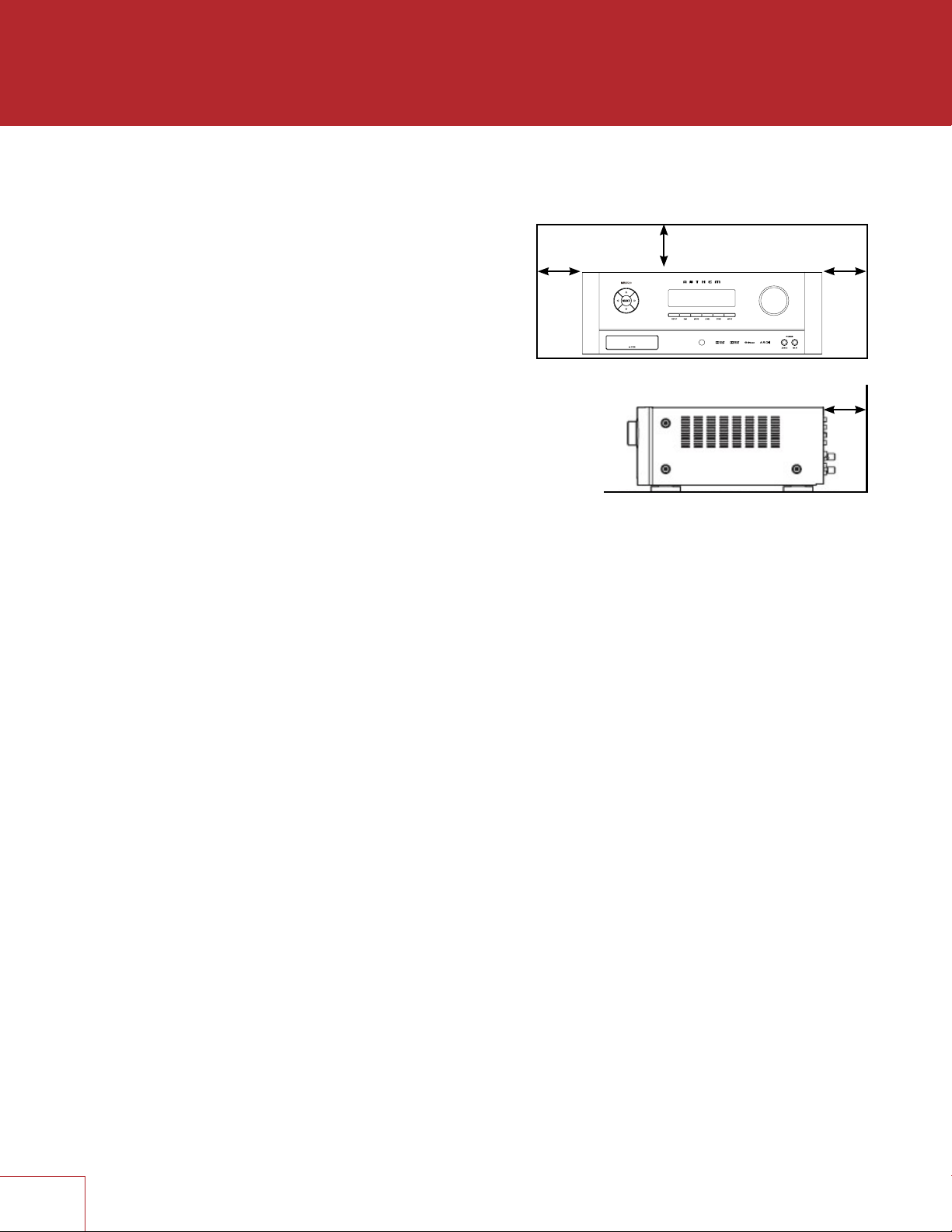
DO NOT LOCATE IN THE FOLLOWING PLACES:
To ensure long-lasting use, do not locate the unit:
• Exposed to direct sunlight.
• Near sources of heat such as heaters.
Left 0.2 m (8 in)
or more
• Highly humid or poorly ventilated.
• Dusty.
• Subjected to mechanical vibrations.
• On wobbly, inclined, or otherwise unstable surfaces.
• Near windows where there is a chance of exposure
to rain, etc.
• On top of an amplifier or other component which
dissipates a great deal of heat.
To ensure proper heat radiation, ensure clearance from
walls and other equipment according to diagram.
IMPORTANT INFORMATION FOR UK CUSTOMERS: DO NOT cut off the mains
plug from this equipment. If the plug fitted is not suitable for the power points
in your home or the cable is too short to reach a power point, then obtain an
appropriate safety approved extension lead or consult your dealer. If, nonetheless,
the mains plug is cut off, REMOVE THE FUSE and dispose of the PLUG
immediately, to avoid possible shock hazard by inadvertent connection to the
mains supply. If this product is not provided with a mains plug, or one has to be
fitted, then follow the instructions given below:
IMPORTANT: DO NOT make any connection to the larger terminal which is
marked with the letter “E” or by the safety earth symbol or colored GREEN
or GREEN AND YELLOW.
The wires in the mains lead on this product are colored in accordance with the
following code:
BLUE – NEUTRAL
BROWN – LIVE
As these colors may not correspond with the colored markings identifying the
terminals in your plug, proceed as follows:
The BLUE wire must be connected to the terminal marked with the letter
“N” or colored BLACK.
The BROWN wire must be connected to the terminal marked with the letter
“L” or colored RED.
When replacing the fuse, only a correctly rated and approved type should
be used, and be sure to re-fit the fuse cover. If in doubt consult a competent
electrician.
Above 0.2 m
(8 in) or more
Behind 0.2 m (8 in) or more
Right 0.2 m
(8 in) or more
IV
Page 6
NOTES ON ENVIRONMENTAL PROTECTION
At the end of its useful life, this product must not be disposed of with regular household
waste but must be returned to a collection point for the recycling of electrical and
electronic equipment. The symbol on the product, user’s manual and packaging,
point this out. The materials can be reused in accordance with their markings. Through
re-use, recycling of raw materials or other forms of recycling of old products, you are
making an important contribution to the protection of our environment. Your local
administrative office can advise you of the responsible waste disposal point.
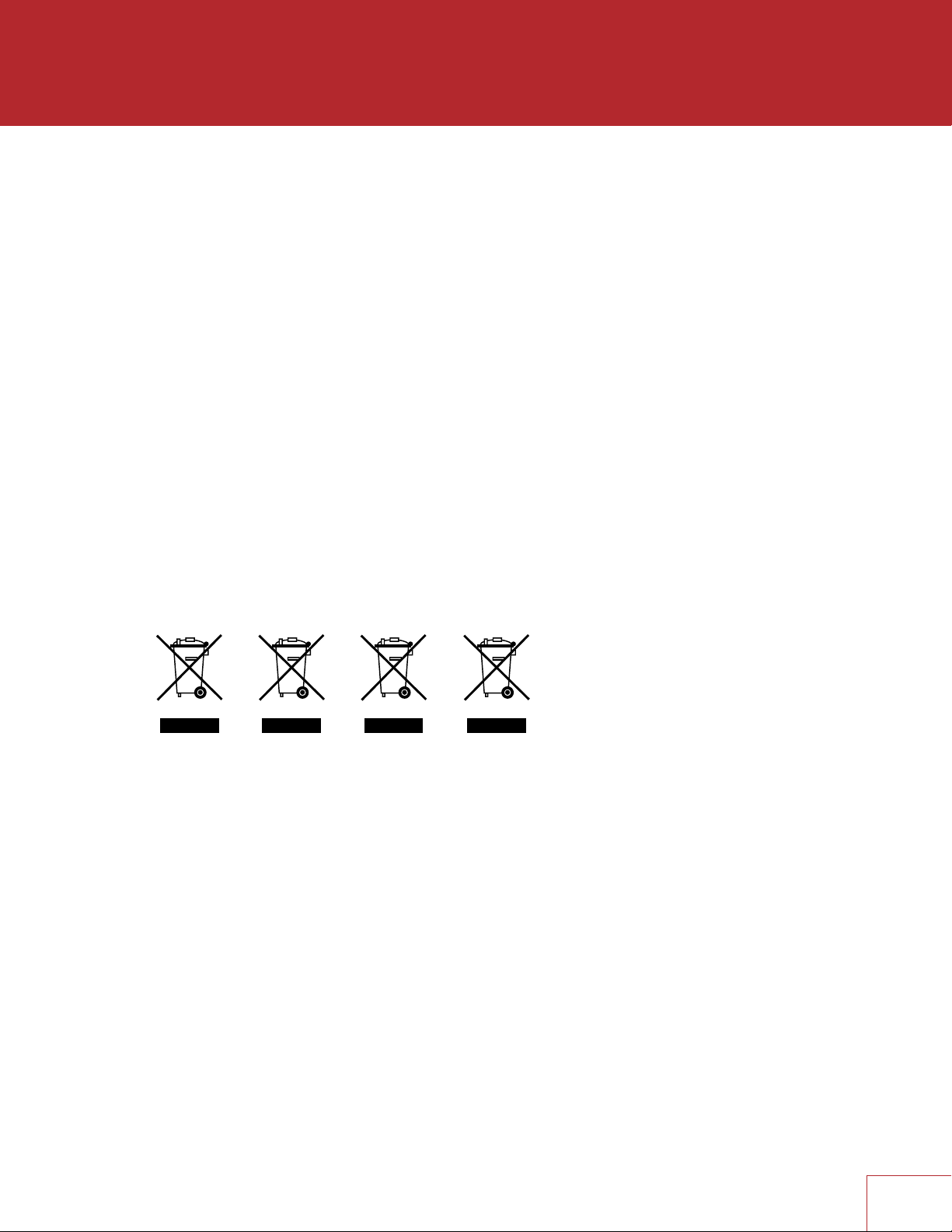
INFORMATION ABOUT COLLECTION AND DISPOSAL OF WASTE BATTERIES
(DIRECTIVE 2006/66/EC OF THE EUROPEAN PARLIAMENT AND THE COUNCIL OF
EUROPEAN UNION) (for European customers only)
Batteries bearing any of these symbols indicate that they should be treated as “separate
collection” and not as municipal waste. It is encouraged that necessary measures are
implemented to maximize the separate collection of waste batteries and to minimize
the disposal of batteries as mixed municipal waste. End-users are exhorted not to
dispose waste batteries as unsorted municipal waste. In order to achieve a high level
of recycling waste batteries, discard waste batteries separately and properly through
an accessible collection point in your vicinity. For more information about collection and
recycling of waste batteries, please contact your local municipality, your waste disposal
service or the point of sale where you purchased the items.
By ensuring compliance and conformance to proper disposal of waste batteries,
potential hazardous effects on human health is prevented and the negative impact of
batteries and waste batteries on the environment is minimized, thus contributing to the
protection, preservation and quality improvement of the environment.
CdHgPb
Anthem and any related party assume no liability for the user’s failure to comply with any
requirements.
Anthem, AnthemLogic, ARC, Sonic Frontiers, and Paradigm are trademarks or
registered trademarks of Paradigm Electronics Inc. © Paradigm Electronics Inc. All rights
reserved. The information contained herein may not be reproduced in whole or in part
without our express written permission. We reserve the right to change specifications
or features without notice as design improvements are incorporated.
Manufactured under license from Dolby Laboratories. Dolby, Dolby Atmos, Pro Logic,
and the double-D symbol are trademarks of Dolby Laboratories.
For DTS patents, see http://patents.dts.com. Manufactured under license from DTS
Licensing Limited. DTS, Play-Fi, the Symbol, DTS in combination with the Symbol,
Play-Fi in combination with the Symbol, DTS:X, and the DTS logo are registered
trademarks or trademarks of DTS, Inc. in the United States and/or other countries.
© DTS, Inc. All Rights Reserved
HDMI, the HDMI logo and High-Definition Multimedia Interface are trademarks or
registered trademarks of HDMI Licensing LLC.
All other trademarks are the property of their respective owners.
V
Page 7

LICENSE INFORMATION FOR THE SOFTWARE USED IN THE UNIT
This product contains one or more free or open source software programs originating
from third parties. This free and open source software is subject to the terms of the GNU
General Public License, GNU Library/Lesser General Public License, or other different and/
or additional copyright licenses, notices, and disclaimers. To understand your rights under
these licenses, please refer to the specific terms of the licenses, notices, and disclaimers,
which are provided in the links below.
To receive a copy of the source code for the open source software programs included in this
product, please make your request to our customer service center.
Paradigm Electronics will distribute such source code to you on a disc for a charge covering
the cost of performing such distribution, such as the cost of media, shipping and handling.
All of the above referenced licenses, notices, and disclaimers are reproduced and available
with such source code. However, note that we make no guarantees concerning the source
code. Please also understand that we do not offer support for the contents of the source
code. This offer is valid for a period of three (3) years following the date of distribution of this
product by Paradigm Electronics.
This section describes software license used for this unit. To maintain the correct content,
the original (English) is used.
The Spotify software is subject to third party licenses found here:
www.spotify.com/connect/third-party-licenses
GPL (GNU-General Public License)
Linux Kernel 2.6.29 https://kernel.org/
libao http://www.xiph.org/ao/
bridge-utils http://www.linuxfoundation.org/collaborate/workgroups/networking/bridge
busybox http://www.busybox.net/
Ebtables http://ebtables.netfilter.org/
Wget http://www.gnu.org/software/wget/
LGPL (GNU LESSER GENERAL PUBLIC LICENSE) LICENSE
LIVE555 http://www.live555.com/
mpg123 http://mpg123.de/
ffmpeg http://www.ffmpeg.org/
avahi http://www.avahi.org/
BSD LICENSE
Libupnp http://pupnp.sourceforge.net/
Opus codec http://www.opus-codec.org/
MIT/X DERIVATE LICENSE
CURL http://curl.haxx.se/
ACADEMIC FREE LICENSE (AFL)
dbus http://www.freedesktop.org/wiki/
OPENSSL LICENSE
OpenSSL https://www.openssl.org/
MIT LICENSE
LibXML2 http://www.xmlsoft.org/
OTHERS: https://github.com/abrasive/shairport/blob/master/LICENSES
Abrasive https://github.com/abrasive/shairport
VI
Page 8

TABLE OF CONTENTS
INTRODUCTION
1 1.1 Before Making Connections
1 1.2 In-Use Notices
2 1.3 Front Panel
3 1.4 MRX 720 Rear Panel
4 1.5 MRX 1120 Rear Panel
5 1.6 AVM 60 Rear Panel
6 1.7 Remote Control
7 1.8 Speaker Positioning
CONNECTIONS
10 2.1 Video Input and Output
11 2.2 Audio Connections
14 2.3 Antenna
14 2.4 Local Area Network
14 2.5 12 Volt Trigger
14 2.6 Infra Red
14 2.7 Power
SETUP
17 3.1 Speaker Setup
19 3.2 Bass Managment
20 3.3 Listener Position
21 3.4 Level Calibration
23 3.5 Input Setup
26 3.6 Preferences / Line Output
28 3.7 Network / Remote Control
31 3.8 General Configuration
33 3.9 Save / Load Settings
34 3.10 System Information
ANTHEM ROOM CORRECTION
36 4.1 Before Starting
36 4.2 ARC Software Installation
37 4.3 Microphone Stand Assembly
37 4.4 Microphone Positioning
37 4.5 Measurement
39 4.6 Manual Mode and Targets
40 4.7 Advanced Subwoofer Targets
41 4.8 Printing A Report
OPERATION
42 5.1 Power On / Off and Volume
42 5.2 Zone 2 Operation
43 5.3 Input Selection
43 5.4 Tuner
44 5.5 DTS Play-Fi
44 5.6 Level Trim
45 5.7 Bass / Treble / Balance
45 5.8 Lip-Sync
45 5.9 Listening Modes
46 5.10 Dolby Volume and Dynamic Range Control
46 5.11 Display Brightness
46 5.12 Info Display
47 Limited Warranty
Page 9

INTRODUCTION
1.1 BEFORE MAKING CONNECTIONS
Check that you have received all items listed below and report discrepancies to your
dealer as soon as possible. In case the unit needs to be transported in the future, keep
the packing materials. Retain the invoice that you received from your authorized Anthem
dealer at time of purchase – without it, service will not be provided under warranty.
• AVM Processor or MRX Receiver
• Remote control
• FM antenna
• Wireless network antennas (2)
• 2 AAA batteries
• IEC power cord (US / UK / EU / CN types are supplied by factory, other types are
normally provided by the local distributor)
Additional items in Anthem Room Correction kit (ARC):
• USB Microphone
• Microphone clip
• Telescopic stand with boom
• USB cable
• CAT5 cable
1.2 IN-USE NOTICES
• Disconnect the power cord before connecting or disconnecting any components.
• If the AVM/MRX was transported or stored in the cold, let it reach room temperature
before use.
• Due to continuing advances, operational characteristics may change. If this manual
contains discrepancies please check www.anthemAV.com for the latest manual or
software.
1
Page 10
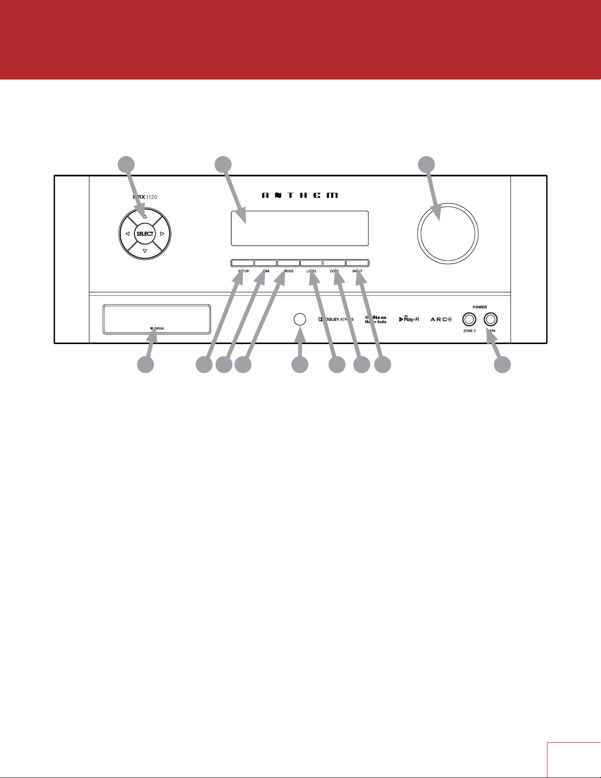
1.3 FRONT PANEL
(MRX 1120 model shown.)
1 2
12
1 – Navigation buttons
2 – Display
3 – Volume, level functions, and character selection
4 – Power / standby
5 – Input selection
6 – Zone 2 selection
7 – Level selection
8 – Remote control sensor location
9 – Mode selection
10 – Display brightness
11 – Setup menu selection
12 – (Behind Cover) Headphone jack, HDMI/MHL jack, USB jack for software updates
11 5
910
3
4678
2
Page 11

1.4 MRX 720 REAR PANEL
MRX 720US
2015.10.26
US model shown. EU model is similar.
PRINTING : WHITE
FILM NO.:150909-3
2
1
18
3 4
5 6 7
2
1 – FM antenna connection
2 – Wireless antenna connectors
3 – HDMI inputs - HDMI7 supports MHL
4 – HDMI outputs - HDMI1 supports Audio Return Channel
5 – Local area network connection for IP control and Anthem Room Correction
6 – USB jack for factory service
7 – Wireless setup button
8 – AC input
9 – RS-232 interface (bidirectional) for serial control
10 – IR input and trigger output
11 – Coaxial digital audio inputs
12 – Optical digital audio inputs and output
13 – Speaker connections
14 – Zone 2 audio output
15 – Line audio output
16 – Analog audio inputs
17 – Main pre-out connections
18 – Chassis ground screw
1617
1415
13
12
11
10
9
8
3
Page 12

1.5 MRX 1120 REAR PANEL
MRX 1120US
2015.10.26
US model shown. EU model is similar.
PRINTING : WHITE
FILM NO.:150907-3
2
1
18
3 4
5 6 7
2
1 – FM antenna connection
2 – Wireless antenna connectors
3 – HDMI inputs - HDMI7 supports MHL
4 – HDMI outputs - HDMI1 supports Audio Return Channel
5 – Local area network connection for IP control and Anthem Room Correction
6 – USB jack for factory service
7 – Wireless setup button
8 – AC input
9 – RS-232 interface (bidirectional) for serial control
10 – IR input and trigger output
11 – Coaxial digital audio inputs
12 – Optical digital audio inputs and output
13 – Speaker connections
14 – Zone 2 audio output
15 – Line audio output
16 – Analog audio inputs
17 – Main pre-out connections
18 – Chassis ground screw
1617
1415
13
12
11
10
9
8
4
Page 13

1.6 AVM 60 REAR PANEL
AVM 60US
2015.10.26
US model shown. EU model is similar.
PRINTING : WHITE
FILM NO.:150913-3
2
1
18
3 4
5 6 7
2
1 – FM antenna connection
2 – Wireless antenna connectors
3 – HDMI inputs - HDMI7 supports MHL
4 – HDMI outputs - HDMI1 supports Audio Return Channel
5 – Local area network connection for IP control and Anthem Room Correction
6 – USB jack for factory service
7 – Wireless setup button
8 – AC input
9 – RS-232 interface (bidirectional) for serial control
10 – IR input and trigger output
11 – Coaxial digital audio inputs
12 – Optical digital audio inputs and output
13 – Balanced outputs
14 – Zone 2 audio output
15 – Line audio output
16 – Analog audio inputs
17 – Main pre-out connections
18 – Chassis ground screw
1617
1415
13
12
11
10
9
8
5
Page 14

1.7 REMOTE CONTROL
1 – Main zone power on and standby
2 – Bass, Treble, Balance, Channel Level,
Front panel dimmer
3 – Numeric keypad for tuner presets
4 – Input list
5 – Tuner preset
6 – Setup menu
7 – Info and status
8 – Navigation controls
9 – Clear for deleting input configurations
and tuner presets, and clearing new entry
10 – Dolby Volume and Dolby Digital Dynamics
11 – Listening mode
12 – Volume
13 – Last menu entry and Home Button for MHL Sources
14 – Mute
15 – Next/previous tuner preset, setup menu
page up/down
16 – Lip-sync
17 – Backlight
18 – Zone 2 controls
The left/right buttons also select previous/next input.
The up/down buttons also control tuner station.
10
11
1
2
BASS
3
4
TREB
1
4
BALDIM
LEVEL
2
5
3
6
5
7
8
0
6
SETUP
7
SELECT
9
INPUTPRESET
i
8
CLEAR
VOL
DYN
LIP-SYNC
9
MODE
LAST
13
PG/PR
14
12
VOL
VOL
ZONE 2
RC-MRX 2
INPUT
15
16
PR
PR
17
18
6
Page 15
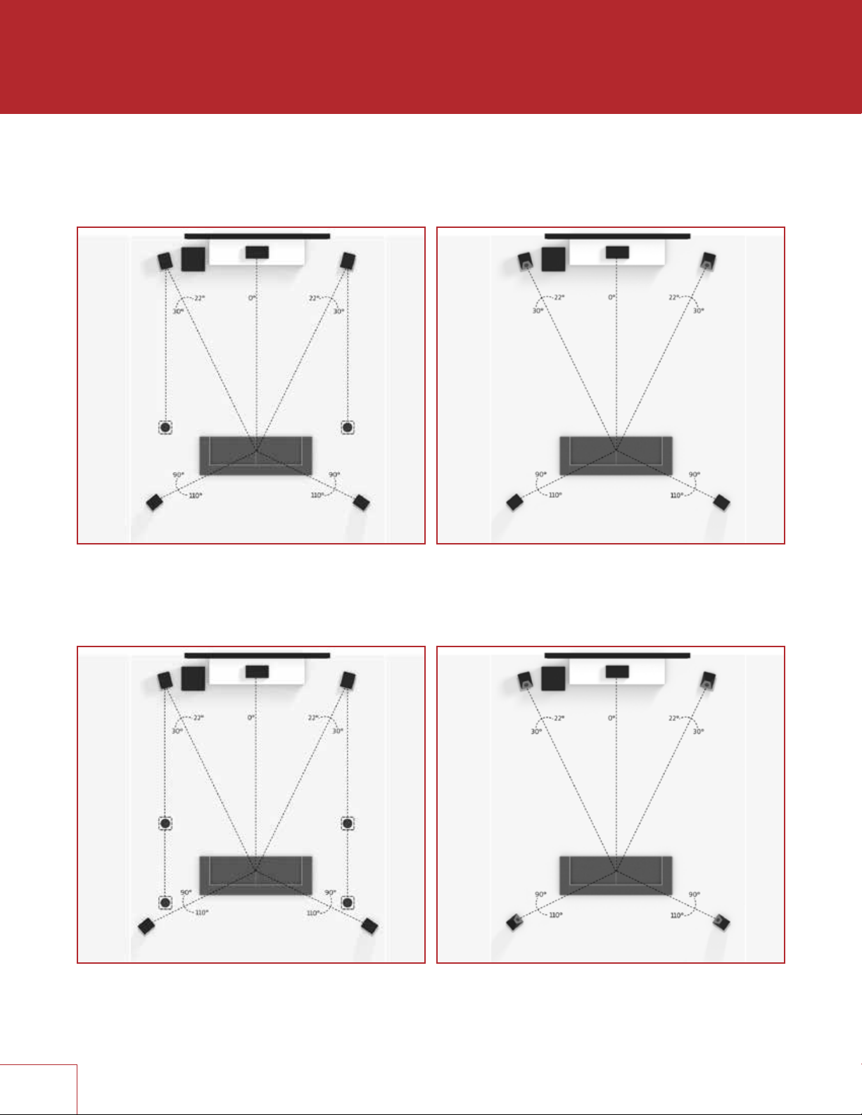
1.8 SPEAKER POSITIONING
These illustrations show possible speaker placements.
5.1.2 Configuration
with one pair in-ceiling height speakers
5.1.2 Configuration
with Dolby enabled front speakers
5.1.4 Configuration
with two pair in-ceiling height speakers
7
5.1.4 Configuration
with Dolby enabled front and rear speakers
Page 16
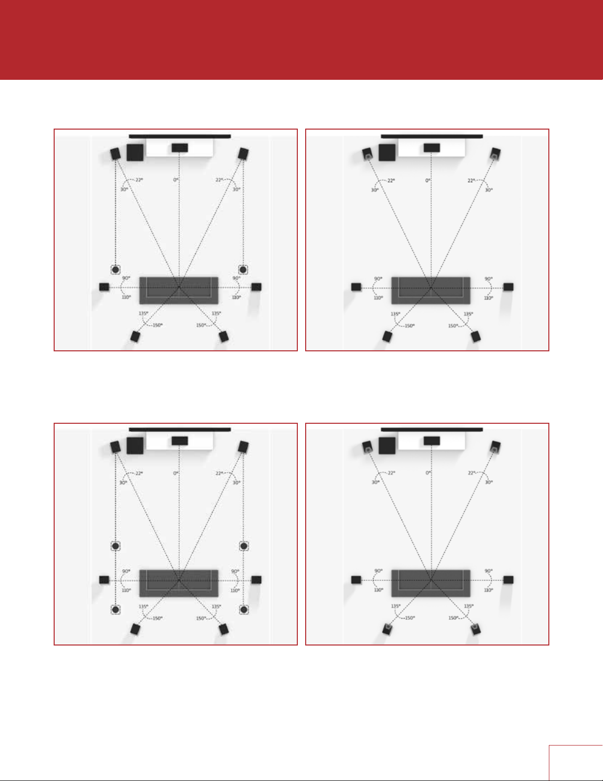
7.1.2 Configuration
with one pair in-ceiling height speakers
7.1.2 Configuration
with Dolby enabled front speakers
7.1.4 Configuration
with two pair in-ceiling height speakers
7.1.4 Configuration
with Dolby enabled front and rear speakers
8
Page 17
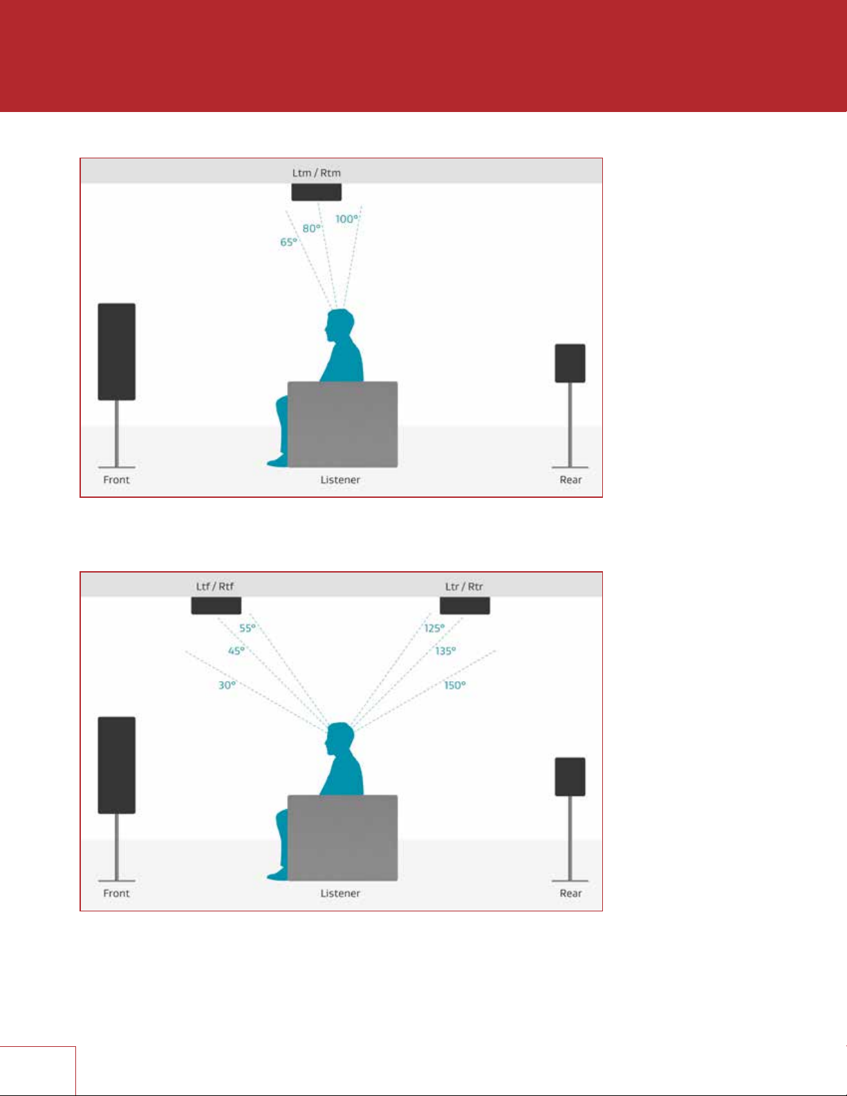
One pair in-ceiling height speakers (side view)
Two pair in-ceiling height speakers (side view)
9
Page 18

CONNECTIONS
This section describes connections between system components. Configuration of
input and output will be discussed later, in section 3.
2.1 VIDEO INPUT AND OUTPUT
With HDMI connection, video and audio are carried together. Connect HDMI output
from MRX to a display with HDMI input – one with the appropriate version of Highbandwidth Digital Content Protection (HDCP) is required to display copy-protected
material.
HDMI input 7 is also an MHL input (Mobile High-definition Link). Use this input if the
source component also supports MHL, for example smaller media players that receive
power through this interface.
Insert HDMI cables gently because the connector is more delicate than traditional ones.
Damaged cables can damage jacks, and replacement jacks are not covered by warranty
therefore replacing HDMI cables is recommended if there is any chance that the existing
ones have been used improperly.
Use only certified High Speed cables and connecting devices. Cables and connecting
devices that worked in an older setup do not necessarily work with newer video formats
such as Deep Color, UHD, or high frame rates. If you are using adapters or port savers,
start troubleshooting by eliminating them since they can affect bandwidth.
10
Page 19
2.2 AUDIO CONNECTIONS
AUDIO INPUTS AND OUTPUTS
Digital audio sources can be connected using an HDMI, coaxial or optical cable. These
connections carry linear PCM, Dolby Digital, and DTS audio formats. HDMI connection is
generally preferred to ensure that lossless audio is used where sources provide it although
optical/coax can also be used for sources outputting 2-channel PCM, Dolby Digital 5.1, and
DTS 5.1 without affecting audio quality.
Audio on the HDMI outputs is 2-channel PCM as this is meant for the TV’s use.
HDMI AUDIO RETURN CHANNEL
If the TV provides audio through HDMI ARC, for example when it accesses streaming media
sources, it can send the audio to the MRX through HDMI output 1, eliminating the need for
a separate audio connection. CEC control, described in a later section, must be enabled for
Audio Return Channel to function.
If the display reads “Dial Norm Offset -4.0 dB” at the start of a movie, it is indicating that the
encoded level is higher than standard by 4.0 dB – the playback level of all channels is then
automatically reduced by 4 dB.
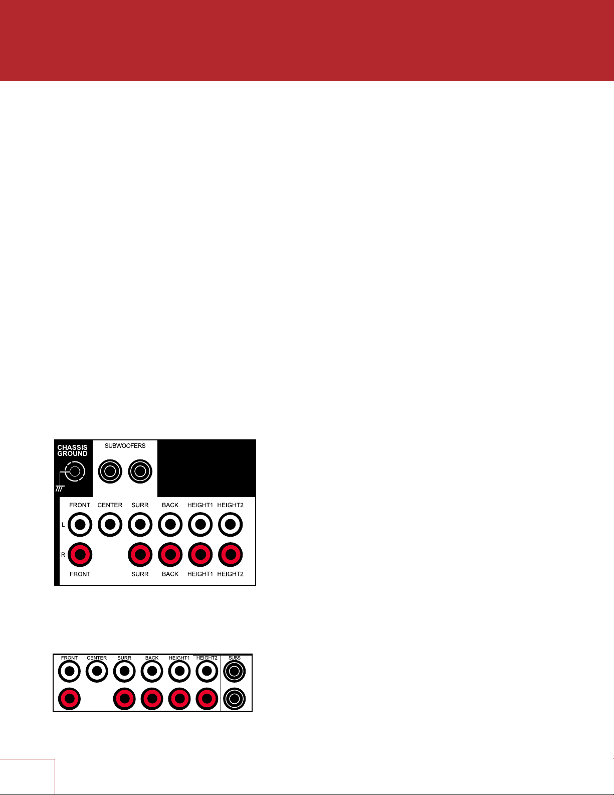
PREAMP OUTPUTS
The pre-outs are variable according to the volume control and can be used with external
amplification.
MRX 720 / 1120
AVM 60
The RCA and XLR outputs have a signal at the same
time. XLR connection is suitable for longer cables.
11
Page 20

LINE OUTPUT AND ZONE 2 OUTPUT
Line output is a 2-channel version of the selected input with fixed output level. This can be
used with a headphone amp which has its own volume control.
Zone 2 has its own volume control and can be used two ways:
- For independent source selection, connect the source using analog input, or optical/
coaxial input as long as the source is 2-channel PCM. This connection can be used in
conjunction with HDMI connection for the main zone.
- For similar operation as Line Output but with volume control, set Follow Main to Always
in the setup menu (setup is explained later).
OPTICAL AND COAXIAL DIGITAL AUDIO
If HDMI audio from a Dolby Digital, DTS, or 2-channel PCM source is problematic or takes
too long to switch, use of coax/optical audio connection is recommended (HDMI video can
still be used). Older cable and satellite AVM/MRXs often benefit from this.
The optical output provides a passthrough of coax/optical input.
12
Page 21

SPEAKER CONNECTIONS (MRX ONLY)
Using speaker wire, connect the positive (+) connection on the speaker to the positive
(+) binding post on the appropriate amplifier output, and the negative (–) connection
on the speaker to the negative (–) binding post on the same amplifier channel using
cable that is insulated to handle the maximum output of the amplifier. Carefully remove
insulation using a wire stripper.
Do not connect more than one speaker to each amplifier output. Be sure that power is
turned off when connecting or disconnecting anything, and that the speakers are rated
for use with this AVM/MRX.
MRX 720
MRX 1120
US models allow banana connectors. If using them, first turn the binding post until it is
closed to allow the plug to be fully inserted.
13
Page 22

2.3 ANTENNA
Connect the FM antenna to the FM ANTENNA connector.
Later, when unit is operating move the antenna to find best reception.
2.4 LOCAL AREA NETWORK
A network connection is required for configuring Anthem Room
Correction, using the Play-Fi App, or using IP control. To use a wired
connection, simply connect your router using CAT5 cable.
Wireless connection is explained in the setup section – note that if the AVM/
MRX is mounted in a metal rack, wired network connection is recommended
instead especially if the wireless router is in a different room or if anything else
can impact signal strength. If using wireless connection, add the two network
antennas to the rear panel.
If a firewall is used for security, ensure that the AVM/MRX is permitted to join the network.
2.5 12 VOLT TRIGGER
2.6 INFRA RED
An external IR receiver allows the remote control to be used from another
location in your home – connect the AVM/MRX from an external IR hub to the
IR IN jack. Most standard IR repeater kits can be used but to avoid problems
test compatibility before installing permanently.
2.7 POWER
If another system component has a trigger input it can be activated by
the AVM/MRX. Connect the AVM/MRX’s trigger output using a cable
with 3.5mm mini plugs. The AVM/MRX provides flexible trigger options.
Through the setup menu, you can specify the conditions for enabling
triggers.
Connect the power cord to the AVM/MRX and the
power source.
14
Page 23

EXAMPLE 1
AVM 60US
2015.10.26
PRINTING : WHITE
FILM NO.:150913-3
HDMI OUT
1
2
34
LAN
HDMI IN
HDMI IN
WAN
LAN
2
1
34
15
HDMI OUT
Page 24

SETUP
For optimum performance and enjoyment, your AVM/MRX should be properly set up.
This may appear like a lot of work but most settings do not need to be changed from
defaults. The important ones relate to your display and input connections, and distance
from listening area to each speaker. Anthem Room Correction will set crossovers and
channel levels. The rest is preference and the listening mode presets, for example,
should be set after you have played various sources and determined which surround
modes you like most.
RemoteFront Panel
INPUT
SETUP
SELECT
CLEAR
LAST
PG/PR
HOW TO NAVIGATE IN THE SETUP MENU
• Press Setup to enter or exit
• Use the up/down/left/right buttons to move through menus and selections
• Press PG/PR up/down to skip page
• Press Select to make a selection or to start/finish editing the item
• Pressing Last while editing returns the item to its previous setting
• Press Clear to set the item to its default value
The menu below appears on your display once pressing Setup. On-screen, up to nine
menu items are displayed at once although for clarity this manual shows all items in
each menu together.
Main Menu
Speaker Setup
Bass Management
Listener Position
Level Calibration
Input Setup
Preferences / Line Output
Network / Remote Control
General Configuration
Save / Load Settings
System Information
16
Page 25

3.1 SPEAKER SETUP
If your source components also have bass management and time alignment, be sure to
disable them by setting all channels “large” and to the same distance from listener since
the AVM/MRX will be performing these tasks. Audio quality will be degraded if these
processes are performed twice.
Speaker Setup
Speaker Placement Guide
Back Amp Main Back
Height 2 Amp Height 2
Height 1 Front In-Ceiling
Height 2 Back In-Ceiling
Config 1 Speaker Profile
Config 2 Speaker Profile
Config 3 Speaker Profile
Config 4 Speaker Profile
SPEAKER PLACEMENT GUIDE
This shows various speakers in a room to help you with settings in other menus pertaining to
speaker type and position.
BACK AMP (MRX Only) and HEIGHT 2 AMP (MRX 1120 Only)
By default, MRX 1120 has amplification for 7.1.4 main speakers, and the MRX 720 for
7.1 main speakers. Amplification for the back and height channels can be reassigned for
use with the following configurations:
MRX 1120:
5.1.4 main speakers and two Zone 2 speakers
7.1.2 main speakers and two Zone 2 speakers
MRX 720:
5.1.2 main speakers
5.1 main speakers and two Zone 2 speakers
HEIGHT SPEAKER TYPE AND POSITION
Two or four speakers may be installed in the ceiling or on the wall near the ceiling. In addition
a special type of height speaker, referred to as Dolby-enabled, may be placed on top of
existing speakers. It works by bouncing height information off the ceiling.
Using the room layout diagrams as a guide, select from the following possibilities to match
your height speakers:
Front In-Ceiling
Front Dolby
Front On-Wall
Middle In-Ceiling
Middle Dolby
Back In-Ceiling
Back Dolby
Back On-Wall
1717
Page 26

FOUR CONFIGURATIONS
One speaker configuration is normally suitable but alternate sets of bass management,
listening position, level calibration, and ARC equalization values can be entered and stored.
This can be useful if your installation varies according to sound-altering characteristics such
as screen up vs down, door open vs closed, or with subwoofer vs without.
Speaker Setup
Profile Name Config 1
Subwoofer On
Center On
Surround On
Back On
Front In-Ceiling On
Back In-Ceiling On
PROFILE NAME
Using the navigation keys and volume knob each profile can be renamed, up to 8 characters
long. When finished, press Select but note that the profile name is best set in Anthem Room
Correction (Targets panel) because during file upload the name in the menu is overwritten by
the one in ARC.
SUBWOOFER / CENTER / SURROUND etc.
If using Anthem Room Correction, these items will be set during measurement. Set to “On”
if you are using these speakers, “Off” if you are not. This is an important step so no sounds
go missing because by setting unavailable channels to “Off”, the sound that would have
come from those speakers is rerouted to available speakers.
The subwoofer plays two things, LFE (Low Frequency Effects) channel in multichannel
soundtracks and bass from remaining channels using the crossover. Some people prefer
to play music through a system that does not use a subwoofer though it should be
noted that the reason often cited is that the subwoofer does not blend well with the main
speakers. In contrast, Anthem Room Correction excels in integrating the subwoofer with
the main speakers, so in this case using a subwoofer is recommended for all sources. The
subwoofer normally plays bass that is louder, deeper, and less distorted than that of a fullrange speaker, and it uses its own amplifier.
18
Page 27

3.2 BASS MANAGEMENT
In this menu, information about your speakers is used so that bass does not
become distorted. If using Anthem Room Correction, these items will be set during
measurement, so you may skip this menu.
If your subwoofer has a crossover, it should be bypassed – set its frequency control to
the highest frequency.
The bass manager is a crossover that divides audio in two frequency bands suitable
for subwoofer/satellite speaker systems. The result is a lower bass level for satellite
speakers, and no midrange/treble going to the subwoofer.
Highlighting Bass Management then pressing Select displays this menu:
Bass Management
Config 1 Speaker Profile
Config 2 Speaker Profile
Config 3 Speaker Profile
Config 4 Speaker Profile
Four configurations may be set up. Each contains the following:
Bass Management
Subwoofer LPF for LFE 120 Hz
Front Crossover 80 Hz
Center Crossover 80 Hz
Surround Crossover 80 Hz
Back Crossover 80 Hz
Front In-Ceiling Crossover 80 Hz
Back In-Ceiling Crossover 80 Hz
CROSSOVER FREQUENCY
The range is 40 to 250 Hz in 10 Hz steps except for 200, 225 and 250 Hz, or Off which
bypasses the crossover. Note that a crossover does not cut frequencies off like a cliff,
but rolls them off according to a slope. If set to 80 Hz, for example, frequencies lower
than 80 Hz are still played. Setting the crossover to the lowest number on your speaker’s
specification page is unlikely to provide the best result.
19
Page 28

3.3 LISTENER POSITION
Through these settings, sound coming from all speakers is coordinated to reach the
listening area at the same time. This way, proper imaging is achieved. The channel
with the greatest distance setting will have no delay while channels with shorter distance
settings will be delayed accordingly.
Distances may be set before or after running ARC (ARC does not set distances).
Listener Position
Units feet
Config 1
Config 2
Config 3
Config 4
For measurement units, select feet or metres.
These settings are displayed for each configuration:
Listener Position
Subwoofer 12 Feet
Front Left 12 Feet
Center 12 Feet
Front Right 12 Feet
Surround Right 12 Feet
Back Right 12 Feet
Back Left 12 Feet
Surround Left 12 Feet
Front In-Ceiling Left 12 Feet
Front In-Ceiling Right 12 Feet
Back In-Ceiling Left 12 Feet
Back In-Ceiling Right 12 Feet
Enter the distance between your primary listening area and each speaker. Range is
0-30 ft in 1 ft increments or 0-9 m in 0.3 m increments.
20
Page 29

3.4 LEVEL CALIBRATION
Level Calibration uses internally generated test noises to match speaker output levels
at the listening position. These noises are also a way of checking system connections
between receiver, amplifier, and speaker. Audio calibrations from home theater setup
discs are not recommended – some use incorrect methods.
If using Anthem Room Correction, these items will be set during measurement.
A sound pressure level (SPL) meter with C-weighting is recommended if not using ARC,
especially to set the subwoofer level. Measure the sound pressure from the listening
position while pointing the meter up. Hold it away from your body to prevent reflections.
Level Calibration
Config 1
Config 2
Config 3
Config 4
These settings are displayed for each configuration:
Level Calibration
Test Noise Off
Dolby Offset / Calibration Level 0 dB
Subwoofer 0 dB
Front Left 0 dB
Center 0 dB
Front Right 0 dB
Surround Right 0 dB
Back Right 0 dB
Back Left 0 dB
Surround Left 0 dB
Front In-Ceiling Left 0 dB
Front In-Ceiling Right 0 dB
Back In-Ceiling Left 0 dB
Back In-Ceiling Right 0 dB
TEST NOISE
To play the test noise, select “On”. Use the up/down buttons to move the noise to the other
speakers.
DOLBY OFFSET / CALIBRATION LEVEL
This is the master volume for this menu’s test noises. Changing it changes the output of all
channels. The noise comes out of the left front channel.
21
Page 30

CHANNEL LEVEL
If you’re calibrating by ear, use the remote control and sit in the listening area. Adjust each
channel’s loudness until all levels sound the same. If using an SPL meter, adjust level so it
reads 75 dB for each channel. If Noise Level is set while Front-L is at 0 dB, no adjustment
of Front-L is needed since the output is the same. If using a powered subwoofer, make a
rough adjustment with its input level control before setting sub level in this menu or using
ARC. Speakers set to “Off: in the Bass Management menu are skipped.
Note that if ARC sets levels and is then turned off, the subwoofer level should be reduced
by the same amount as room gain or the subwoofer level will be elevated when ARC is off.
MULTIPLE SUBWOOFERS
If using multiple subwoofers they should be balanced to one another before
calibrating the rest of your system. If using ARC, simply use the Quick Measure
function to help find flat response as a preliminary step before running full
measurement. If setting up the traditional way, play the subwoofer test noise with
only one subwoofer connected at a time. Set its input level dial so the SPL meter
reads 71 dB from the listening area if using two subs, or 67 dB if using four subs.
Repeat this for the remaining subs. When all are connected the result should be
around 75 dB – make final adjustment in the level calibration menu.
22
Page 31

3.5 INPUT SETUP
Inputs and listening mode presets are configured in this section. From the factory, 5
inputs are set but you may change this to anything from 1 to 30 configurations.
Input Setup
HDMI 1
HDMI 2
HDMI 3
FM
Play-Fi
Add Input
Zone 2 Input Follows Main No
To add an input at the end of the list, highlight Add Input and press Select.
To insert an input, highlight one on the list and press Input. The new input will be
inserted after the highlighted one.
To delete an input, highlight it and press Clear on the remote control.
ZONE 2 INPUT FOLLOWS MAIN
When changed to Yes, any input can go to Zone 2 without separate cabling from the
source, but the Zone 2 will always play whichever input is selected in the main zone.
Multichannel sources get downmixed to 2-channel so all sounds can go to Zone 2.
These settings are displayed for each configuration:
HDMI 1 Input Setup
Input Name HDMI 1
Video Input HDMI 1
Audio Input HDMI
Zone 2 Input Analog 1
Process Analog Audio Input N/A
Speaker Profile Config 1
Anthem Room Correction N/A
Dolby Volume Off
Dolby Volume Leveler N/A
Mode Preset for Stereo Sources Last Used
Mode Preset for Multi-Ch Sources Last Used
DTS Neural:X Mode Non-Direct
Lip Sync 0 ms
23
Page 32

INPUT NAME
Using the navigation keys and volume knob each input can be renamed, up to 8 characters
long. When finished, press Select.
Example – Rename “HDMI 1” to “Blu-ray”:
• Highlight “Input Name” and press Select. The first character will be highlighted in red.
• Use the up/down buttons or volume knob to change “H” to “B”.
• Use the left/right buttons to move to each remaining character and complete the
renaming.
• Press Select to return to the menu
VIDEO INPUT
Select the connection to be used – HDMI1-7 or Front HDMI.
AUDIO INPUT
Select the connection to be used – HDMI, HDMI Audio Return, Digital Coaxial 1-2,
Optical 1-3, Analog 1-5, FM, Play-Fi, None
ZONE 2 INPUT
Select the connection to be used – Coaxial 1-2, Optical 1-3, Analog 1-5, FM Radio,
Play-Fi, None.
Note that with coaxial and optical input, the source must be 2-channel PCM.
PROCESS ANALOG AUDIO INPUT
If changed to No, digital conversion and signal processing are bypassed. Only level
adjustments will be available.
SPEAKER PROFILE
Select the profile to use with this input.
ANTHEM ROOM CORRECTION
The ARC measurement process, described later, will turn this on. To disable room
equalization afterward, change this to “Off”. If measurement info isn’t loaded, “N/A”
is displayed.
DOLBY VOLUME (MAIN ONLY)
Select On or Off. Dolby Volume makes content with large differences in volume easier to
listen to by analyzing it and intelligently adjusting two things – level and frequency response.
It does this continually without causing pumping and breathing artifacts that are common
with traditional dynamic range compressors. In doing so, the volume setting is taken into
account as is our hearing’s declining sensitivity to the lowest and highest frequencies relative
to the midrange as their levels drop. The result is that the perceived frequency response
remains constant while making quieter parts of the content more listenable.
DOLBY VOLUME LEVELER
This applies when Dolby Volume is turned on. The leveling amount can be set from 1 to
9, or Off. Play various sources to find your preferred setting. When Leveler is “Off” the
frequency response adjustment still applies.
24
Page 33

LISTENING MODE PRESETS
A listening mode is processing that enhances source material by increasing the number of
output channels. Each mode performs this its own way, providing its own type of sound.
To find your preference, spend some time listening to various modes using various sources.
To disable presets and make selections entirely on the fly, select “Last Used”. To disable
listening modes altogether, select “None”.
AnthemLogic-Cinema provides the missing link that lets you experience full impact
home theater sound from any 2-channel source. A large, enveloping and dynamic listening
experience is created making 2-channel movies sound more like what is experienced in a
state-of-the art movie theater. Through extensive listening tests a very effective design was
developed, avoiding the use of echo effects which could negatively affect the purity of the
sound.
AnthemLogic-Music enhances the stereo listening experience without detracting from
the stereo soundstage. This is also a minimalist design that uses no echo or reverberation
effects. To ensure that the purity of the stereo music soundstage is in no compromised
when you’re sitting in the “sweet spot” and listening to your favorite stereo recordings, the
center channel is not used.
Dolby Surround upmixes stereo, 5.1, and 7.1-channel content to take full advantage of all
speakers in a Dolby Atmos system.
Unlike previous wideband upmixing technologies, Dolby Surround can steer frequency
bands individually, producing surround sound with precisely located audio elements and
a spacious ambience. Dolby Surround replaces the Dolby Pro Logic II family of upmixers,
offering greater flexibility and superior audio performance.
A Center Spread control accessible by pressing the Mode button enables spreading the
center image across a wider front soundstage. This is suitable when using a wider than
typical screen.
DTS Neural:X uses all speakers in a DTS:X system for an immersive audio experience,
creating separation by placing sounds at different points in the sound field. This mode does
not apply to DTS:X Master Audio, DTS:X, Dolby Atmos, Dolby TrueHD, and Dolby Digital
Plus sources. When the source is a DTS stream, Direct mode plays the audio channels as
they were recorded, whereas Non-Direct mode adapts the audio to your speaker layout if it
is different from the content creator’s.
All Channels sends the left and right channels to the surround channels with equal loudness
while the center channel and subwoofer receive a combination of both.
LIP-SYNC DELAY
If audio is heard before its corresponding image is seen, you can set up to 300 milliseconds
of audio delay – set using synchronization test disc or trial and error. Movies are not always
the best test because sounds including dialog are usually re-recorded after the filming is
completed, and can be slightly out of sync at various points in the recording. Adjustment
can also be made while viewing material after pressing the Lip-Sync button.
25
Page 34

3.6 PREFERENCES / LINE OUTPUT
Here you can set preferences as listed.
Volumes / REC Output
Front Panel Brightness Medium
Front Panel Wake-up Up 1
On-Screen Info Display On
Mute Level Silent
Main Max Volume 0 dB
Zone 2 Max Volume 0 dB
Main Power On Volume -35 dB
Zone 2 Power On Volume -35 dB
Main Power On Input Last Used
Zone 2 Power On Input Last Used
Headphone Mutes Main Pre-Out Yes
Mute Line Out when selecting None
Mute Digital Out when selecting None
FRONT PANEL BRIGHTNESS
Set preferred default brightness.
FRONT PANEL WAKE-UP
When a button is pressed the display can go to a brighter level for 5 seconds – select
None, Up 1 brightness level, Medium, or High. When “None” is selected and the display
is off, the wake-up behaves as Up 1 to indicate that the unit is running.
ON-SCREEN INFO DISPLAY
When changing volume, input, listening mode, etc, the info that is shown on the front
panel is also shown on-screen for 5 seconds. To disable the on-screen info, turn this
setting Off.
MUTE LEVEL
When Mute is pressed, sound can cut out completely or decrease in volume by the
amount that you set to keep some of it in the background. Select from Silent or -5 to
-30 dB in 5 dB steps.
MAXIMUM VOLUME
These settings allow you to limit the volume setting to avoid damaging equipment
and/or hearing.
POWER-ON VOLUME
The volume will be at these levels when the AVM/MRX is turned on. To power-on at the
last used volume, set the volume preset below -90 to make Last Used appear.
POWER-ON INPUT
The input will be the pre-set one or Last Used when the AVM/MRX is turned on.
26
Page 35

HEADPHONE MUTES PRE-OUTS
If using external amplification, changing this to No allows the speakers continue to
playing while headphones are plugged into the front panel.
MUTE LINE OUT OR DIGITAL OUT
If using a recording device, select the input that the recorder’s output is connected to.
This prevents the recorder’s output from being fed back to its input, which can result in
a loud noise.
27
Page 36

3.7 NETWORK / REMOTE CONTROL
Network / Remote Control
Network Status
Device Name AVM 60
Wireless Setup
IP Configuration
Trigger Configuration
TCP Port 14999
Rear IR On
Front IR On
Tx Status On
NETWORK STATUS
This displays the AVM/MRX’s IP address once connected to the local area network.
DEVICE NAME:
This is the name that the AVM/MRX broadcasts, and can be changed using up to 16
characters.
WIRELESS SETUP
Wireless network connection can be set using various methods.
Wireless Setup
From Play-Fi App
Push-Button Setup
Manual Setup
Reset Wireless Settings
FROM PLAY-FI APP
The DTS Play-Fi app for iOS, Android, and Kindle devices streams music to your system
from local and internet sources. It also connects your AVM/MRX to your wireless network
as follows:
1. Install the app on your mobile phone or tablet.
2. Launch the app. It will look for Play-Fi devices - make sure your AVM/MRX has
been on for at least a minute to allow its wireless functions to be ready.
3. When the app finds your AVM/MRX it will temporarily disconnect your mobile
device from the wireless network while connecting it directly to the unit, and it will
ask you to enter your wireless network password. Once you enter it, the app will
send it the AVM/MRX so it can connect to your network.
4. Once the AVM/MRX is connected the app re-connects your mobile device to your
network and over the next minute searches for more Play-Fi devices. If it says that
not Play-Fi devices are on your network, turn your AVM/MRX off and on again,
wait a minute, and tap Search Again in the app.
5. Rename the AVM/MRX as you would like it to appear in the app, for example
“Main System”.
If the app has trouble finding the AVM/MRX at all, make sure that it has adequate wireless
signal strength by placing it close to the router. As well, make sure your mobile device is
near the AVM/MRX when it is searching for devices. If the AVM/MRX still cannot be found,
reset the wireless settings as described below and/or temporarily connect a CAT5 cable
between the AVM/MRX and the router until Play-Fi setup is completed.
28
Page 37

PUSH-BUTTON SETUP
This method can be used if your router has a WPS (Wi-Fi Protected Setup) button. After
making the menu selection, press the button on your router. Push-button mode can also
be enabled by holding the Wireless button on the rear panel for 5 seconds (tap again to
cancel). The LED next to it will change blink style.
MANUAL SETUP
About a minute after making this selection, a list of wireless networks will appear. Select
the one that you want the AVM/MRX to connect to and enter your wireless password with
the on-screen keyboard.
RESET WIRELESS SETTINGS
Select this to connect the AVM/MRX to a different network or to delete the network
connection info and password. The reset is also possible by holding the rear panel button
for 10 seconds (tap to cancel).
IP CONFIGURATION
Settings in this submenu should only be changed if your network administrator gives the
direction or if using Direct Connect to run ARC.
IP Configuration
Mode Auto (DHCP)
IP 192.168.000.001
Subnet Mask 255.255.255.000
MODE
Static IP settings take effect once this is changed to Manual.
TRIGGER CONFIGURATION
When the AVM/MRX’s trigger output is connected to the trigger input of another
component, such as an amplifier or projector, the AVM/MRX can turn it on or off
according to the trigger’s setup.
Trigger Configuration
Trigger Control Menu
Power Main or Zone 2
HDMI 1 Off
HDMI 2 Off
HDMI 3 Off
FM Off
Play-Fi Off
In the example shown, the trigger activates while Main or Zone 2 power is turned on.
Trigger outputs can also be set to activate according to any combination of inputs
instead of Power.
If triggers are to be controlled through IP or RS-232, change “Menu” to “RS-232/IP”.
29
Page 38

TCP PORT
Change this only if there is a conflict with another application that uses 14999. Available
settings are 1025 to 49150.
REAR AND FRONT IR
This allows you to disable each of the AVM/MRX’s infra-red inputs, which can be useful
when the AVM/MRX is connected to an IR repeater and is receiving too many signals.
Note that the moment that you disable the front IR input, you will not be able to control
the AVM/MRX the traditional way from the remote control – re-enable the IR input using
the front panel buttons. If your remote control appears to not be working and you have
checked the batteries, check this menu next before contacting technical support.
TX STATUS
When enabled, all commands, status changes, and control information are reported
through the Ethernet and RS-232 connections.
30
Page 39

3.8 GENERAL CONFIGURATION
This menu contains power saving, control, and tuner options.
General Configuration
Auto Off 20 minutes
IP Control On
Standby IP Control Off
Standby HDMI Bypass Off
CEC Control Off
CEC Power Off Control Disabled
CEC Power On Control Disabled
FM Tuner Steps 100 kHz
AUTO OFF
When there is no input signal the AVM/MRX will turn off after the selected time: 5, 10, or
20 minutes, 1, 2, or 6 hours, or Never.
IP CONTROL
With this setting you can enable/disable response to networked Internet Protocol
commands.
STANDBY IP CONTROL
tWhen disabled, the AVM/MRX goes into a low-consumption standby mode and does
not sense IP commands while in it. To make it respond to a power-on command or to
keep DTS Play-Fi connected to the network so it can be used immediately after poweron, enable this setting. This can also be used with RS-232 control to avoid sending a
wake-up command.
STANDBY HDMI BYPASS
This option allows use of an HDMI source without turning on the AVM/MRX. Select
HDMI 1-7, Front HDMI, or Last Used. The standby LED on the front panel changes to
red. Your TV may need setup to allow the sound to come from its speakers – check its
manual.
31
Page 40

CEC
When Consumer Electronics Control is enabled it allows controlling one HDMIconnected component using another’s remote control, as long as CEC is also enabled
in the other components. Note that when component brands are mixed this control
system may not be reliable.
CEC Control must also be On for Audio Return Channel, described in an earlier section,
to function.
With CEC, turning on one component in the system can turn on the rest of the system,
same with turning one component off. You may or may not want this which is why
separate options are provided for Power Off and Power On control. When either
is disabled, the corresponding power commands sent by other HDMI-connected
components are ignored. This is also useful if you would like to use Audio Return
Channel but not one-touch power.
TUNER STEPS
Set according to your country’s radio standards – 50, 100, 200 kHz.
After changing CEC settings or
loading factory defaults it may be
necessary to briefly disconnect
and reconnect the HDMI cable
between the AVM/MRX and TV
or source component for the new
settings to be recognized.
32
Page 41

3.9 SAVE / LOAD SETTINGS
Save / Load Settings
Save User Settings
Load User Settings
Reset on-the-fly Settings
Load Factory Defaults
SAVE/LOAD USER SETTINGS
After selecting Save User Settings and confirming, all menu settings will be stored.
If you change settings later and want to recall the saved settings, select Load User
Settings and confirm.
RESET ON-THE-FLY SETTINGS
After selecting and confirming, all non-menu settings such as level and bass/treble will
be reset.
LOAD FACTORY DEFAULTS
After selecting and confirming, all menu settings will be reset.
SYSTEM RESET
This is not a menu setting. To reset the unit to factory condition, connect power and
press the front panel Select and main power buttons at the same time. The unit should
turn on. This may be useful if unit has become inoperable but since it would then require
setup from the beginning, try AC reboot first:
- Disconnect the power cord
- Press the front panel power button 4-5 times to drain residual power
- Reconnect the power cord
33
Page 42

3.10 SYSTEM INFORMATION
System Information
Update Via USB
Release Version 1.0.0
Micro Version 1.0.0
DSP Version 1.0.0
OSD Version 1.0.0
ARC Name
ARC Upload Time
UPDATE VIA USB AND VERSION NUMBERING:
The operational characteristics of the AVM/MRX are controlled by software installed
through the USB port on the front panel. Updates can be downloaded from our web site
and installed afterwards.
• On www.anthemAV.com locate the software pertaining to your model and
its voltage. Proceed only if your version number is lower, indicating that it is older.
• You will be asked where to save a .zip file – save it to Desktop.
• When the .zip file download is complete, extract it to Desktop.
• See Read Me.txt for the change history.
• Copy the .fw file to your USB flash drive, root directory (not in a folder). Make sure
that no other .fw file is in the root directory.
• Connect the USB flash drive to the front of the unit.
• Select Update Via USB. Alternatively, the front panel Select button can be pressed
for 3 seconds to start the process without using the setup menu (the unit must be
powered on first). Installation takes less than 10 minutes and the front panel display
will indicate progress. Do not interfere by pressing buttons or turning power off – the
unit will turn on and off by itself a few times. At the end it will remain on with the
normal source and volume info on the display.
ARC NAME
This is the name that you gave to your measurement file.
ARC UPLOAD TIME
This is the date and time that your ARC file was uploaded.
34
Page 43

ANTHEM ROOM CORRECTION
ARC corrects the effects of reflective surfaces and room boundaries on sound quality
by measuring the response of each speaker relative to the listening area and equalizing
it. ARC equalizes response without stressing the amplifier or speakers and does not
downsample the source material to process it. ARC’s filters are neither graphic nor
parametric – ARC is a sophisticated system that flattens response using its ability to
create practically any suitable function, inherently correcting phase effects created by
the room.
The default correction range is 5 kHz. Although it can be lowered if needed, it cannot
be raised since the microphone becomes directional at upper frequencies, affecting
measurement accuracy.
ARC also detects how much the room reinforces low frequencies due to its boundaries
and pressurization. This room gain shows as a bump in the target response. ARC does
not remove it because if flattened, bass sounds thin. Ideal anechoic speaker response,
a straight line as measured in a special non-reverberant facility, is not the same as ideal
in-room response which normally includes, to varying degree, this room gain.
ARC senses where each speaker’s low-frequency response declines and sets high-pass
filters accordingly. Calibration is set such that average level is the same when comparing
EQ “On” vs “Off”. Note that to set levels ARC uses a midrange band that’s wider than
the standard home theater setup noise, which is centered at 1 kHz and narrow so
there’s no chance its level would be reduced by a crossover.
Sample response:
EQ IS ALSO AVAILABLE FOR
MY SUBWOOFER(S) – SHOULD
I USE IT?
Since rooms and correction
systems vary, the answer varies
although it is usually best to disable
the subwoofer’s EQ before running
ARC. If the resulting calculated
and target curves resemble each
other, there is usually no reason
to use the sub’s EQ. If the curves
significantly differ through a wide
range, enable the sub’s EQ and
run ARC again to see if it helps. If
you have run ARC with the sub’s
EQ enabled, ARC must be run
again once the sub’s EQ is turned
off.
If using multiple Paradigm subs,
results are often better with the
subwoofer’s correction system
having been run on each sub
before using ARC.
Note that for the subwoofer, the maximum correction range is shown. What it plays
depends on what the other channels send to it, as determined by their crossover
settings.
35
Page 44

4.1 BEFORE STARTING
• Ensure that the AVM/MRX software and ARC-2 software that you will be using are
compatible with one another – check www.anthemAV.com for latest versions.
• Your ARC microphone and its support file are a system. Before a mic can be used
for measurement, its response must be known. Each ARC microphone’s frequency
response is measured precisely at the factory and this is used to create your
microphone’s calibration file.
• Your computer must be running Windows 7 or later and be connected to a local
network.
• If you are using a laptop computer, check its power settings and battery meter to
ensure that procedures will not be interrupted.
• The measurement process rejects typical background noise but if loud noise is
present ARC will indicate that re-measurement is required. Ensure that the room will
be sufficiently quiet during measurement.
• Depending on how your network is set up, you may need to enable sharing to allow
the AVM/MRX to be seen by your computer.
• If you are using more than one AVM/MRX on the network, note that each may be
identified three ways – by MAC address, IP address, or Device Name (for more
information see the System Information and Network setup menus).
4.2 ARC SOFTWARE INSTALLATION
Instructions will appear on your computer’s screen once the ARC CD is read. If your
computer does not allow a CD to auto-run then double-click on the My Computer icon
that’s on Desktop, select the drive that the CD is in to view its contents (you may need to
right-click on its icon then select Explore), and double-click on setup.exe.
If you downloaded ARC from our web site it needs to be extracted before setup is run.
CUSTOM INSTALLERS: To set up multiple systems using one computer, copy
the serialized files from each ARC CD to this directory after ARC is installed (it
only needs to be installed once):
My Computer, Local Disk C:\Program Files\Anthem Room Correction 2
36
Page 45

4.3 MICROPHONE STAND ASSEMBLY
Screw the telescoping tube into its base and the microphone clip onto the tube.
Position the clip vertically. Connect the USB microphone cable to the microphone and
slide the microphone into the clip.
4.4 MICROPHONE POSITIONING
During measurement the microphone must point straight up. The microphone’s height
is critical to proper measurement and should be at ear level when seated. Ideally, the
front speakers’ high-frequency drivers should be at approximately the same height as
the listener’s ears but if they aren’t and the result sounds dull or bright, microphone
height will have to be adjusted and measurements repeated.
To adjust the length of the telescoping tube, first loosen its clamp by rotating it
counterclockwise.
Five listening area positions are normally measured but this number can be increased
up to ten. The first must be at or just in front of the central seating position. This is also
used to set Speaker Calibration levels. Positions 2 and 3 should be symmetric to the left
and the right of the center line, and the same applies to the remaining positions. If your
room has less than five seating positions, measurements must still be taken from five
positions at least 2 feet (70 cm) apart to ensure optimal sound.
4.5 MEASUREMENT
• Connect the microphone and the processor to the computer.
• Set the microphone in the first position. Don’t stand near the microphone while
sweep tones are playing otherwise reflections from your body may cause bad
measurements.
• Run Anthem Room Correction from the Start Menu or through its Desktop shortcut.
The program will guide you through the remaining steps and at the end will load the
correction data to your processor. The process takes about 10 minutes depending
on the number of measurements.
• Up to 16 characters may be used to name a measurement. Additional characters
will be removed.
• Valid characters are: a-z, A-Z, 0-9, “ “, “-”, “.”, “:”, “;”, “<”, “=”, “>”, “?”, and “@”.
Other characters will be removed from the ARC upload name.
• Once the ARC program is finished, you can disconnect the computer. Turn on the
processor and set “Anthem Room Correction:” On/Off in the Input Setup menu
according to each source.
• Save your settings in the Save / Load Settings menu.
37
Page 46

QUICK MEASURE SPEAKER POSITION HELPER
If speaker positioning is flexible, particularly for the sub, you can try using Quick Measure
before running ARC. Alternatively you can start with a full measurement and then see
whether it’s necessary to re-position speakers. To use Quick Measure, select Manual
mode instead of Automatic when starting ARC. Click on the Quick Measure button and
enable the sweep tone for the speaker that you are positioning. After a few sweeps the
graph will show a live update of the uncorrected measurement. It will keep running until
you turn it off. Leave speakers where the graph is flattest, particularly in the bass region,
then run ARC normally.
This is also helpful when balancing multiple subwoofers to one another to attain flattest
response before running full measurement.
38
Page 47

4.6 MANUAL MODE AND TARGETS
When creating a new file, manual mode is the same as automatic mode except that you
must measure, calculate, and upload in separate steps. After the measurement phase,
targets can be edited but doing so is recommended only for experienced users.
A file created in Automatic mode can be opened in Manual mode to allow target editing.
After changing targets, you must click OK when closing the window to apply the
settings, then Calculate. To restore original settings, click on Auto Detect then Calculate.
For advice in getting the most out of your system based on your measurements, we
welcome you to send your .arc2 file (not screenshots) to Anthem Technical Support.
WHAT NOT TO DO
Upon seeing results for the first time you may be tempted to immediately change the
targets. There is rarely a good technical reason to do so. If you are not satisfied with
the initial results, examine the red pre-correction measurement curve. This shows how
your system is performing without room correction. Does it reflect the performance that
you should be seeing from your speakers, especially in the bass? If not, do not try to
compensate through electronic correction. You are not losing what was never there.
39
Page 48

If you did change settings such that a large portion of the bass is being boosted, as
would be shown by a wide range of the green corrected curve having higher level than
the red measured curve, chances are that your equipment will be stressed more than
the sound will improve. There is very little to gain by doing this.
Instead, address the real reasons behind the areas which could be improved but are
beyond what electronic correction is meant to fix, for example large dips in the in-room
response. These are not uncommon and can almost always be cured by repositioning
the speakers, especially the subwoofer, and repeating the measurement.
Can one set of measurements be used across multiple profiles but with different
settings applied? Can the subwoofer be disabled in only one of the profiles?
THE ANSWER TO BOTH QUESTIONS IS YES, AND THE PROCEDURE IS:
• When starting the measurement (Automatic or Manual), set the profiles to be
the same.
• In Manual mode, open the Targets panel and change the settings as desired –
the same measurements will be used across the different profiles.
• To remove the subwoofer, select No Speaker from the pull-down menu.
You may be tempted to remove the center and surround channels to create
a profile for playing 2-channel sources only from the front left and right
speakers, but this is unnecessary because if the listening mode is “None”
during playback, sound will not be redirected to the center and surround
channels.
MAX EQ FREQUENCY
Default correction range is 5 kHz but this may be lowered for experimentation or
comparison.
ROOM GAIN
If you wish to experiment by flattening room gain, you can try it by setting this to 0 dB.
Note that auto-detected room gain will be at or near 0 dB if bass absorbers are used or
if the speakers are not particularly responsive in the bass region.
Also note that once ARC is disabled, the subwoofer level in the calibration menu stays
the same as before, resulting in double room gain. For proper subwoofer level when
ARC is turned off, reduce it in the setup menu by the same amount as the room gain
shown in Targets.
4.7 ADVANCED SUBWOOFER TARGETS
Use of these controls is recommended only for the advanced user who understands the
technical capabilities of the subwoofer model in use. When in doubt, use auto-detected
settings and as always, check whether changes are worthwhile by listening to a variety
of source material before and after changing the targets.
40
Page 49

SUBWOOFER HIGH PASS ORDER
Here you may set the low-end slope. If you have a subwoofer that has strong output
below 20 Hz, or if it uses its own low-frequency input protection (check with its
manufacturer, don’t assume) then selecting Flat may improve system performance.
If on the other hand you have a subwoofer that is designed to be flat to a certain
frequency then have response that drops very quickly below that, manually selecting a
steeper than average slope may be beneficial. Normally, ARC does not auto-select a
slope that is steeper than fourth-order (24 dB per octave rolloff) although up to eighthorder (48 dB per octave) is available through this manual selection.
SUBWOOFER HIGH PASS FREQUENCY
Use this with High Pass Order when manually creating a curve on the lower end of
the subwoofer’s response. The left side of the red measured curve is the guideline for
shaping the target curve. An attempt to use this as a bottom-end boost to increase
low-frequency output is likely to be detrimental to the subwoofer’s performance. If the
subwoofer’s specifications indicate that low-frequency output should be greater than the
uncorrected in-room response curve is showing, then the proper solution would be to
reposition the subwoofer.
MINIMUM SUBWOOFER EQ FREQUENCY
If you would not like for ARC to equalize the subwoofer channel below a certain
frequency, enter it here.
4.8 PRINTING A REPORT
To print a copy of your graphs and targets, click on Print.
41
Page 50

ZONE 2
OPERATION
ZONE 2MAIN
ZONE 2
VOL
VOL
PR
PR
INPUT
VOL
5.1 POWER ON / OFF AND VOLUME
Main and Zone 2 have separate power controls. During power-on and power-off a
mechanical click is produced from the unit – this is normal. Volume comes on according
to setup menu setting.
RemoteFront Panel
To control volume rotate the front panel knob or press VOL up/down on the remote
control. To mute or un-mute the audio, press MUTE.
5.2 ZONE 2 OPERATION
5.2 ZONE 2 OPERATION
To operate Zone 2 from the front panel after it is powered on, press the ZONE button
To operate Zone 2 from the front panel after it is powered on, press the ZONE button
and change volume or press INPUT within 5 seconds.
and change volume or press INPUT within 5 seconds.
To operate Zone 2 using the remote control, use these buttons:
To operate Zone 2 using the remote control, use these buttons:
42
Page 51

5.3 INPUT SELECTION
SELECT
INPUT
i
The number of active inputs varies according to how the Input Setup menu was
programmed. To scroll through the next/previous active inputs press the right/left
buttons, and to make a selection press SELECT.
RemoteFront Panel
Alternatively, press the INPUT button for an on-screen list of inputs. Use the up/down
and SELECT buttons to change the input.
To change input in Zone 2, press the INPUT button (after pressing ZONE button if using
the front panel). The next input will be selected.
5.4 TUNER
After selecting FM input change station and set presets as follows. If Main and Zone 2
are using the tuner at the same time, changes to Main will be applied to Zone 2.
Station info is shown on-screen for five minutes after a button is pressed. Song/artist
info is also displayed if the station provides it. To display this info on the front panel,
press INFO on the remote control.
AUTOMATIC TUNING
To seek the next/previous station with adequate signal strength, press up/down.
MANUAL TUNING
Press SELECT then up/down.
43
Page 52

PRESETS (remote control only)
PRESET
0
8
5
2
7
4
1
9
6
3
CLEAR
PG/PR
LEVEL
30 FM stations can be stored. To store the current station press PRESET then assign
a number from 01 to 30.
To recall a preset enter the assigned number or press PG/PR up/down for the next/
previous one.
To delete a preset, select it then press CLEAR.
5.5 DTS PLAY-FI
For setup and app installation information, refer to the network setup section. General
information is available on https://play-fi.com.
DTS Play-Fi is a music source that allows you to stream music from local sources including
your phone, popular services (availability varies according to country), and internet radio to
your AVM/MRX. Play-Fi does not compress audio. File formats up to 24-bit / 192 kHz .wav
and .flac are supported as long as the network and the mobile device support the data rates
involved. If using network accessible storage (NAS), it must be NTFS or FAT32 formatted,
and with DLNA enabled.
Once installed and set up, select Play-Fi on the AVM/MRX as you would any other input
such as the FM tuner, and open the Play-Fi app on your mobile device or computer to select
music, create zones, and control volume on all Play-Fi devices that are on your network.
Tapping the Play-Fi symbol gives access to zone setup.
5.6 LEVEL TRIM
If a channel group, for example the surrounds or the subwoofer, occasionally sounds too
loud or soft, its level can be adjusted on the fly. Press LEVEL to cycle through the groups
then up/down to adjust. LFE is a separate adjustment from Subwoofer which can be used
to reduce LFE level without affecting redirected bass from other channels. Subwoofer
adjustment changes the redirected bass together with LFE.
Note that this adjustment is not meant for system calibration, which is handled in the setup
menu and by Anthem Room Correction.
44
Page 53

5.7 BASS / TREBLE / BALANCE
BASS
TREB
BAL
LIP-SYNC
MODE
MODE
To change tone, press Bass or Treble on the remote control then up/down. Note that Bass
does not affect the subwoofer output – this is handled by the Level adjustment.
To change balance press BAL on the remote then up to move the image to the right, or
down to move the image to the left.
5.8 LIP-SYNC
If the audio is not synchronized with the video, press Lip-Sync then up/down. Up to 300
milliseconds of audio delay may be used. Changing lip-sync on the fly changes the input’s
lip-sync setting in the setup menu.
5.9 LISTENING MODES
Refer to the Input Setup section for a description of listening modes. Once the AVM/MRX’s
display shows the input format, the listening mode preset will apply. If you wish, you can
make a different selection after pressing the MODE button.
At times it might appear that the AVM/MRX is detecting a sound format different from
the one that you would like to be playing. Note that the source is in control and that
the connection to the AVM/MRX carries one format at a time. To ensure that audio is
sent to the AVM/MRX in its original form:
1. In the source’s setup menu ensure that digital audio output is set to Bitstream
mode for all Dolby Digital and DTS formats.
2. If the source is a Blu-ray player, also ensure that Secondary Audio is disabled.
3. If the source material is on Blu-ray or DVD, you may want to select an audio track
other than the disc’s default. There are two ways to do this – through the audio or
language setup in the disc’s menu, or during the movie by pressing AUDIO on the
player’s remote control.
45
Page 54

5.10 DOLBY VOLUME AND DYNAMIC RANGE CONTROL
DYN
BALDIM
PG/PR
Refer to the Input Setup section for a description of Dolby Volume. Output is forced to a
maximum of 7.1 channels if height channels are configured. To change on/off status press
DYN on the remote control then up/down. To change Leveler amount press DYN a second
time when Dolby Volume is on then adjust.
When Dolby Volume is off another dynamic range control becomes available after DYN is
pressed a second time. This also allows you to control the difference between the softest
and loudest passages, but only on multichannel Dolby Digital soundtracks that contain
dynamic scaling cues. Press up/down to select:
NORMAL: No dynamic range modification.
REDUCED: Allows the quieter parts to be heard more easily by raising the level of quieter
sounds and/or reducing the level of louder ones according to cues in the
soundtrack.
LATE NIGHT: Further reduces the softest-to-loudest difference.
Many sources also have dynamic range controls. Be sure to disable them to get the most
from the AVM/MRX’s controls and to prevent dynamic range from being reduced twice. In
some cases the names of settings in sources are confusing because “Extended” can mean
dynamics are left alone while “Normal” can mean they’re reduced. Check the operating
manuals of your sources to find what their settings mean and when they apply because
sometimes default settings reduce dynamics.
5.11 DTS:X DIALOG LEVEL CONTROL
This applies only to dtsX sources making use of the function - to raise or lower the level of
the dialog (actor voices), use the PG/PR up/down buttons on the remote. The range is 0-6
dB, default 3 dB.
5.12 DISPLAY BRIGHTNESS
To change the brightness of the front panel display and LED indicators, press DIM then up/
down to select High, Medium, Low, or Off.
5.13 INFO DISPLAY
Pressing the info button in succession displays following:
• Song info if tuner is selected
• Video output resolution for HDMI 1 and HDMI 2
• Video Input
• Audio input
• Audio sampling or bit rate where applicable
• Software versions for main controller, OSD, and audio DSP
• MAC Addresses - LAN and MCU
46
Page 55

LIMITED WARRANTY
CANADA & USA
The warranty period on new Anthem products is:
5 years: Separate power amplifiers and integrated amplifiers
3 years: Audio/Video preamplifiers and receivers
Please register your product at www.anthemAV.com
The warranty period begins on the date of purchase from Anthem or an Authorized Anthem Dealer.
This warranty is offered only to the original owner and is not transferable. Demonstration and display
units are covered by the same warranty except that the period commences on the date of dealer
invoice, not the purchaser’s invoice, and cosmetic flaws are excluded.
If Anthem determines that the product has a defect in materials or manufacturing during the
warranty period Anthem will at its option repair, replace or provide the necessary replacement parts
without charging for parts or labor. Repaired or replaced equipment or parts supplied under this
warranty are covered by the unexpired portion of the warranty.
Warranty is void if the serial number has been removed, altered or defaced, if the product has been
operated, installed or handled other than in accordance with the intended application, tampered
with, modified, or damaged by accident, while in transport or by failure of electric power, or has been
repaired by a non-authorized party. Anthem shall have no obligation to correct any defect that is not
reproducible by Anthem. If inspection by Anthem discloses that the repair required is not covered
by this warranty, regular repair charges shall apply.
If a problem is discovered in your Anthem product, please contact the Authorized Anthem Dealer
from whom you purchased the product. Your dealer will help to determine the cause of the problem
and arrange for the appropriate action. Alternatively, follow the procedure below for factory service.
A Return Authorization (RA) number must be obtained from Anthem Technical Support before a
product can be shipped to Anthem for any reason. Product shipped to Anthem without its RA
Number clearly visible on the outside of the shipping carton will be refused and returned to the
sender, freight collect. Product shipped to Anthem must have shipping and insurance prepaid by
the sender, be packaged in the original carton and packing material and accompanied by a written
description of the defect. Service will not be given under warranty without an accompanying copy
of the sales invoice. Product repaired under warranty will be returned with shipping and insurance
prepaid by Anthem (within Canada and continental USA only).
DISCLAIMER OF LIABILITY
Under no circumstances shall Anthem, its agents, representatives or employees assume liability
or responsibility for injury or damages sustained in the use or operation of Anthem products or
for damages to connected products. Some jurisdictions do not allow limitations of incidental or
consequential damages so this exclusion may not apply to you.
Anthem reserves the right to make design changes without obligation to revise prior versions. All
specifications are subject to change without notice.
This warranty shall be the sole and exclusive remedy to you. No other warranty or condition,
statutory or otherwise, expressed or implied, shall be imposed upon Anthem nor shall any
representation made by any person, including a representative or agent of Anthem, be effective to
extend the warranty coverage provided herein.
On the expiration of the warranty all liability of Anthem in connection with the product shall terminate.
INTERNATIONAL
Terms and conditions are set and maintained by the Authorized Anthem Distributor, not Anthem.
47
Page 56

THE BIG PICTURE MRX 720 FRONT PANEL
Page 57

THE BIG PICTURE MRX 720 REAR PANEL
Page 58

THE BIG PICTURE MRX 1120 FRONT PANEL
Page 59

THE BIG PICTURE MRX 1120 REAR PANEL
Page 60

THE BIG PICTURE AVM 60 FRONT PANEL
Page 61

THE BIG PICTURE AVM 60 REAR PANEL
Page 62

DESIGNED IN NORTH AMERICA
+1 905-564-1994
8:30 am - 5:00 pm M-F (ET)
www.anthemAV.com
2080000327
2016-12-14
 Loading...