

Ant B-Twig 8 User manual
POWERED COLUMN SYSTEM
SISTEMA ATTIVO A COLONNA
EN USER MANUAL | Section 1
IT MANUALE D’USO | Sezione 1

TABLE OF CONTENTS
1 | Introduction 3
2 | Installation 3
3 | Description 4
3.1 | Inputs & controls 4
3.2 | Power supply section 7
3.3 | B-TWIG 8CS kit 8
4 | Instructions for system assembly and disassembly 8
5 | Troubleshooting 11
1 | INTRODUCTION
Thank you for choosing a A.N.T – Advanced Native Technologies – product!
In B-TWIG 8 array column system we have put our passion and our
technological background gained over the years, to offer products that meet
your needs, maintaining the quality over time.
Specically designed for an immediate and user-friendly application, meeting
the needs of those who are looking for an audio system delivering excellent
performances, high connection versatility as well as the best value in its
category.
Please, dedicate some minutes to read this instruction manual in order to
quickly achieve the best performances from this product.
For safety precautions, warranty and disposal, please refer to attached Section 2.
For further information about all A.N.T products catalog, please visit our
website: www.ant-sound.com
6 | Technical specications 12
7 | Notes 13
PACKAGE CONTENT
• 1x B-TWIG 8S active subwoofer
• 1x B-TWIG 8CS kit, including:
n.1 support element
n.1 array speaker
n.1 transport bag
• 1x Mains cable (VDE)
• 1x User manual - Section 1
• 1x User manual - Section 2
The warnings in this manual must be observed together with
the “USER MANUAL - SECTION 2”.
User manual | B-TWIG 8
2
2 | INSTALLATION
The system is composed by the active subwoofer B-TWIG 8S, plus B-TWIG
8CS kit:
A | Top recessed handle.
B | Slide locking system for elements quick lock and release.
C | Support element.
D | Passive array speaker.
B-TWIG 8S
B-TWIG 8CS
DCBA
B-TWIG 8 | User manual
ENGLISH
3

3 | DESCRIPTION
3 6 11 15
2 5 9
13
14
5 CHANNEL 2 LINE/MIC
This switch allows to choose channel 1 input sensitivity.
LINE: line signal, most recurring application.
MIC: microphone signal, a dynamic microphone connected to channel 1
6 CHANNEL 2 LEVEL
This control adjusts channel 2 level. Turn the knob clockwise to increase
volume, or counterclockwise to lower it.
7 CHANNEL 3 L/R SOCKETS
RCA unbalanced input sockets to connect external signals from CD and
DVD players, mixers.
8 CHANNEL 3 AUX SOCKET
Unbalanced 3.5mm. mini-jack stereo input
Connect to this input the signal from any esternal device like Smartphone,
Tablet or PC.
9 CHANNEL 3 AUX/BT
This switch allows to choose for channel 3 the signal coming from AUX
®
or Bluetooth
inputs
1 4 8 12
3.1 | INPUTS & CONTROLS
1 CHANNEL 1 CONNECTOR
Combo socket (XLR-F + 6,35mm./1/4” jack for balanced input.
It’s possible to connect a microphone also using an unbalanced jack cable.
2 CHANNEL 1 LINE/MIC
This switch allows to choose channel 1 input sensitivity.
LINE: line signal, most recurring application.
MIC: microphone signal, a dynamic microphone connected to channel 1
3 CHANNEL 1 LEVEL
This control adjusts channel 1 level. Turn the knob clockwise to increase volume,
or counterclockwise to lower it.
4 CHANNEL 2 CONNECTOR
Combo socket (XLR-F + 6,35mm./1/4” jack for balanced input.
It’s possible to connect a microphone also using an unbalanced jack cable.
User manual | B-TWIG 8
4
7 10
10 PAIR/LED
®
The system features Bluetooth
technology, which allows to play audio
les from an external device, like a smartphone or a tablet, provided that
the distance between the devices is within 10 meters (33ft)
To sync and connect smartphone and/or a tablet, please use following
procedure:
• Make sure that the device to be synced is turned on and ready to be
connected via Bluetooth
®
• Activate Bluetooth® sync pressing the PAIR button on comand panel.
LED indicator flashes quickly.
• Make sure the device searches for available units, until it detects your
system tagged “B-TWIG 8”.
• Into the list, please select “B-TWIG 8” to connect the system with the
external device. Now the LED indicator is steadily lit
Now is possible to play the desired songs from the synced remote device.
B-TWIG 8 | User manual
ENGLISH
5
11 CHANNEL 3 LEVEL
This control adjusts channel 3 level. Turn the knob clockwise to increase volume,
or counterclockwise to lower it.
12 MIX OUT
XLR-M balanced output to link to another active system.
This output signal depends on input channel levels as well as by EQ settings.
13 HIGH
High frequency EQ
Use this control to boost or to cut frequencies in med-hi band.
14 LOW
Low frequency EQ
Use this control to boost or to cut frequencies in med-low band.
15 ON/CLIP TWO-COLOR LED
Led lit green: the unit is plugged in and the power switch is turned ON.
Led lit red: Indicates the activation of the internal limiter circuit preventing amplier
distortion and protecting the speakers against overloads. In this case, reduce the
channel level(sand that of the sound source.
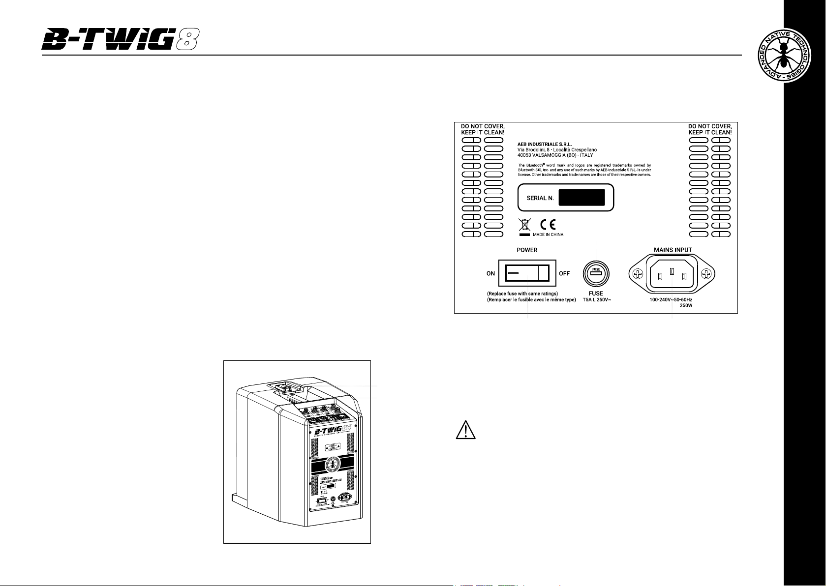
3.2 | POWER SUPPLY
2
16 SLIDE LOCKING SYSTEM FOR QUICK CONNECTION
This mechanism allows coupling and uncoupling support element to the subwoofer
B-TWIG 8S, ensuring a safe perfect functionality.
17 RECESSED HANDLE
Use this top handle for subwoofer carrying
and positioning. Do not use it to hang the
cabinet or to lock it in any position.
User manual | B-TWIG 8
6
16
17
3 1
1 MAINS INPUT
IEC mains socket with integrated EMI lter. Insert the mains cable into
this socket, but make sure the device is switched off before connecting
the cable to the mains. For your safety, never disconnect the earth lead.
2 FUSE
Protection fuse.
CAUTION: Replace the fuse only with one of the same type and with
the same value. If the fuse blows repeatedly, contact an authorized
service center.
3 POWER ON/OFF
Use this switch to turn ON/OFF the unit.
B-TWIG 8 | User manual
ENGLISH
7
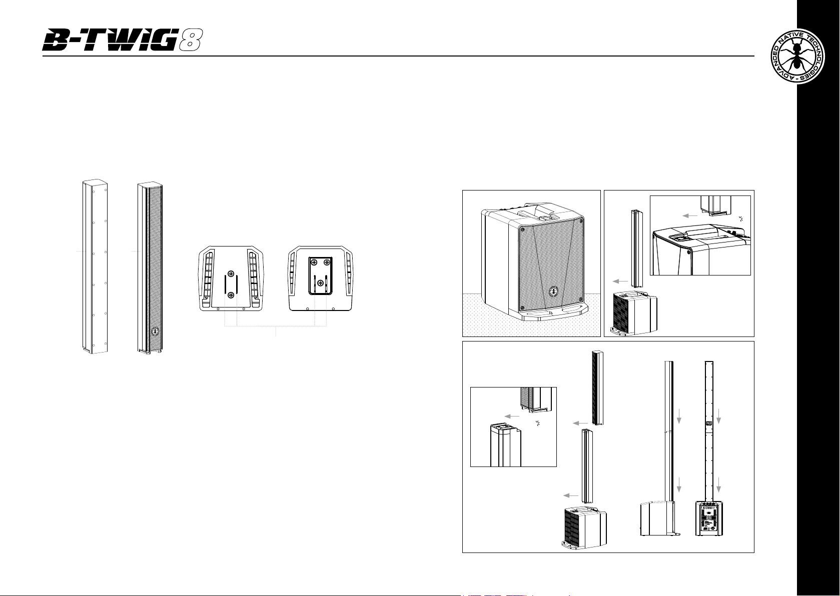
3.3 | B-TWIG 8CS KIT
ASSEMBLY
The kit, supplied of its carrying bag, is composed of two column elements: a stand (A
element) and a speaker (B element). Both are equipped with the slide locking system,
which allows the coupling and the quick release of the elements that make up the
system, ensuring a safe perfect functionality.
Top view
Plug Side Socket Side
A B
Audio Contacts
4 | INSTRUCTIONS FOR SYSTEM ASSEMBLY AND DISASSEMBLY
For system installation and to guarantee the correct operation, always carefully respect
following instructions:
• Place the subwoofer in a vertical position on a flat and stable surface, making
sure that all the rubber feet are perfectly adherent to the floor or to the supporting
surface.
• Never install the system on mobile trolleys, chairs, tables or similar surfaces which
are not stable and cannot support the weight.
• Don’t use the handle to fly the system.
• Do not cover the ventilation slots located on subwoofer rear cabinet.
• To allow proper amplication heat dissipation, please leave the right distance
between the rear panel of the subwoofer and other objects such as walls, corners,
curtains. Never place the unit near heat sources of any kind.
• Place the subwoofer on a flat surface (Fig.1)
• Fix the A element, by sliding it into the sliding mechanism (Fig.2)
• Repeat step 2 to x the element B to the top of the system (Fig.3).
Fig.1
Fig.3
B
Click
A
Hook B by pushing
towards arrow direction
A
Fig.2
A
B
Final assembly
A
Click
Hook A by pushing
towards arrow direction
Side
View
Rear
View
ENGLISH
User manual | B-TWIG 8
8
B-TWIG 8 | User manual
9
 Loading...