

Page 1
POWERED COLUMN SYSTEM
SISTEMA ATTIVO A COLONNA
EN USER MANUAL | Section 1
IT MANUALE D’USO | Sezione 1
Page 2
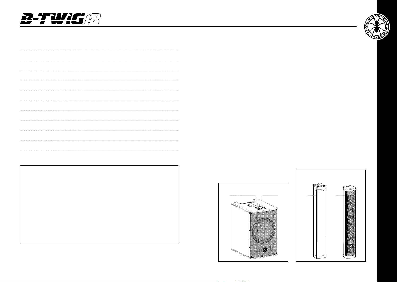
TABLE OF CONTENTS
1 | Introduction 3
2 | Installation 3
3 | Description 4
3.1 | Inputs & controls 4
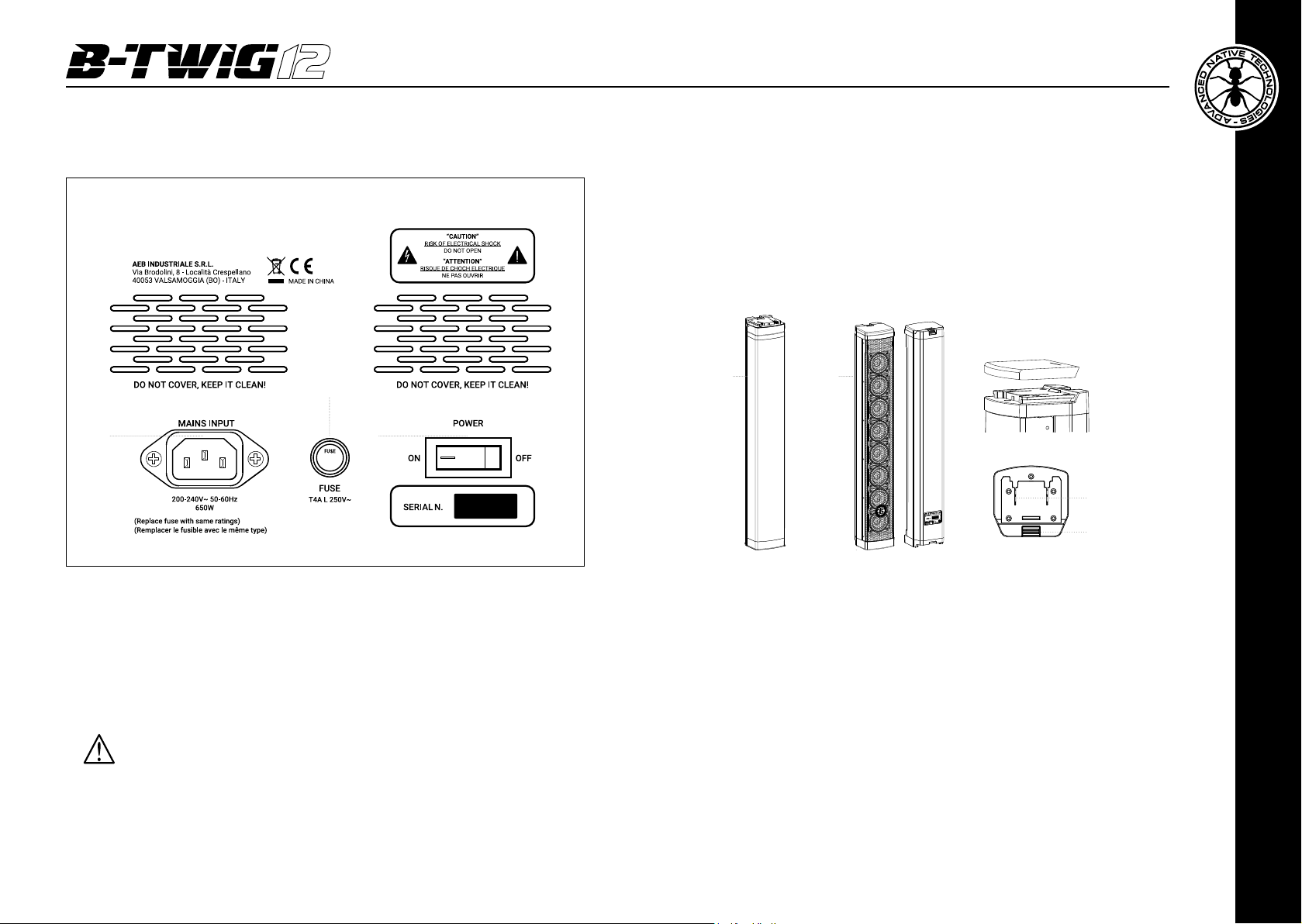
3.2 | Power supply section 6
3.3 | B-TWIG 12CS kit 7
1 | INTRODUCTION
Thank you for choosing a A.N.T – Advanced Native Technologies – product!
In B-TWIG 12 column system we have put our passion and our technological
background gained over the years, to offer products that meet your needs,
maintaining the quality over time.
Specifically designed for an immediate and user-friendly application,
meeting the needs of those who are looking for an audio system delivering
excellent performances, high connection versatility as well as the best value
in its category.
Please, dedicate some minutes to read this instruction manual in order to
quickly achieve the best performances from this product.
For safety precautions, warranty and disposal, please refer to attached Section 2.
4 | Instructions for system assembly and disassembly 7
5 | Troubleshooting 10
6 | Technicalspecications 11
7 | Notes 22
PACKAGE CONTENT
• 1x B-TWIG 12S active subwoofer
• 1x B-TWIG 12CS kit, including:
n.1 support element
n.1 array speaker
n.1 transport bag
• 1x Mains cable (VDE)
• 1x User manual - Section 1
• 1x User manual - Section 2
The warnings in this manual must be observed together with
the “USER MANUAL - SECTION 2”.
For further information about all A.N.T products catalog, please visit our
website: www.ant-sound.com
2 | INSTALLATION
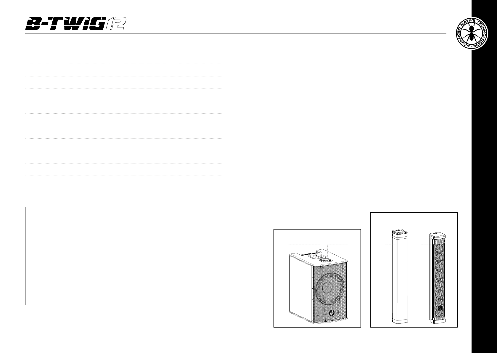
The system is composed by the sub B-TWIG 12S, plus B-TWIG 12CS kit:
A | Top recessed handle
B | Slide locking system for elements quick lock and release
C | Support element
D | Passive array speaker
B-TWIG 12CS
B-TWIG 12S
BA
DC
ENGLISH
User manual | B-TW I G 12
2
B-TW I G 12 | User manual
3
Page 3
3 | DESCRIPTION
1
2 3
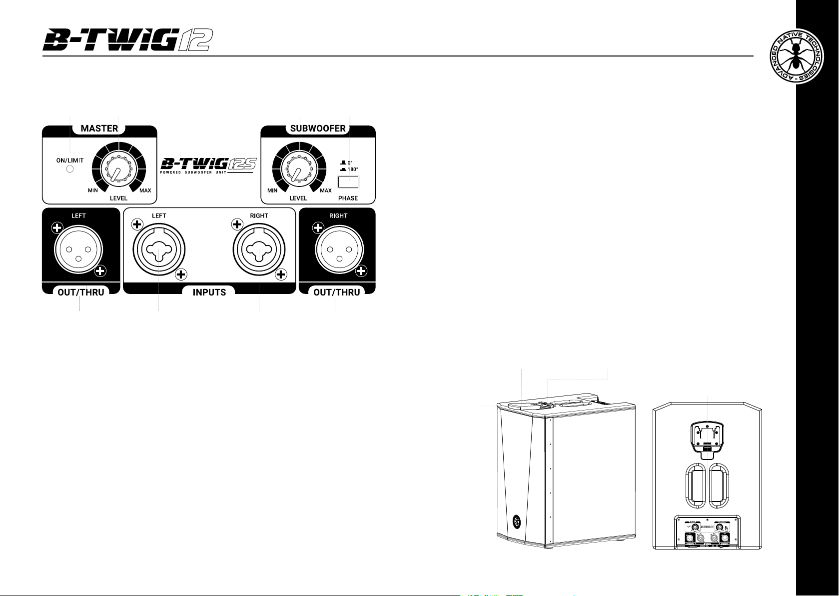
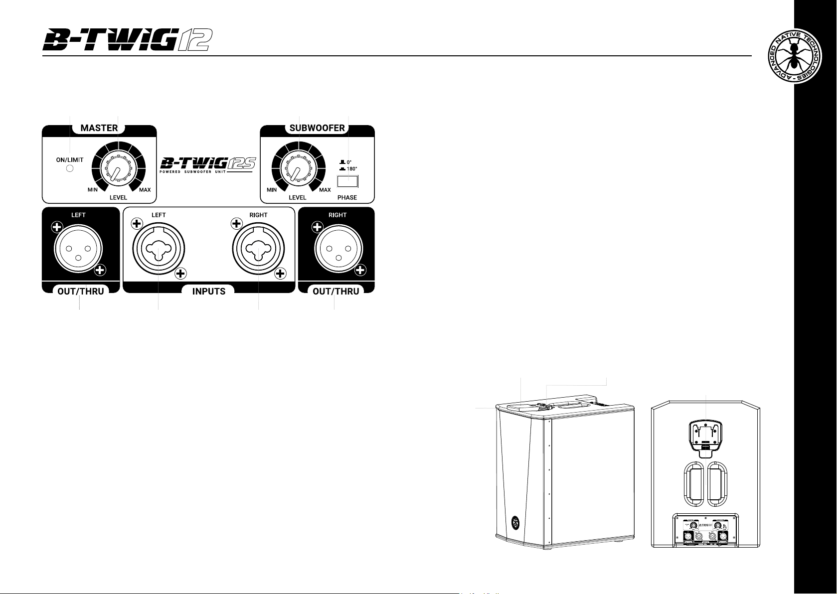
5 LEFT OUT/THRU
XLR-M balanced output to link the IN LEFT input signal to another active
4
system.
6 COMBO LEFT INPUT
Left channel balanced input with Combo
(XLR-F + Unbalanced 6.35mm – 1/4” - jack) connector.
7 COMBO RIGHT INPUT
Right channel balanced input with Combo
(XLR-F + Unbalanced 6.35mm – 1/4” - jack) connector.
8 RIGHT OUT/THRU
XLR-M balanced output to link the IN RIGHT input signal to another active
system.
9 SLIDE LOCKING SYSTEM FOR QUICK CONNECTION
This mechanism allows coupling and uncoupling support element to the
subwoofer B-TWIG 12S, ensuring a safe perfect functionality.
The included cover protects the internal contacts from moisture and dust.
5
6 7 8
3.1 | INPUTS & CONTROLS
1 ON/LIMIT LED
LED LIT GREEN: the unit is plugged in and the power switch is turned ON.
LED LIT RED: indicates the activation of the internal limiter circuit preventing amplier
distortion and protecting the speakers against overloads. In this case, reduce the
MASTER level signal and that of the sound source.
2 MASTER LEVEL
This control adjusts the output level of the system. Turn the knob clockwise to
increase volume, or counterclockwise to decrease it
3 SUBWOOFER LEVEL
This control adjusts the output volume of the subwoofer and allows you to balance
the level of low frequencies, depending on environment acoustic response. Turn the
knob clockwise to increase volume, or counterclockwise to lower it.
4 PHASE 0°-180°
Press this button to reverse of 180 degrees the subwoofer phase.
User manual | B-TW I G 12
4
10 RECESSED HANDLE
Use this top handle only for subwoofer carrying and positioning.
Do not use it to hang the cabinet or to lock it in any position.
Protective cover Release button
10
9
B-TW I G 12 | User manual
ENGLISH
5
Page 4
3.2 | POWER SUPPLY 3.3 | B-TWIG 12CS KIT
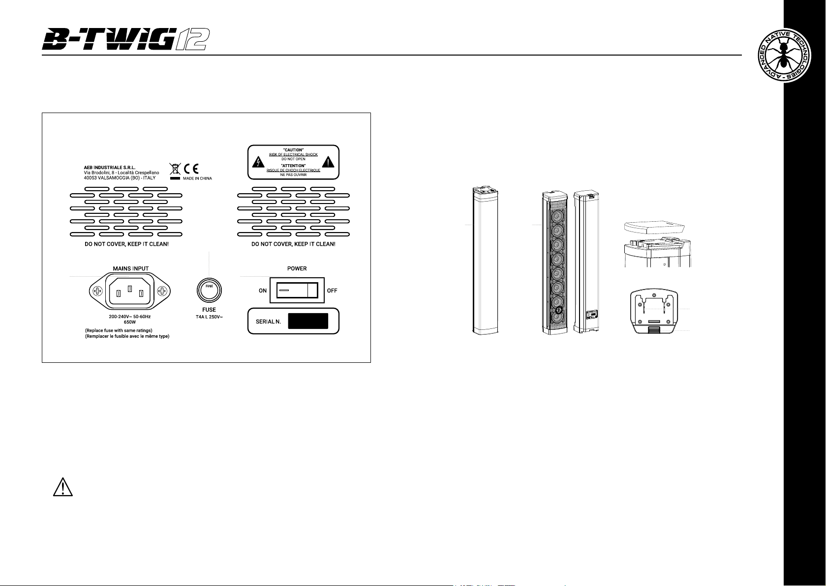
The kit, supplied of its carrying bag, is composed of two column elements:
a stand (A element) and a speaker (B element). Both are equipped with the
slide locking system, which allows the coupling and the quick release of the
elements that make up the system, ensuring a safe perfect functionality.
The included cover protects the internal contacts from moisture and dust in
case of non-use of the system.
A
2
B
Protective cover
1
3
1 MAINS INPUT
IEC mains socket with integrated EMI lter. Each package is supplied with the power
cord for your area. Insert the mains cable into this socket, but make sure the device
is switched off before connecting the cable to the mains. For your safety, never
disconnect the earth lead.
2 FUSE
Protection fuse.
CAUTION: Replace the fuse only with one of the same type and with the same
value. If the fuse blows repeatedly, contact an authorized service center.
3 POWER ON/OFF
Use this switch to turn ON/OFF the unit.
User manual | B-TW I G 12
6
Top view
Audio connections
Release button
4 | INSTRUCTIONS FOR SYSTEM
ASSEMBLY AND DISASSEMBLY
For system installation and to guarantee the correct operation, always
carefully respect following instructions:
• Install the subwoofer in a vertical position on a flat and stable surface,
making sure that all the rubber feet are perfectly adherent to the floor or
to the supporting surface
• Never install the system on mobile trolleys, chairs, tables or similar surfaces
which are not stable and cannot support the weight.
• To allow proper amplication heat dissipation, please leave the right distance
between the rear panel of the subwoofer and other objects such as walls,
corners, curtains. Never place the unit near heat sources of any kind.
• Do not cover the ventilation slots located on subwoofer rear cabinet.
B-TW I G 12 | User manual
ENGLISH
7
Page 5
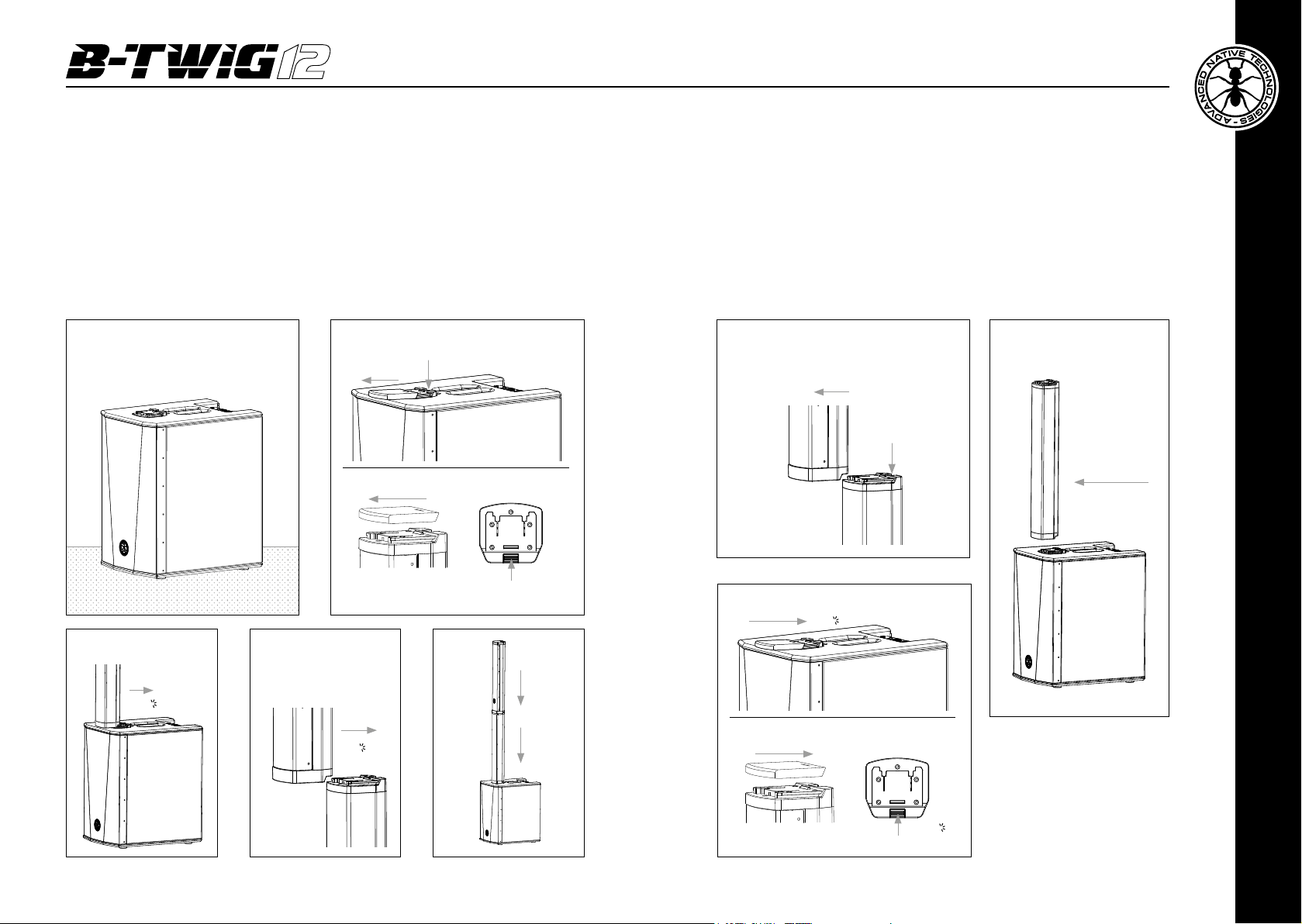
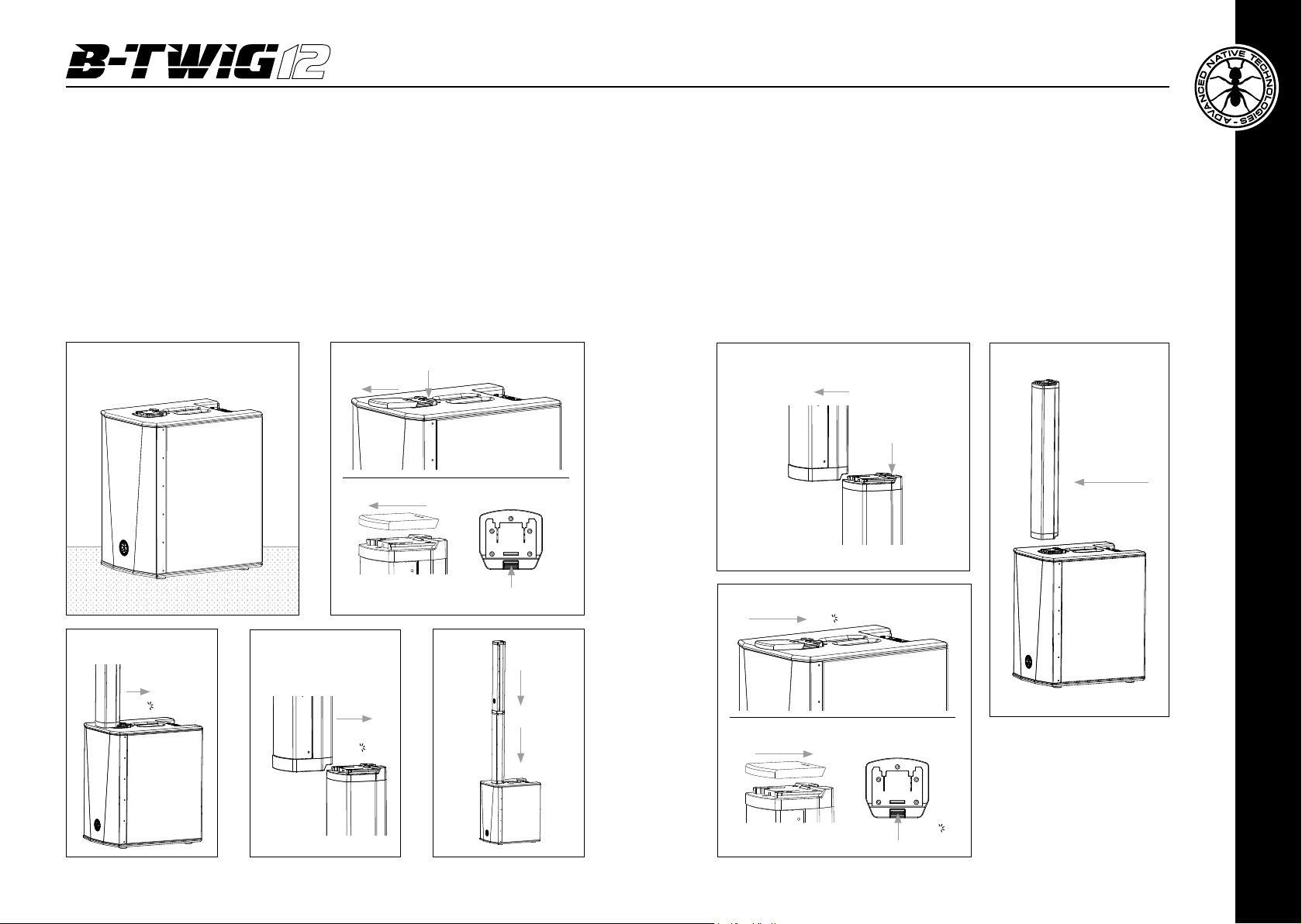
ASSEMBLY
DISASSEMBLY
• Place the subwoofer on a flat surface (g.1)
• Remove the protective covers from the subwoofer and A-B elements locking
mechanism (g.2)
• Fix the A element, by sliding it into the locking mechanism (g.3), xing is achieved
by means of a spring button placed behind the fastening mechanism
• Repeat step 3 to x the element B to the top of the system (g.4) and complete the
installation (g.5)
Fig 1
Fig 3 Fig 4
Lock A toward
the direction
of the arrow
A
Click
B
Fig 2
Lock B toward
the direction
of the arrow
Click
Press the release button
and slide off the cover
Top viewSlide off the cover
A-B Press the
release button
Fig 5
B
A
• Press element B release button, and push forward to release it from the
element A (g.6)
• Repeat the operation to unlock element A from the subwoofer cabinet
(fig.7)
• Restore the slide protective covers on subwoofer and A-B elements locking
system (g. 8)
Fig 6
Unlock B toward
the direction
of the arrow
Press
B
the release
button
A
Fig 8
Restore the cover
Click
Restore the cover Top view
Fig 7
Press the
release button
and unlock A
toward
the direction
of the arrow
A
User manual | B-TW I G 12
8
A
A-B Release button
Click
B-TW I G 12 | User manual
ENGLISH
9
9
Page 6
6 | TECHNICAL SPECIFICATIONS5 | TROUBLESHOOTING
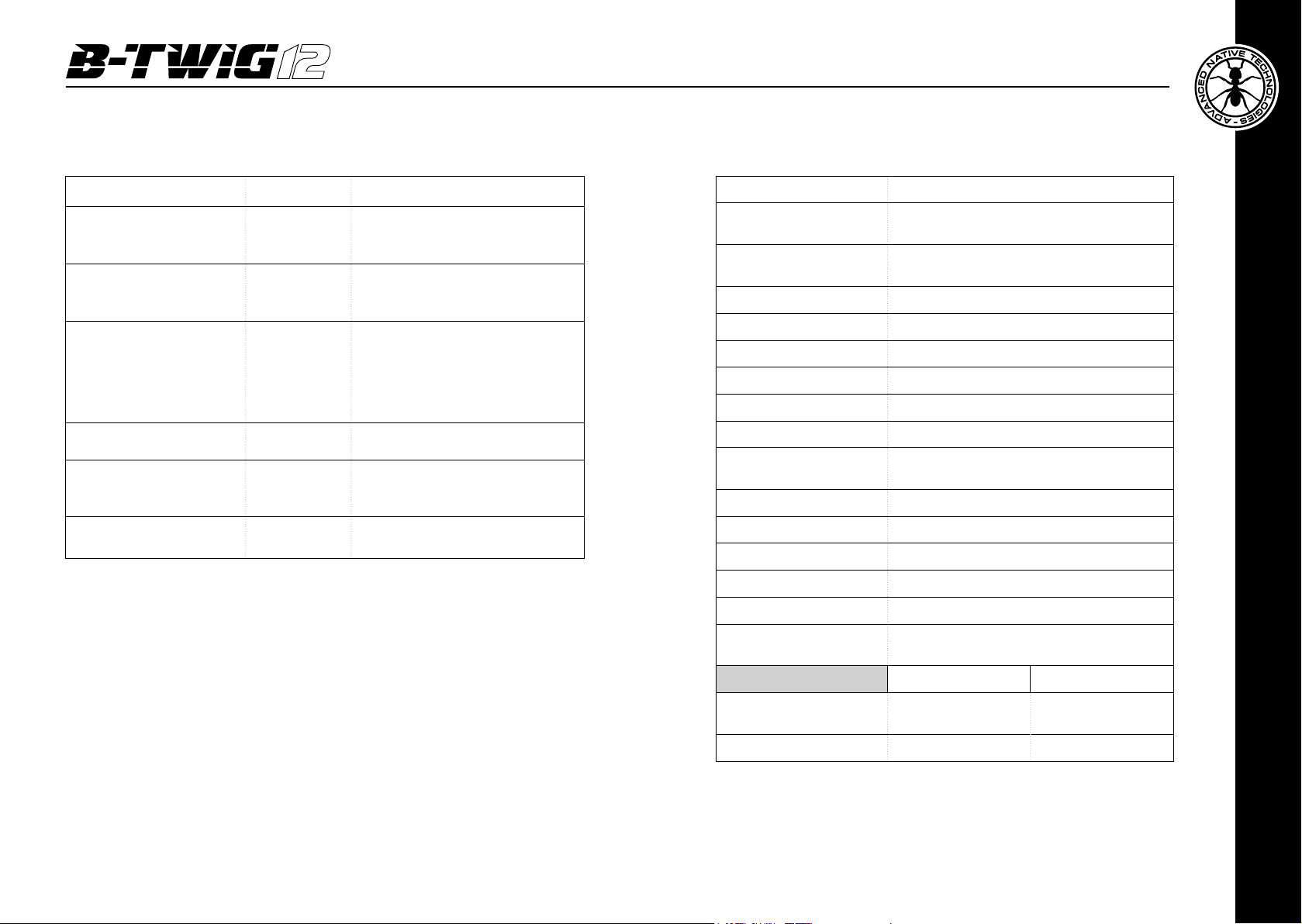
PROBLEM LEDS SOLUTION
No sound or very
low sound level
Power LED turned on,
but low MASTER VOL
Distortion
Booming sound Lower SUBWOOFER level
Harsh sound
Lower frequencies
small attenuation
Power LED
turned off
ON/LIMIT
LED lit red
ON/LIMIT
LED lit green
Make sure the device is properly
connected to the mains outlet
Raise MASTER VOL level
Lower MASTER level
Check the source level
Check proper connection between
subwoofer and A/B elements
Raise SUBWOOFER level
Lower MASTER level
Try reversing subwoofer
phase by pressing the PHASE switch
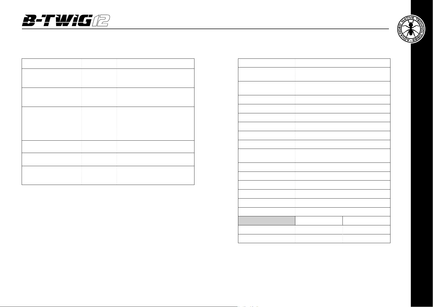
System type Active column system
Subwoofer
(B-TWIG 12S)
Array speaker
(B-TWIG 12CS)
Average dispersion Horizontal 120°
Frequency response 45Hz - 20kHz
SPL - MAX 123 dB
Amplier Class D
Peak Power (LF+HF) 2000 W
Crossover 24dB/Oct @ 200Hz
I/O connectors
Controls Master Level, Subwoofer Level, Phase 0°/180°
Power supply 200-240V~ 50-60Hz
Fuse T4A L 250V~
Fastening mechanism Custom slide connector with automatic lock
Cabinet 12mm plywood
Surface nishing
1 x 12” custom speaker - 2.5” V.C
8 x 2.75” Neo custom speakers - 0.75” V.C
LINE IN: 2 x Combo XLR-F + Jack 6,35mm (1/4”)
OUT/THRU: 2 x XLR-M
Scratch-resistant coating with high mechanical
resistance
User manual | B-TW I G 12
10
B-TWIG 12S B-TWIG 12CS
Dimensions (W x H x D)
Weight 19 kg – 41.2 lbs 4.6 kg - 10.1 lbs
370 x 603 x 505mm
14.6” x 23.7” x 19,9”
105 x 707 x 100mm
4.1” x 28.8” x 3.9”
EMI CLASSIFICATION
According to the standard EN55103 this equipment is designed and suitable
to operate in E3 (or lower E2, E1) electromagnetic environments.
B-TW I G 12 | User manual
ENGLISH
11
Page 7
INDICE
1 | Introduzione 13
2 | Installazione 13
3 | Descrizione 14
3.1 | Ingressi & controlli 14
3.2 | Alimentazione 16
3.3 | Kit B-TWIG 12CS 17
4 | Istruzioni di montaggio e smontaggio del sistema 17
5 | Soluzione dei problemi 20
6 | Caratteristiche tecniche 21
7 | Note 22
CONTENUTO DELL’IMBALLO
1 | INTRODUZIONE
Grazie per aver acquistato un prodotto A.N.T – Advanced Native Technologies!
Nel sistema array B-TWIG 12 abbiamo profuso la nostra passione ed il nostro
know-how maturato nel corso degli anni per offrirvi un prodotto che soddis le
vostre esigenze e mantenga la sua qualità nel tempo.
Progettato appositamente per un utilizzo estremamente immediato e semplice,
risponde alle esigenze di quanti desiderano un sistema audio in grado di fornire
ottime prestazioni, versatilità di connessioni e il miglior rapporto qualità/prezzo
possibile nella sua categoria.
Ritagliatevi qualche minuto per leggere questo manuale di istruzioni in modo
tale da ottenere rapidamente il massimo delle performance da questo prodotto.
Per le istruzioni relative a sicurezza, le precauzioni, la garanzia e lo smaltimento
fate riferimento all’allegato sezione 2.
Per ulteriori informazioni su tutti i prodotti del catalogo A.N.T consultate il nostro
sito: www.ant-sound.com
2 | INSTALLAZIONE
Il sistema è composto dal sub B-TWIG 12S e dal kit B-TWIG 12CS:
A | Maniglia superiore incassata
B | Connettore a slitta di attacco e sgancio rapido degli elementi
C | Elemento di sostegno
D | Diffusore passivo a colonna
B-TWIG 12CS
• 1x Sub attivo B-TWIG 12S
• 1x Kit B-TWIG 12CS comprendente:
n.1 elemento di sostegno
n.1 diffusore a colonna
n.1 custodia da trasporto
• 1x Cavo di alimentazione (VDE)
• 1x Manuale d’uso - Sezione 1
• 1x Manuale d’uso - Sezione 2
Le avvertenze nel presente manuale devono essere osservate
congiuntamente al “MANUALE D’USO - SEZIONE 2”.
Manuale d’uso | B-T WIG 12
12
B-TWIG 12S
DCBA
B-TWIG 12 | Manuale d’uso
ITALIANO
13
Page 8
3 | DESCRIZIONE
1
5
2 3
6 7 8
4
3.1 | INGRESSI & CONTROLLI
1 INDICATORE BICOLORE ON/LIMIT
LED VERDE: l’apparecchio è collegato alla rete elettrica e l’interruttore di accensione
è commutato su ON.
LED ROSSO: Indica l’intervento del circuito limitatore interno, che evita la distorsione
dell’amplicatore e protegge gli altoparlanti contro i sovraccarichi. In questo caso
riducete il segnale MASTER e quello della sorgente sonora.
5 LEFT OUT/THRU
Uscita XLR-M bilanciata per il rilancio del segnale in ingresso LEFT IN
ad un altro sistema amplicato.
6 COMBO LEFT INPUT
Ingresso bilanciato per il canale di sinistra con presa Combo
(XLR-F + jack bilanciato da 6,35mm)
7 COMBO RIGHT INPUT
Ingresso bilanciato per il canale di destra con presa Combo
(XLR-F + jack bilanciato da 6,35mm)
8 RIGHT OUT/THRU
Uscita XLR-M bilanciata per il rilancio del segnale in ingresso RIGHT IN
ad un altro sistema amplicato.
9 SISTEMA DI CONNESSIONE RAPIDO DEGLI ELEMENTI
Questo meccanismo permette l’aggancio e lo sgancio dell’elemento di
sostegno al subwoofer B-TWIG 12S, assicurandone la perfetta funzionalità
in tutta sicurezza. Il coperchio in dotazione consente di proteggere i
contatti interni da umidità e polvere.
10 MANIGLIA INCASSATA
Utilizzate questa maniglia solo per il trasporto ed il posizionamento del
subwoofer. Non usatela per appendere il subwoofer o per bloccarlo in
qualsiasi posizione.
Coperchio di protezione Pulsante di rilascio
10
9
2 MASTER LEVEL
Questo controllo regola il volume di uscita del sistema. Girate la manopola in senso
orario per aumentare il volume o in senso antiorario per abbassarlo.
3 SUBWOOFER LEVEL
Questo controllo regola il volume di uscita del subwoofer e permette di bilanciare
il livello di frequenze basse in base alla risposta acustica dell’ambiente. Girate la
manopola in senso orario per aumentare il volume o in senso antiorario per abbassarlo.
4 PHASE 0°-180°
Premete questo tasto per invertire la fase del subwoofer di 180°.
Manuale d’uso | B-T WIG 12
14
B-TWIG 12 | Manuale d’uso
ITALIANO
15
Page 9
3.2 | ALIMENTAZIONE 3.3 | KIT B-TWIG 12CS
Il kit, fornito dell’apposita custodia di trasporto, è composto da due elementi a
colonna: uno stativo (elemento A) e un diffusore (elemento B). Entrambi sono
dotati del meccanismo di connessione a slitta, che permette l’aggancio e lo
sgancio rapido degli elementi che compongono il sistema, assicurandone
la perfetta funzionalità in tutta sicurezza.
Il coperchio in dotazione consente di proteggere i contatti interni da umidità
e polvere in caso di non utilizzo prolungato del sistema.
Coperchio di protezione
2
1 3
1 MAINS INPUT
Presa IEC di ingresso con ltro di rete integrato. Ogni confezione è fornita del cavo
di alimentazione necessario, specico per la vostra zona. Inserite in questa presa
il cavo per l’alimentazione elettrica ma accertatevi che l’apparecchio sia spento
prima di collegare il cavo alla rete. Per la vostra sicurezza, non scollegate mai il polo
centrale di terra.
2 FUSE
Fusibile di protezione.
ATTENZIONE: Sostituite il fusibile unicamente con uno dello stesso tipo e
con gli stessi valori. Se il fusibile continua a saltare rivolgetevi ad un centro
di assistenza autorizzato.
3 POWER ON/OFF
Interruttore per l’accensione e lo spegnimento dell’apparecchio.
A B
Vista superiore
Contatti audio
Pulsante di rilascio
4 | ISTRUZIONI DI MONTAGGIO E SMONTAGGIO DEL SISTEMA
Per l’installazione degli apparecchi e a garanzia del loro corretto funzionamento,
attenetevi scrupolosamente alle seguenti istruzioni:
• Collocate il subwoofer in posizione verticale su una supercie piana e stabile,
assicurandovi che tutti i piedini inferiori in gomma siano perfettamente
aderenti al pavimento o alla supercie di appoggio.
• Non installate mai il sistema su carrelli mobili, sedie, tavoli o oggetti simili
che non siano stabili o in grado di sopportare il peso.
• Per consentire una corretta dissipazione del calore dell’amplicazione,
lasciate una distanza sufciente tra il panello posteriore del subwoofer e
altri oggetti quali pareti, angoli, tende. Non posizionate mai l’apparecchio
vicino sorgenti di calore di qualsiasi tipo.
• Non ostruite mai le feritoie di aerazione collocate sul telaio posteriore del
subwoofer.
ITALIANO
Manuale d’uso | B-T WIG 12
16
B-TWIG 12 | Manuale d’uso
17
Page 10
INSTALLAZIONE
DISINSTALLAZIONE
• Collocate il subwoofer su una supercie piana e priva di ogni dislivello (g.1)
• Rimuovete i coperchi di protezione dal meccanismo di aggancio del subwoofer
e dagli elementi A-B (g.2)
• Assicurate l’elemento A facendolo scorrere nel meccanismo di aggancio a slitta (g.3),
il ssaggio avviene per mezzo di un pulsante a molla collocato dietro al meccanismo
di aggancio.
• Ripetete l’operazione per ssare l’elemento B nella parte superiore (g.4) ultimando
l’installazione del sistema (g.5)”
Fig 1
Fig 3 Fig 4
Agganciare A
verso il senso
della freccia
A
Click
B
Fig 2
Agganciare B
verso il senso
della freccia
Click
Premere il pulsante di rilascio
ed estrarre il coperchio
Vista superioreEstrarre il coperchio
A-B Pulsante di rilascio
Fig 5
B
A
• Premete sul pulsante di rilascio dell’elemento B e spingete in avanti per
sganciarlo dallo stativo A (g.6)
• Ripetete l’operazione per sganciare l’elemento A dal subwoofer (g.7)
e ultimare lo smontaggio del sistema
• Riponete i coperchi di protezione sui meccanismi di aggancio del subwoofer
e degli elementi A-B (g. 8)
Fig 6
Sganciare B verso
il senso dalla freccia
B
Fig 8
Riporre il coperchio
Riporre il coperchio
Premere
il pulsante
di rilascio
A
Click
Vista superiore
Fig 7
Premere il
pulsante di
rilascio e
sganciare A
verso il senso
della freccia
A
User manual | B-TW I G 12
A
Click
A-B Pulsante di rilascio
B-TWIG 12 | Manuale d’uso
19 18
19
ITALIANO
Page 11
6 | CARATTERISTICHE TECNICHE5 | SOLUZIONE DEI PROBLEMI
PROBLEMA SPIE SOLUZIONE
Assenza di suono o suono
troppo basso
LED Power acceso
ma MASTER VOL abbassato
Distorsione
Suono risonante Attenuate il livello SUBWOOFER
Suono stridente Abbassate il livello MASTER
Lieve attenuazione
delle frequenze basse
LED Power
spento
Led ON/LIMIT
rosso
Led ON/LIMIT
verde
Assicuratevi che l’apparecchio
sia collegato correttamente
alla presa di corrente
Alzate il livello di MASTER VOL
Attenuate il livello del MASTER
Controllate il livello della sorgente
Controllate la perfetta connessione
fra subwoofer e gli elementi A/B
Provate ad invertire la fase
del subwoofer premendo
l’interruttore PHASE
Tipo Sistema a colonna amplicato
Subwoofer
(B-TWIG 12S)
Diffusore a colonna
(B-TWIG 12CS)
Dispersione media 120° orizzontale
Risposta in frequenza 45Hz - 20kHz
SPL - MAX 123 dB
Amplicatore Classe D
Potenza di picco (LF+HF) 2000 W
Crossover 24dB/Oct @ 200Hz
Connettori I/O
Controlli Master Level, Subwoofer Level, Phase 0°/180°
Alimentazione 200-240V~ 50-60Hz
Fusibile T4A L 250V~
Meccanismo di ssaggio Connettore a slitta con aggancio automatico
Materiale cabinet Multistrato da 12mm
Rivestimento cabinet Vernice antigrafo ad alta resistenza meccanica
Cabinet Bass reflex
1 x Altoparlante custom da 12” - 2.5” VC
8 x Altoparlanti custom al neodimio da 2.75” - 0.75” VC
LINE IN: 2 x Combo XLR-F + Jack 6,35mm (1/4”)
OUT/THRU: 2 x XLR-M
Manuale d’uso | B-T WIG 12
20
B-TWIG 12S B-TWIG 12CS
Dimensioni (L x A x P) 370 x 603 x 505mm 105 x 707 x 100mm
Peso 19 kg 4.6 kg
CLASSIFICAZIONE EMI
In accordo alle normative EN55103, l’apparato è progettato e idoneo all’utilizzo
in ambienti elettromagnetici E3 o inferiori (E2, E1).
B-TWIG 12 | Manuale d’uso
ITALIANO
21
Page 12
6 | NOTES/NOTE7 | NOTES/NOTE
www.ant-sound.com
ENG The information contained in this manual have been carefully drawn up and checked.
However no responsibility will be assumed for any incorrectness. This manual cannot cover all
the possible contingencies which may arise during the product installation and use. Should
further information be desired, please contact us or our local distributor. A.E.B. Industriale Srl
can not be considered responsible for damages which may be caused to people and things
whenusingthisproduct.Specicationsandfeaturesaresubjecttochangewithoutpriornotice.
ITA Le informazioni contenute in questo manuale sono state attentamente redatte e
controllate. Tuttavia non si assume alcuna responsabilità per eventuali inesattezze. Questo
manuale non può contenere una risposta a tutti i singoli problemi che possono presentarsi
durante l’installazione e l’uso dell’apparecchio. Siamo a vostra disposizione per fornirvi
eventuali ulteriori informazioni e consigli. A.E.B. Industriale Srl non può essere ritenuta
responsabile per danni o incidenti a cose o persone, causati o connessi all’utilizzazione o
malfunzionamento dell’apparecchio.
Manuale d’uso | B-T WIG 12
22
Made in China
Prodotto in Cina
Page 13

A.E.B. Industriale Srl - Via Brodolini, 8 - Località Crespellano
40053 Valsamoggia - Bologna (ITALIA)
Tel +39 051 969870 - Fax +39 051 969725
©2017 A.E.B. Industriale Srl | Printed in China | REV 1.2
 Loading...