

Ant B-Twig 12 Pro User manual
SECCIÓN 1
ES MANUAL DE USO |
SECTION 1
FR NOTICE D’EMPLOI |
KAPITEL 1
DE BEDIENUNGSANLEITUNG |
POWERED COLUMN SYSTEM
SISTEMA ATTIVO A COLONNA
SYSTÈME ACTIF EN COLONNE
AKTIVES SÄULENSYSTEM
SISTEMA ACTIVO DE COLUMNA
SEZIONE 1
SECTION 1
EN USER MANUAL |
IT MANUALE D’USO |
TABLE OF CONTENTS
1 | Introduction 3
2 | Installation 4
3 | Description 5
1 | INTRODUCTION
Thank you for choosing a A.N.T - Advanced Native Technologies - product!
In B-TWIG 12 PRO column system we have put our passion and our
technological background gained over the years, to offer products that meet
your needs, maintaining the quality over time.
3.1 | Inputs & controls 5
3.2 | Connections 9
3.3 | Power supply section 13
3.4 | B-TWIG 12CS KIT 14
4 | Instructions for system assembly and disassembly 15
5 | Application congurations 18
6 | Troubleshooting 20
7 | Technical specications 21
8 | Notes 23
PACKAGE CONTENT
• 1x B-TWIG 12S PRO active subwoofer, including:
n.1 support element
n.1 mains cord (VDE)
• 1x B-TWIG 12CS PRO kit, including:
n.2 passive column speakers
• 1x User manual - Section 1
• 1x User manual - Section 2
The warnings in this manual must be observed together with the
“USER MANUAL - SECTION 2”.
Specically designed for an immediate and user-friendly application, meeting
the needs of those who are looking for an audio system delivering excellent
performances, high connection versatility as well as the best value in its
category.
Characterized by an elegant and contemporary prole, it optimally combines
great quality professional features and exceptional value such as:
• Internal DSP with 4 equalization presets;
• Integrated DFX unit featuring 16 presets, with sends and return level
included;
• 4CH mixer with multiple I/O combinations and Bluetooth® connection;
• Acoustic solutions optimized to guarantee excellent sound quality in a
wide range of frequencies;
• Exclusive mechanism for 90 degrees rotation and orientation of the
columns, which can be used to direct the acoustic coverage according
to the needs of use and installation as well as system positioning
For a easier and more immediate use of the product, several optional
accessories are available.
Please, dedicate some minutes to read this instruction manual in order to
quickly achieve the best performances from this product.
For safety precautions, warranty and disposal, please refer to attached
Section 2.
For further information about all A.N.T products catalog, please visit our
website: www.ant-intomusic.com
ENGLISH
User manual | B-TWIG 12 PRO
2
B-TWIG 12 PRO | User manual
3

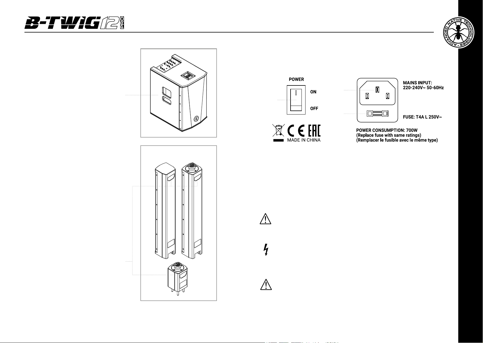
2 | INSTALLATION
The system is composed by the active subwoofer B-TWIG 12S PRO,
plus B-TWIG 12CS PRO kit:
A | Side recessed handle.
B | Pins system for elements quick lock and release.
C | Support element.
D | Passive array speakers, with rear recessed handles.
E | Anti-slip rubber feet.
F | Built-in fastening points for transport wheels xing.
B-TWIG 12S PRO B-TWIG 12CS PRO
DA B
B
E
3 | DESCRIPTION
2
3
1 5
6
7
8
9
A
User manual | B-TWIG 12 PRO
4
E CF
B
D
4
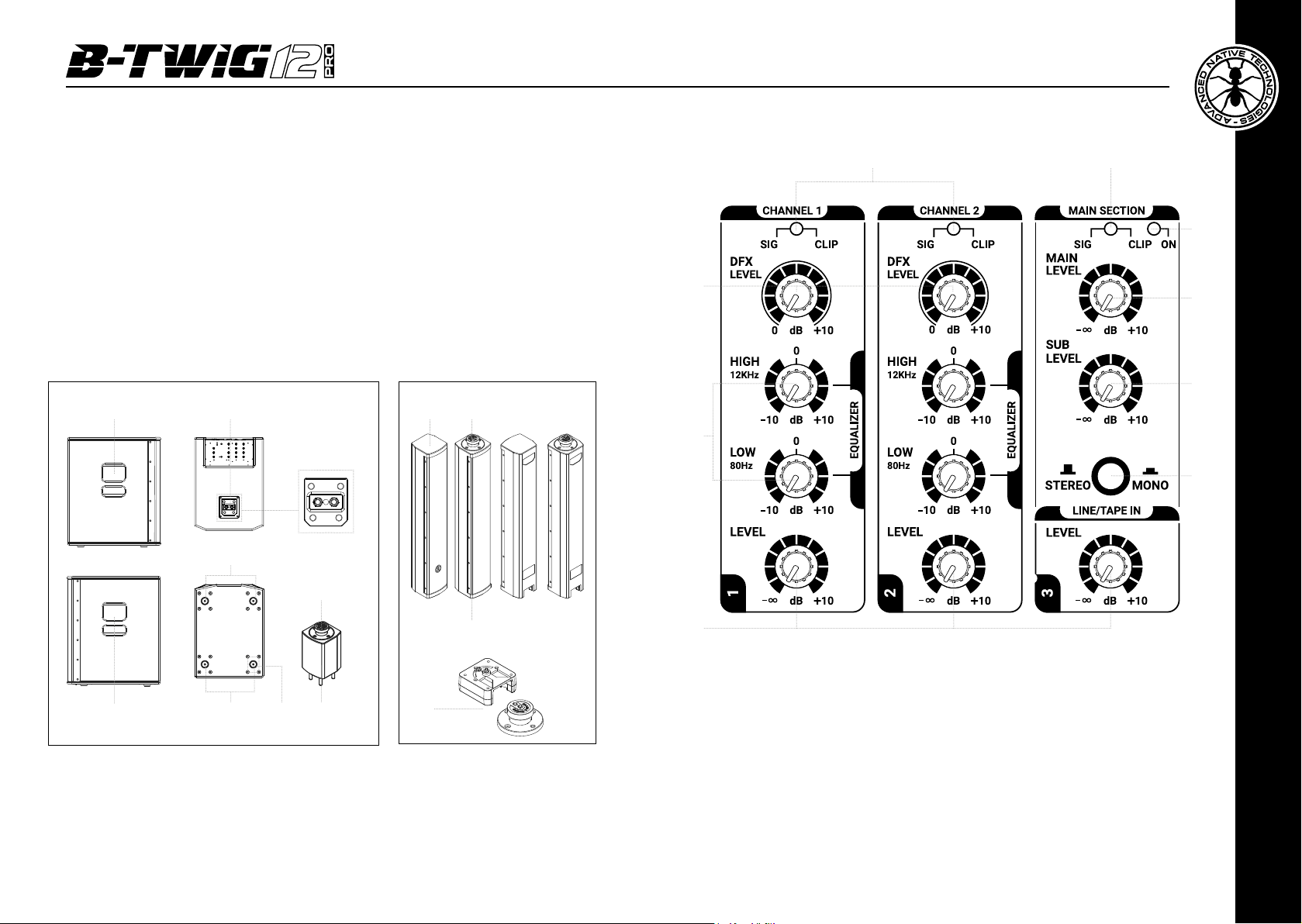
3.1 | INPUTS & CONTROLS
B
1 CH1 / CH2 - TWO-TONE SIG/CLIP LED
Green: The unit is plugged in and the power switch is turned ON.
Red: The input signal is very high and close to distortion.
If the LED is steadily lit, you need to reduce the input signal or adjust the
channel EQ by reducing the boost introduced by the HIGH and LOW gains.
2 CH1 / CH2 - DFX LEVEL
This send, affected by the level control of each single channel, allows to
adjust the signal sent to the DFX internal effects unit.
ENGLISH
B-TWIG 12 PRO | User manual
5
3 CH1 / CH2 - EQUALIZER
This two-band equalizer allows you to boost or cut the high and/or low frequencies, to
achieve the desired sound.
4 CH1 / CH2 / LINE/TAPE IN - LEVEL
These knobs adjust the volume of the corresponding channel, turn them to the right to
raise the level, to the left to decrease it.
5 MAIN SECTION - TWO-TONE SIG/CLIP LED
Green: the signal is present in the MAIN channel.
Red: the input signal to the MAIN is very strong and is close to distortion.
If the LED is steadily lit, you must reduce the MAIN LEVEL level or adjust differently level
of CH1 / CH2 / LINE/TAPE IN and AUX.
6 ON
The LED is lit when the unit is connected to the mains and the switch is set to ON.
7 MAIN LEVEL
This control adjusts the overall output volume of the system. Turn the knob clockwise
to increase the volume or counter-clockwise to lower it.
8 SUB LEVEL
This control adjusts the output volume of the subwoofer and allows you to balance
the level of lower frequencies, based on environment acoustic response. Turn the knob
clockwise to increase the SUB volume or counterclockwise to lower it.
9 STEREO / MONO BUTTON
It allows to select the system listening conguration in two operating modes: STEREO
or MONO.
- Set the button to MONO when using a single B-TWIG 12 PRO system; in this case all
the stereo signals of the inputs are internally summed. You can connect an additional
unit via the MIX OUT MONO (L/R) output, thus duplicating the sound front.
- Set the button to STEREO when using two B-TWIG 12 PRO systems; in this case all
the stereo signals of the inputs are mixed in LEFT / RIGHT and simultaneously managed
with the respective systems as follows:
the left channel (L) of all stereo inputs is reproduced by the main unit, while the right
channel (R) of all stereo inputs is reproduced by the additional unit connected to the
MIX OUT STEREO (R) output.
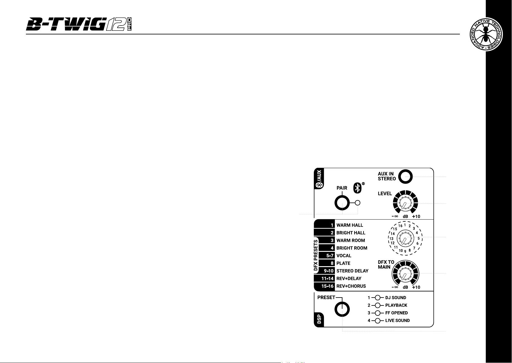
10 PAIR - BUTTON & LED
Use this button to synchronize the Bluetooth® device with the system applying the
following procedure:
• press the PAIR button for about 3 seconds until when the LED rhythmically flashes;
• to start synch, activate Bluetooth® from the user interface of your mobile device;
• in your smartphone or tablet list of devices detected, select "B-TWIG 12 PRO" to
synchronize your mobile device with the system.
At the end of the operation the LED is steadily lit and the tracks can be
played back, as long as device maximum distance from the unit does not
exceed 10 meters.
The Bluetooth
®
connection can be deactivated at any time by holding down
the PAIR button for 3 seconds or by desyncing the B-TWIG 12 PRO unit from
the mobile device. In both cases, the indicator light flashes slowly every 5
seconds, indicating that the connection has been deactivated.
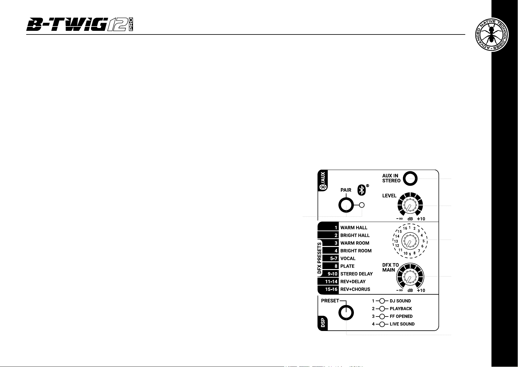
11 AUX IN STEREO
This 3.5mm stereo input accepts the cable signal from external devices, such
as a smartphone, tablet, PC or any other device with a stereo mini-jack output.
10
11
12
13
14
15
ENGLISH
User manual | B-TWIG 12 PRO
6
B-TWIG 12 PRO | User manual
7

12 BLUETOOTH® / AUX - LEVEL
This knob adjusts the volume of AUX IN STEREO and BLUETOOTH® inputs, turn the
knob to the right to raise the level, to the left to decrease it.
13 DFX PRESETS
This 16-position selector allows you to choose the desired type of effect.
For a quick reference, the list of effects is shown to the left of the selector.
The rst 4 effects emulate different reverberations, characterized by reflections of the
sound inside two different ambients, the following 4 (5-8) are suggested in particular
for vocal or percussions, the stereo delays generate the classic delay effect of the main
signal, nally there are the multi-effect combinations (11-16) ideal for vocal and most
solo instruments.
14 DFX TO MAIN
This knob determines the overall signal level of the DFX effects unit for the main output.
Use the knob to increase or decrease the amount of processed signals to be send to
the MAIN LEVEL.
15 DSP - PRESET BUTTON AND LED
Press this button to select the equalization suitable for system use.
The lit LED shows the activated preset.
• DJ SOUND
Suitable for installations in disco club or a mobile DJ SET, applications where a punchy
tone is required as well as a predominance of very deep and engaging bass frequencies.
• PLAYBACK
For listening and using reproduced music sources (CD players, MP3, etc.). Low and high
frequencies are emphasized. Suitable for all those situations where the background
music is spread out, even at low volume.
• FF OPENED
This preset optimizes speech intelligibility with an accurate and balanced dynamic
response.
It's particularly suitable for spread of announcements, warnings and vocal messages,
as well as for listening and use of playback music, with both columns set far from the
main listening wavefront.
NOTE
: the FF OPENED preset does not supersede a correct arrangement of the speakers,
nor it acts with different signal output delays on each individual speaker.
• LIVE SOUND
For system use in live performances. Characterized by a flat and realistic response, it
is suitable for concerts in clubs, as well as for musicians and singers.
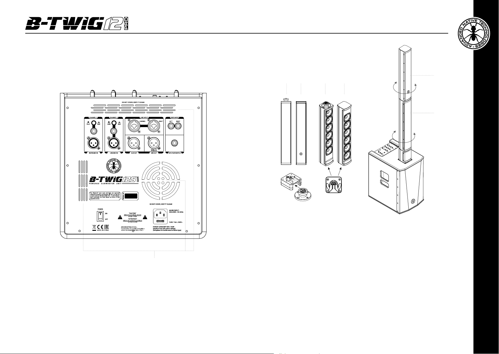
3.2 | CONNECTIONS
1
2
3
1 HI-Z / MIC - CH1 BUTTON
This button switches channel 1 input signal impedance.
Set the button to MIC to connect a microphone or set the button to HI-Z
when you need to connect an electro-acoustic guitar. The button only acts
on the 6.35mm input jack.
2 HI-Z INPUT - CH1
Balanced input with 6.35mm (1/4”) socket. An unbalanced cable can also
be used.
3 MIC INPUT - CH1
Balanced microphone input with XLR-F socket.
4 LINE / MIC - CH2 BUTTON
Set the button to LINE to use a line-level source or set the button to MIC to
use a microphone.
5 LINE INPUT - CH2
Balanced input with 6.35 mm jack. An unbalanced cable can also be used.
6 MIC INPUT - CH2
Balanced microphone input with XLR-F socket.
4
5
6
User manual | B-TWIG 12 PRO
8
B-TWIG 12 PRO | User manual
ENGLISH
9
ATTENTION
: To achieve a balanced and homogeneous stereo sound front,
when connecting two systems in a stereo conguration, set identically the
7
additional system controls (R).
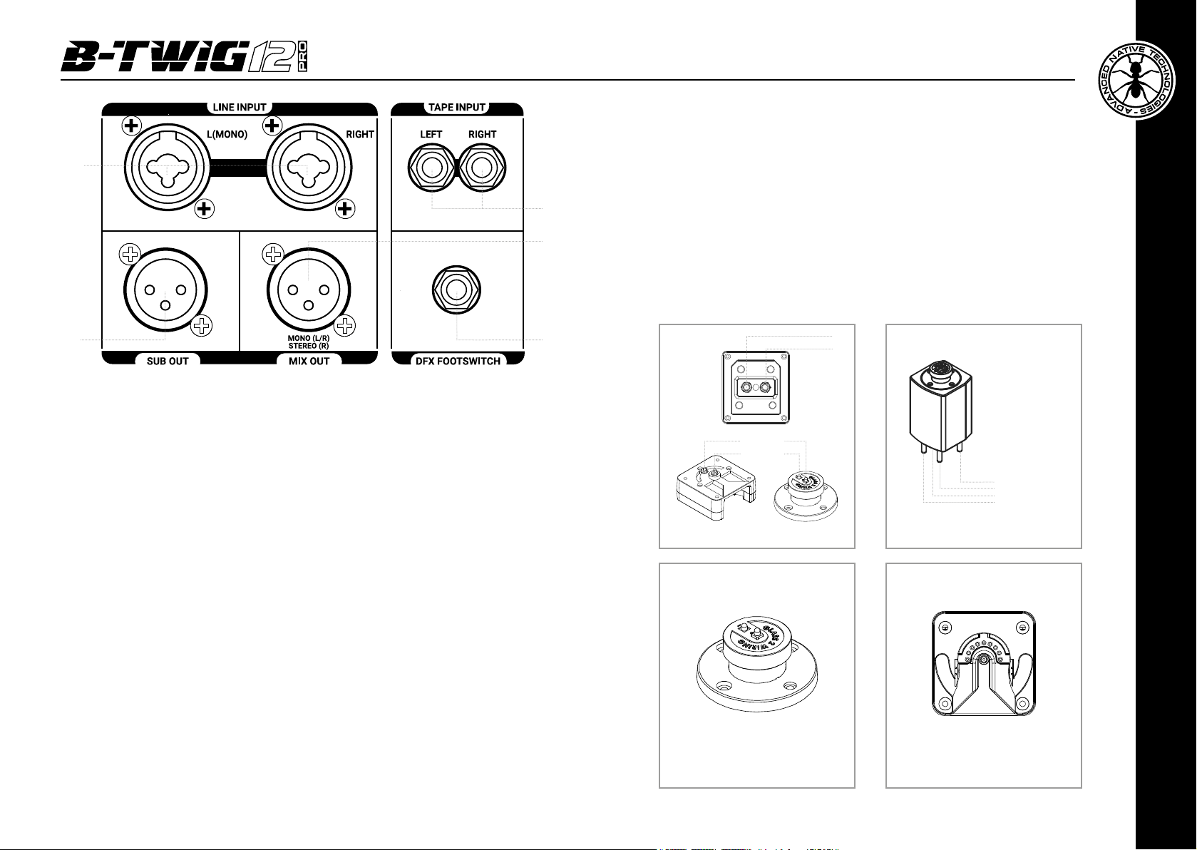
7 LINE INPUT L/R
Balanced line inputs with COMBO sockets (XLR-F + 6.35mm Jack); by connecting a
single cable to the L (MONO) socket, the signal is internally processed as mono. The
volume of these inputs is regulated by channel 3 knob.
8 TAPE INPUT L/R
Unbalanced line input with RCA L/R sockets. Connect to these sockets the output of a
hi- device (CD) or other device with RCA L/R outputs. The volume of these inputs is
controlled by channel 3 knob.
9 SUB OUT
Balanced XLR-M output to send the signal to another active subwoofer. The level is
influenced by both SUB LEVEL and MAIN knobs.
10 MIX OUT L/R - R
Balanced XLR-M output for addressing the MAIN MIX signal to another B-TWIG 12
PRO system.
The output signal is influenced by the position of the STEREO / MONO button, as
described in point 9, chapter 3.1.
Button pressed (MONO): all the signals present in input channels are internally summed
and the MIX OUT provides the signal for an additional reinforcement system.
Button raised (STEREO): the signal present in the left channel (L) of all stereo inputs
is summed and exclusively played back by the main system, while the signal in the
right channel (R) of all stereo inputs is summed and exclusively played back from the
additional system.
NOTE
: The signal of the Mono inputs CH1 and CH2 is reproduced equally on the left
(main system) and on the right (additional system)
8
10
119
11 DFX FOOTSWITCH
Connect to this unbalanced jack an external footswitch for activating or
bypassing internal effects. Press once to deactivate the effects and a second
time to reactivate them.
12 FAST ELEMENTS CONNECTION SYSTEM
This mechanism allows locking and release of the elements that make up
the system, ensuring the perfect functionality in total safety.
+
-
+-
-+
Steel guide
pins
Audio contacts (+ / -)
Circular coupling and
rotation joint (male)
Circular coupling and
rotation joint (female)
ENGLISH
User manual | B-TWIG 12 PRO
10
B-TWIG 12 PRO | User manual
11
13 RECESSED SIDE HANDLES
SUBWOOFER
Use these handles for transporting and
positioning the subwoofer. Do not use them to
fly the subwoofer or to lock it in any position.
3.3 | POWER SUPPLY
14 RECESSED REAR HANDLES
COLUMNS / SUPPORT ELEMENT
Use these handles for transporting and
positioning the elements. Do not use them to
fly the speakers on the wall, on the ceiling or
to lock the columns in any position.
13
1
3
2
1 MAINS INPUT
IEC mains socket with integrated EMI lter. Each package is supplied
with the necessary power cord, specic for your area. Insert the mains
cable into this socket, but make sure the system is switched off before
connecting the cable to the mains. For your safety, never disconnect
the ground lead.
WARNING!
Never remove the front protection grille of the cabinet. To prevent the
risk of electric shock, in case of accidental damage or replacement of the
protection grille (to be carried out by service centers only), immediately
disconnect the power supply.
CAUTION: To reduce the risk of electric shock, never connect the power
supply to the appliance while the grille is removed.
14
2 FUSE
Protection fuse integrated in mains socket.
CAUTION: Replace the fuse only with one of the same type and with
the same value. If the fuse blows repeatedly, contact an authorized
service center.
User manual | B-TWIG 12 PRO
12
3 POWER ON/OFF
Use this switch to turn ON/OFF the system.
B-TWIG 12 PRO | User manual
ENGLISH
13
4 COOLING FAN AND VENTILATION SLOTS
The cooling process of the amplier and temperature control within the limits are ensured
by proper ventilation of the system, thus it's recommended to don't obstruct or cover in
any way subwoofer rear cabinet ventilation slots.
A AB B
-90°
+90°
B
A
4
3.4 | B-TWIG 12CS PRO KIT
The kit consists of two identical column elements. Both are equipped with the interlocking
xing mechanism allowing the quick coupling and release of the elements that make up
the system, ensuring perfect functionality in complete safety. In addition there is a rotation
system that allows you to orient the speakers to 90 degrees to the right or left.
-90°
+90°
4 | INSTRUCTIONS FOR SYSTEM ASSEMBLY
AND DISASSEMBLY
For system installation and to guarantee the correct operation, always carefully
respect following instructions:
• Place the subwoofer in a vertical position on a flat and stable surface, making
sure that all the rubber feet are perfectly adherent to the floor or to the supporting
surface.
• Never install the system on mobile carts, chairs, tables or similar surfaces
which are not stable and cannot bear the weight.
• To allow proper amplication heat dissipation, please leave the needed distance
between the rear panel of the subwoofer and other objects such as walls,
corners, curtains. Never place the unit near heat sources of any kind.
• Do not cover the ventilation slots located on subwoofer rear cabinet.
ENGLISH
User manual | B-TWIG 12 PRO
14
B-TWIG 12 PRO | User manual
15
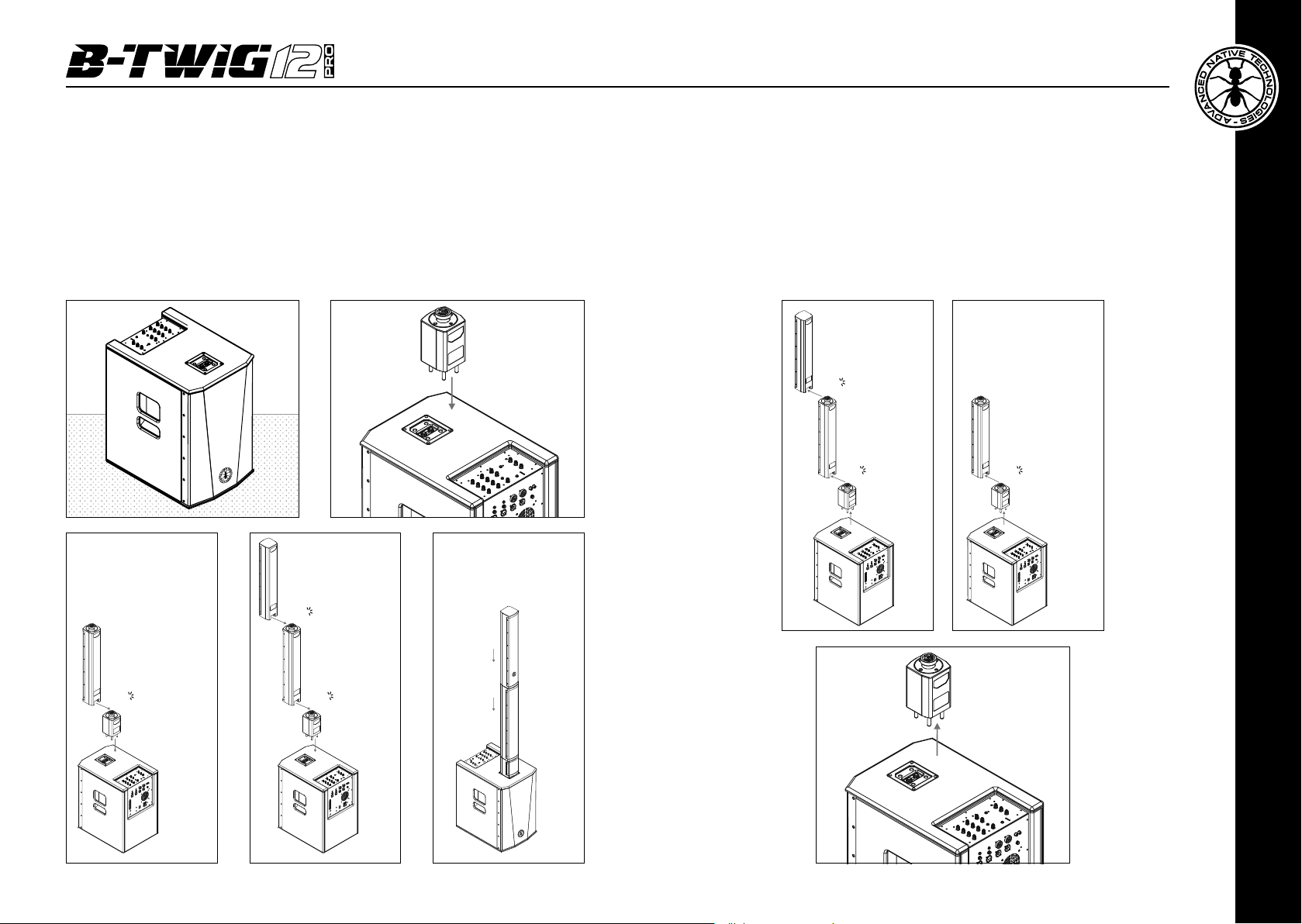
ASSEMBLY:
DISASSEMBLY:
• Place the subwoofer on a level surface with no drops. (Fig. 1)
• Fasten the support element to the subwoofer by inserting the four steel guiding pins and
the two audio jacks into their respective sockets. (Fig. 2)
• Slide the lower part of the rst column speaker (A) into the upper part of the support until
it locks. (Fig. 3)
• Repeat the operation to x the second column speaker (B) with the upper part of the rst
column speaker (A). (Fig. 4 - Fig. 5)
Fig 1 Fig 2
Fig 3
Lock A,
following arrow
direction
B
Click
Lock B,
following arrow
direction
Fig 4
Insert the support
element, following
arrow direction
Fig 5
• Press the upper column speaker (B) from the back to release it from the lower
column speaker (A). (Fig. 6)
• Repeat the same operation between the lower column (A) and the support
element. (Fig. 7)
• Remove the support from the subwoofer and store all the elements. (Fig. 8)
Fig 6
Unlock B,
following arrow
B
Click
direction
A A
Click Click
following arrow
Fig 7
Unlock A,
direction
A
Click
User manual | B-TWIG 12 PRO
16
A
Click
B
Fig 8
Pull the support,
following arrow
direction
A
ENGLISH
17
17
B-TWIG 12 PRO | User manual
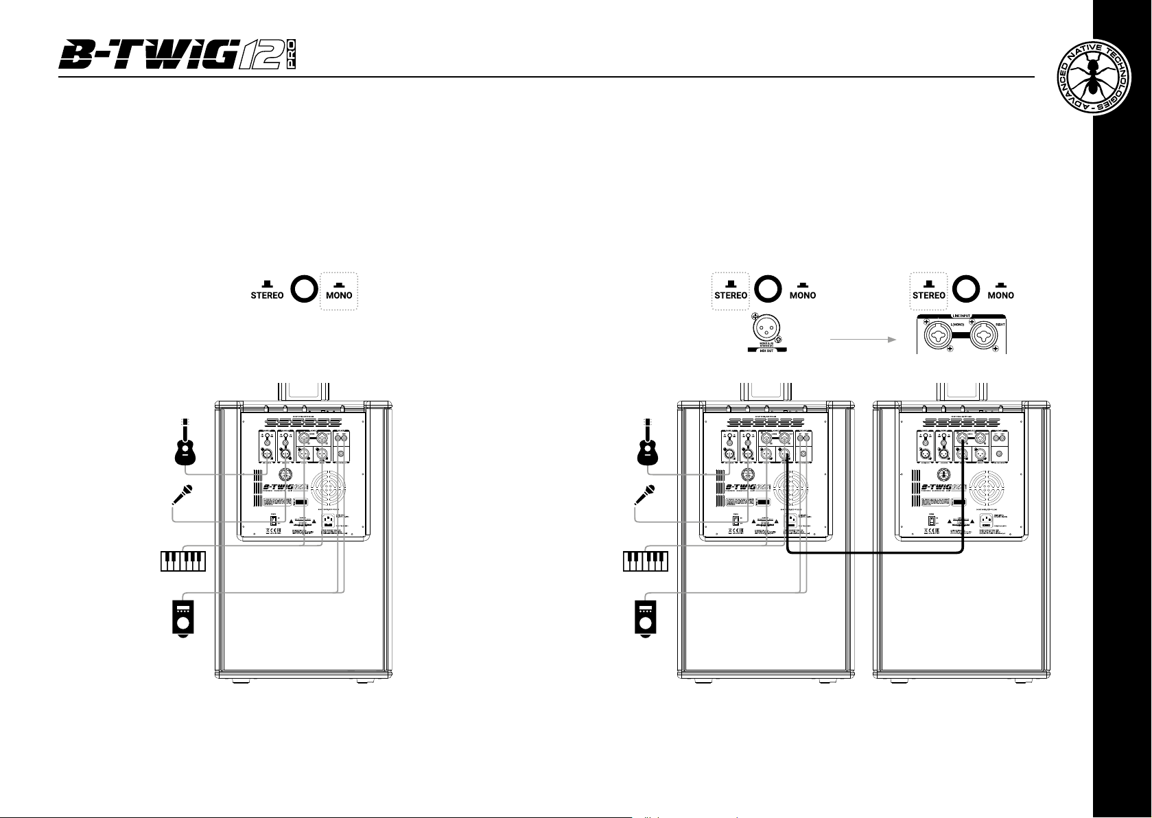
5 | APPLICATION CONFIGURATIONS
MONO - 1x B-TWIG 12 PRO
Use this MONO conguration as sound system for a small venue with one B-TWIG12 PRO
system.
All the signals present on the input channels, CH1 - CH2 - CH3 - AUX / BT, are internally
summed and reproduced in MONO.
STEREO - 2x B-TWIG 12 PRO
Use this STEREO conguration to create a medium venue sound system, using
two B-TWIG12 PRO systems. The signal present in the left channel (L) of all
stereo inputs is summed and exclusively played back by the main system, while
the signal in the right channel (R) of all stereo inputs is summed and exclusively
played back from the additional system.
Adjust the MAIN LEVEL of each system in the same way.
NOTE
: The signal of the Mono inputs CH1 and CH2 is reproduced equally on the
left (main system) and on the right (additional system)
Main System (L) Additional System (R)
APPLICATIONS
• Live Solo / Duo
• Piano Bar / Dj Set
• A/V Multi media, small dancing venues
• Cabaret / Corporate meetings
User manual | B-TWIG 12 PRO
18
APPLICATIONS
• Live band / Rehearsal rooms
• Piano Bar / Dj Set
• A/V Multi media, dancing venues
• Fixed installations / Theatre
B-TWIG 12 PRO | User manual
ENGLISH
19
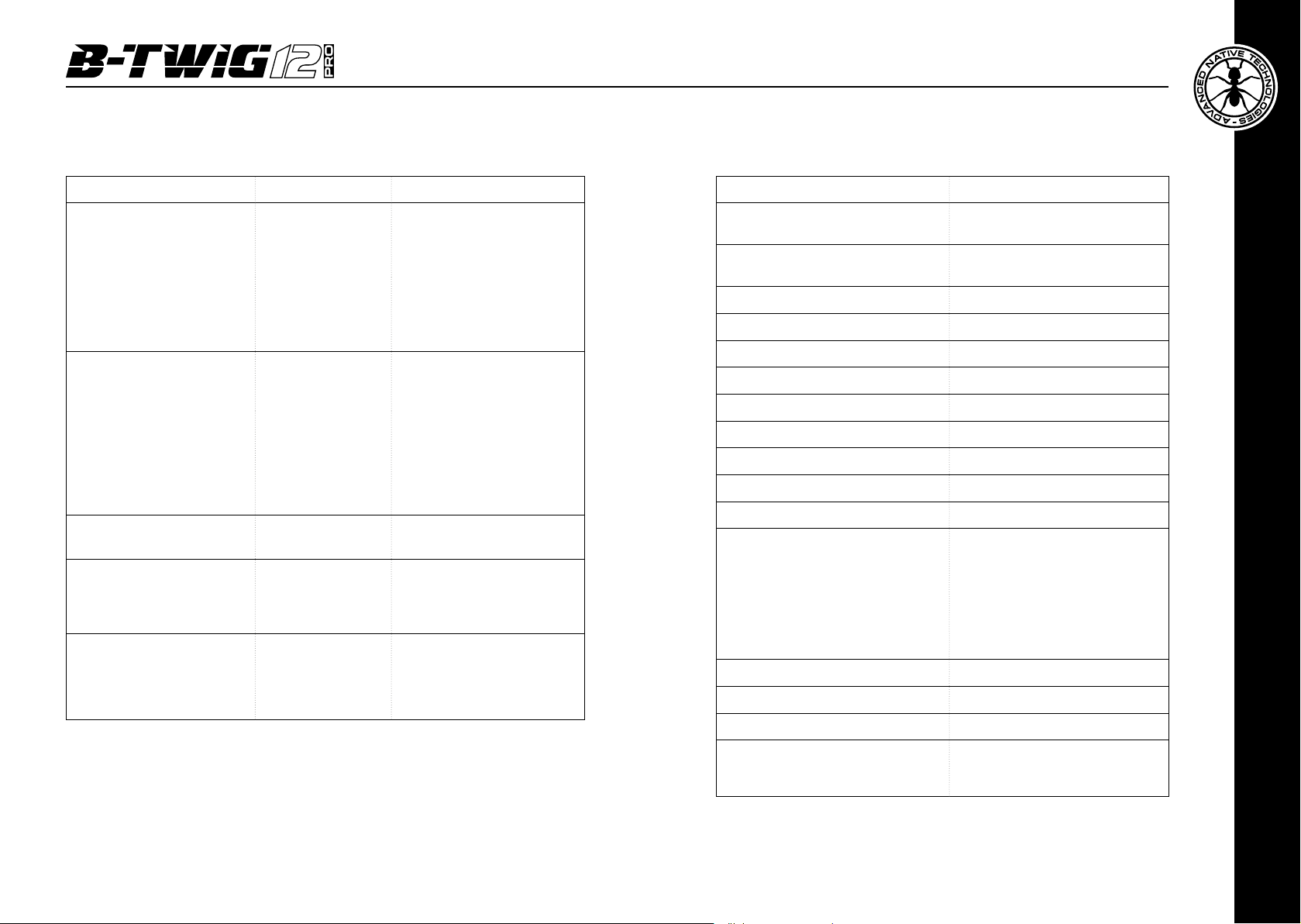
7 | TECHNICAL SPECIFICATIONS6 | TROUBLESHOOTING
PROBLEM LED SOLUTION
Power LED
turned off.
No sound or very low
sound level
Distortion
Booming sound Lower SUB level
Harsh sound
Attenuation of some
frequencies that are
predominant, not very
faithful signal, reverberating
environment
Power LED
turned on, but low
MAIN LEVEL.
SIG/CLIP LED lit red Lower inputs and/or
ON/LIMIT LED
lit green
Make sure the system is
properly connected to the
mains outlet.
Raise MAIN LEVEL knob.
MAIN LEVEL knob.
Check the source level
Check proper connection
between subwoofer and A/B
speaker elements
Raise SUB level
Lower MAIN LEVEL knob.
Try choosing a different
preset, minding also the
acoustic characteristics of the
environment.
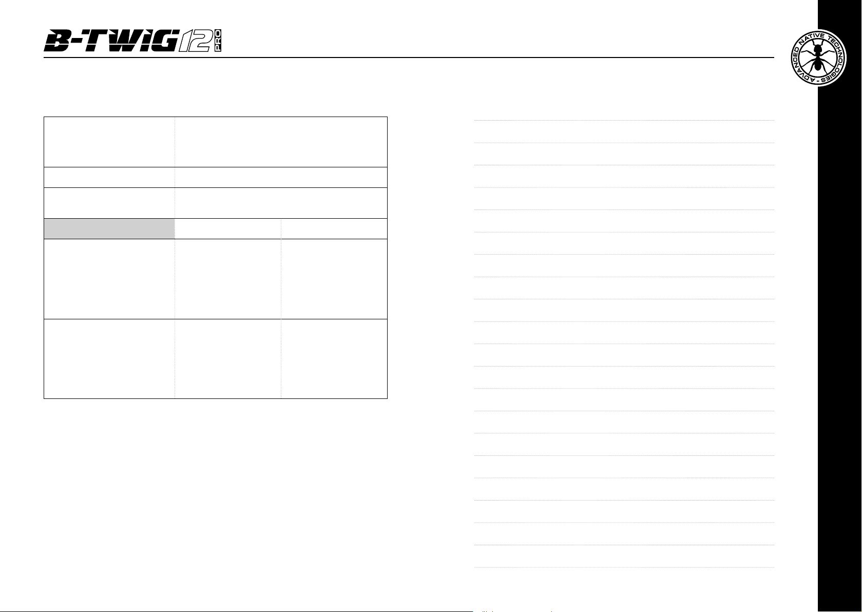
System type Active column system
Subwoofer (B-TWIG 12S PRO)
Column speaker (B-TWIG 12CS PRO)
Average dispersion 120°
Frequency response 45Hz - 20kHz
MAX SPL 126 dB
Amplication Class D
Peak power (LF + HF) 2800 W
Crossover 24dB/Oct @ 200Hz
DSP 56Bit
AD/DA conversion 24Bit / 48kHz
System EQ 4 presets
I/O connectors
Power supply 220-240V~ 50-60Hz
Fuse T4A L 250V~
Power consumption 700 W
Vented enclosure
1 x 12” Ferrite - 2.5” VC - custom speaker
12 x 3.5” - 1” VC - neodymium custom
speakers
CH1 & CH2: 2 x XLR-F + 2 x 6,35mm
(1/4”) jack
CH 3 LINE IN: 2 x combo L/R
TAPE IN: RCA L/R
AUX IN: 1 x 3.5mm mini-jack
SUB OUT/MIX OUT: 2 x XLR-M
DFX FOOTWSWITCH: 1 x 6,35mm (1/4”)
jack
User manual | B-TWIG 12 PRO
20
Fastening mechanism
Connector with automatic coupling and
circular connection
Speaker rotation - 90 degrees left/right
B-TWIG 12 PRO | User manual
ENGLISH
21
Cabinets material:
- Subwoofer
8 | NOTES
15mm plywood
- Column speakers / Support element
Cabinet treatment Scratch-resistant coating with high mechanical resistance
Optional accessories
Dimensions (W x H x D)
Weight
High density MDF
Transport cover for subwoofer and column speakers kit
Subwoofer skate or transport wheels
B-TWIG 12S PRO B-TWIG 12CS PRO
Subwoofer:
370 x 583 x 500mm.
14.6” x 23” x 19.7” (approx)
Support element:
105 x 230 x 107mm.
4.1” x 9” x 4.2” (approx)
Subwoofer:
20,2Kg
44.5 lbs. (approx)
Support element:
300g
0.6 lbs. (approx)
Upper speaker A:
105 x 680 x 107mm.
4.1” x 26.7” x 4.2” (approx)
Lower speaker B:
105 x 680 x 107mm.
4.1” x 26.7” x 4.2” (approx)
Upper speaker A:
5,1Kg
11.3 lbs. (approx)
Lower speaker B:
5,2Kg
11.5 lbs. (approx)
User manual | B-TWIG 12 PRO
22
B-TWIG 12 PRO | User manual
ENGLISH
23

INDICE
1 | Introduzione 25
2 | Installazione 26
1 | INTRODUZIONE
Grazie per aver acquistato un prodotto A.N.T - Advanced Native Technologies!
Nel sistema array B-TWIG 12 PRO abbiamo profuso la nostra passione ed il
nostro know-how maturato nel corso degli anni per offrirvi un prodotto che
soddis le vostre esigenze e mantenga la sua qualità nel tempo.
3 | Descrizione 27
3.1 | Ingressi & controlli 27
3.2 | Connessioni 31
3.3 | Alimentazione 35
3.4 | KIT B-TWIG 12CS PRO 36
4 | Istruzioni di montaggio e smontaggio del sistema 37
5 | Congurazioni di utilizzo 40
6 | Soluzione dei problemi 42
7 | Caratteristiche tecniche 43
8 | Note 45
CONTENUTO DELL’IMBALLO
• 1x Subwoofer attivo B-TWIG 12S PRO comprendente:
n.1 Elemento di sostegno
n.1 cavo di alimentazione (VDE)
• 1x Kit B-TWIG 12CS PRO comprendente:
n.2 diffusori passivi a colonna
• 1x Manuale d’uso - Sezione 1
• 1x Manuale d’uso - Sezione 2
Progettato appositamente per un utilizzo estremamente immediato e
semplice, risponde alle esigenze di quanti desiderano un sistema audio
in grado di fornire ottime prestazioni, versatilità di connessioni e il miglior
rapporto qualità/prezzo possibile nella sua categoria.
Caratterizzato da un look elegante e contemporaneo, coniuga in maniera
ottimale caratteristiche professionali di grande qualità ed eccezionale valore
come:
• DSP interno con 4 preset di equalizzazione;
• Unità DFX integrata caratterizzata da 16 preset con mandate e ritorno
effetti inclusi;
• Mixer da 4CH provvisto di molteplici combinazioni I/O e connessione
Bluetooth®;
• Soluzioni acustiche ottimizzate per garantire ottima qualità sonora in
un'ampia gamma di frequenze;
• Meccanismo esclusivo di rotazione e orientamento delle colonne di 90°
che può essere opportunatamente utilizzato per direzionare la copertura
acustica in base alle esigenze di utilizzo, installazione e posizionamento
del sistema.
Sono disponibili diversi accessori opzionali per un utilizzo più semplice ed
immediato del prodotto.
Ritagliatevi qualche minuto per leggere questo manuale di istruzioni in modo
tale da ottenere rapidamente il massimo delle performance da questo prodotto.
Per le istruzioni relative a sicurezza, le precauzioni, la garanzia e lo smaltimento
fate riferimento all'allegato sezione 2.
Le avvertenze nel presente manuale devono essere osservate
congiuntamente al “MANUALE D’USO - SEZIONE 2”.
Manuale d’uso | B-TWIG 12 PRO
24
Per ulteriori informazioni su tutti i prodotti del catalogo A.N.T consultate il
nostro sito: www.ant-intomusic.com
ITALIANO
B-TWIG 12 PRO | Manuale d’uso
25
2 | INSTALLAZIONE
Il sistema è composto da un subwoofer attivo
B-TWIG 12S PRO e dal kit B-TWIG 12CS PRO:
A | Maniglie laterali incassate.
B | Connettore di attacco e sgancio rapido degli elementi.
C | Elemento di sostegno/stativo.
D | Diffusori a colonna passivi dotati di maniglie posteriori incassate.
E | Piedini antiscivolamento in gomma.
F | Predisposizione di ssaggio per ruote di trasporto.
B-TWIG 12S PRO B-TWIG 12CS PRO
DA B
B
E
3 | DESCRIZIONE
2
3
1 5
6
7
8
9
A
Manuale d’uso | B-TWIG 12 PRO
26
E CF
B
D
4
3.1 | INGRESSI & CONTROLLI
B
1 CH1 / CH2 - INDICATORE BICOLORE SIG/CLIP
Verde: il segnale è presente nel rispettivo canale.
Rosso: il segnale in ingresso è molto forte ed è prossimo alla distorsione.
Se l’indicatore si accende con continuità, è necessario ridurre il segnale in
ingresso o regolare diversamente l’EQ del canale riducendo l’esaltazione
introdotta dai guadagni dei toni HIGH-LOW.
2 CH1 / CH2 - DFX LEVEL
Questa mandata, influenzata dal controllo di livello del singolo canale, permette
di regolare il segnale inviato all’unità effetti interna DFX.
B-TWIG 12 PRO | Manuale d’uso
ITALIANO
27
3 CH1 / CH2 - EQUALIZER
Questo equalizzatore a due bande permette di enfatizzare o attenuare le frequenze alte
e/o basse per ottenere il suono desiderato.
4 CH1 / CH2 / LINE/TAPE IN - LEVEL
Queste manopole regolano il volume del canale corrispondente, ruotatele verso destra
per alzare il livello, verso sinistra per diminuirlo.
5 MAIN SECTION - INDICATORE BICOLORE SIG/CLIP
Verde: il segnale è presente nel canale MAIN.
Rosso: il segnale in ingresso al MAIN è molto forte ed è prossimo alla distorsione.
Se l’indicatore si accende con continuità, è necessario ridurre il livello MAIN LEVEL o
regolare diversamente i livelli di CH1 / CH2 / LINE/TAPE IN e AUX.
6 INDICATORE ON
Il led ON si accende quando l’apparecchio è collegato alla rete elettrica e l'interruttore
di accensione è posizionato su ON.
7 MAIN LEVEL
Questo controllo regola il volume di uscita generale del sistema. Girate la manopola in
senso orario per aumentare il volume o in senso antiorario per abbassarlo.
8 SUB LEVEL
Questo controllo regola il volume di uscita del subwoofer e permette di bilanciare il livello
delle frequenze basse, in base alla risposta acustica dell’ambiente. Girate la manopola
in senso orario per aumentare il volume del sub o in senso antiorario per abbassarlo.
9 TASTO STEREO / MONO
Permette di selezionare la congurazione di ascolto del sistema nelle due modalità di
funzionamento: STEREO o MONO.
- Posizionate il tasto su MONO quando utilizzate un singolo sistema B-TWIG 12 PRO;
in questo caso tutti i segnali stereo presenti in ingresso sono sommati internamente.
È possibile collegare una unità supplementare tramite l’uscita MIX OUT MONO (L/R)
duplicando il fronte sonoro.
- Posizionate il tasto su STEREO quando utilizzate due sistemi B-TWIG 12 PRO; in
questo caso tutti i segnali stereo presenti in ingresso sono miscelati in LEFT/RIGHT e
contemporaneamente associati ai rispettivi sistemi come segue:
il canale sinistro (L) di tutti gli ingressi stereo è riprodotto dall’unità principale, mentre
il canale destro (R) di tutti gli ingressi stereo è riprodotto dall’unità supplementare,
collegata all’uscita MIX OUT STEREO (R)
10 PAIR - TASTO & INDICATORE LUMINOSO
Utilizzate questo tasto per sincronizzare il dispositivo Bluetooth® con il sistema usando
la seguente procedura:
• premete il tasto PAIR per circa 3 secondi nché il led lampeggia ritmicamente;
• per inizializzare la sincronizzazione attivate il Bluetooth® dall’interfaccia utente del vostro
dispositivo mobile;
• nell'elenco degli apparecchi rilevati dal vostro smartphone o tablet selezionate
“B-TWIG 12 PRO” per sincronizzare il vostro dispositivo mobile con il sistema.
Al termine dell'operazione la spia rimane accesa in maniera ssa e la
riproduzione dei brani può essere avviata, a condizione che la distanza
massima tra il dispositivo non superi i 10 metri.
La connessione Bluetooth
®
può essere disattivata in qualsiasi momento
mantenendo premuto per 3 secondi il tasto PAIR o dissociando l’unità
B-TWIG 12 PRO dal dispositivo mobile. In entrambi i casi l’indicatore luminoso
lampeggia lentamente ogni 5 secondi, comunicando la disattivazione del
collegamento.
11 AUX IN STEREO
Questo ingresso stereo da 3,5mm accetta il segnale via cavo da dispositivi
esterni, come smartphone, tablet, PC o qualsiasi altro apparecchio dotato
di uscita mini-jack stereo.
11
12
10
13
14
15
ITALIANO
Manuale d’uso | B-TWIG 12 PRO
28
B-TWIG 12 PRO | Manuale d’uso
29

12 BLUETOOTH® / AUX - LEVEL
Questa manopola regola il volume degli ingressi AUX IN STEREO e BLUETOOTH®,
ruotatela verso destra per alzare il livello, verso sinistra per diminuirlo.
13 DFX PRESETS
Questo selettore a 16 posizioni vi permette di scegliere il tipo di effetto.
Per un riferimento rapido l'elenco degli effetti è riportato di anco a sinistra del selettore.
I primi 4 effetti emulano diversi riverberi caratterizzati da riflessioni del suono all’interno
di due ambienti diversi, i 4 successivi (5-8) sono suggeriti in particolare per la voce o
percussioni in genere, i delay stereo generano il classico effetto di ritardo del segnale
principale, inne sono presenti le combinazioni multi-effetto (11-16) ideali per la voce
e una buona parte di strumenti solisti.
14 DFX TO MAIN
Questa manopola stabilisce il livello complessivo del segnale dell'unità effetti DFX per
l'uscita principale.
Utilizzatela per aumentare o diminuire la quantità dei segnali processati da inviare al
MAIN LEVEL.
15 DSP - TASTO PRESET E INDICATORE LUMINOSO
Premete questo tasto per selezionare l’equalizzazione adeguata all’utilizzo del sistema.
La spia illuminata indica il preset attivato.
• DJ SOUND
Indicato per le installazioni in disco club o un DJ SET mobile, per i quali è richiesta una
timbrica d’impatto con una predominanza di bassi molto profondi e coinvolgenti.
• PLAYBACK
Per l’ascolto e utilizzo di musica riprodotta (lettori CD, MP3, etc.). Le frequenze basse
e alte sono enfatizzate.
Indicato per tutte quelle situazioni nelle quali la musica è diffusa come sottofondo
anche a volumi contenuti.
• FF OPENED
Questo preset ottimizza l’intelligibilità del parlato con una risposta dinamica accurata
e bilanciata.
È particolarmente adatto per la diffusione di annunci, avvisi e messaggi vocali, cosi
come per l’ascolto e utilizzo di musica riprodotta, con entrambe le colonne direzionate
in maniera opposta rispetto al fronte d’onda principale di ascolto.
NOTA
: il preset FF OPENED non sostituisce una corretta disposizione dei diffusori, né
interviene con ritardi differenziati di emissione del segnale su ogni singolo trasduttore.
• LIVE SOUND
Per l’utilizzo del sistema durante le performance dal vivo. Caratterizzato da una risposta
lineare e fedele, è indicato per concerti in locali, musicisti e cantanti.
3.2 | CONNESSIONI
1
2
3
1 TASTO HI-Z / MIC - CH1
Questo tasto permette di commutare l’impedenza del segnale di ingresso
nel canale 1.
Posizionate il tasto su MIC per collegare un microfono e su HI-Z quando
avete la necessità di collegare una chitarra elettroacustica. Il tasto agisce
solo sulla presa di ingresso Jack da 6,35mm.
2 HI-Z INPUT - CH1
Ingresso bilanciato con presa jack da 6,35mm. È possibile usare anche un
cavo non bilanciato.
3 MIC INPUT - CH1
Ingresso microfono bilanciato con presa XLR-F.
4 TASTO LINE / MIC - CH2
Posizionate il tasto su LINE per l’utilizzo di una sorgente a livello linea o su
MIC per l’utilizzo di un microfono.
5 LINE INPUT - CH2
Ingresso bilanciato con presa jack da 6,35 mm. È possibile usare anche un
cavo non bilanciato.
6 MIC INPUT - CH2
Ingresso microfono bilanciato con presa XLR-F.
4
5
6
ITALIANO
Manuale d’uso | B-TWIG 12 PRO
30
B-TWIG 12 PRO | Manuale d’uso
31

ATTENZIONE
: quando collegate due sistemi in congurazione stereo,
impostate i controlli del sistema supplementare (R) in modo identico per
7
ottenere un fronte sonoro stereo equilibrato e bilanciato.
11 DFX FOOTSWITCH
8
Collegate a questa presa jack sbilanciata un pedale esterno per l’inserimento
o l’esclusione degli effetti interni. Premete una volta per disattivare gli effetti
e una seconda volta per riattivarli.
10
12 SISTEMA DI CONNESSIONE RAPIDO DEGLI ELEMENTI
Questo meccanismo permette l’aggancio e lo sgancio degli elementi che
compongono il sistema, assicurandone la perfetta funzionalità in tutta
sicurezza.
7 LINE INPUT L/R
Ingressi linea bilanciati con prese COMBO (XLR-F + Jack da 6,35mm); collegando un
solo cavo alla presa L (MONO), il segnale è processato internamente come mono. Il
volume di questi ingressi è regolato tramite la manopola del canale 3.
8 TAPE INPUT L/R
Ingresso linea sbilanciato con prese RCA L/R. Collegate a queste prese l'uscita di un
apparecchio hi- (CD) o altro dispositivo con uscite RCA L/R. Il volume di questi ingressi
è regolato tramite la manopola del canale 3.
9 SUB OUT
Uscita XLR-M bilanciata per il rilancio del segnale verso un altro subwoofer attivo. Il
livello è influenzato dalla manopola SUB LEVEL e dalla manopola MAIN.
10 MIX OUT L/R - R
Uscita XLR-M bilanciata per il rilancio del segnale MAIN MIX ad un altro sistema B-TWIG
12 PRO.
L’uscita è influenzata dalla posizione del tasto STEREO/MONO descritto al punto 9, cap. 3.1.
Con il tasto abbassato (MONO): tutti i segnali presenti sui canali di ingresso sono sommati
internamente e l'uscita MIX OUT fornisce il segnale per un sistema supplementare di
rinforzo.
Con il tasto sollevato (STEREO): il segnale presente nel canale sinistro (L) di tutti gli
ingressi stereo viene associato e riprodotto esclusivamente dal sistema principale,
mentre il segnale presente nel canale destro (R) di tutti gli ingressi stereo viene associato
e riprodotto dal sistema supplementare.
NOTA
: Il segnale degli ingressi Mono CH1 e CH2 è riprodotto in modo uguale a sinistra
(sistema principale) e a destra (sistema supplementare)
119
+-
-+
Contatti audio (+ / -)
Raccordo circolare di
aggancio e rotazione
(maschio)
+
-
Perni di guida
in acciaio
Raccordo circolare
di aggancio e rotazione
(femmina)
ITALIANO
Manuale d’uso | B-TWIG 12 PRO
32
B-TWIG 12 PRO | Manuale d’uso
33

13 MANIGLIE LATERALI INCASSATE
SUBWOOFER
Utilizzate queste maniglie per il trasporto ed
il posizionamento del subwoofer. Non usatele
per appendere il subwoofer o per bloccarlo in
qualsiasi posizione.
13
14 MANIGLIE POSTERIORI INCASSATE
COLONNE / ELEMENTO DI SOSTEGNO
Utilizzate queste maniglie per il trasporto ed
il posizionamento degli elementi. Non usatele
per appendere i diffusori alla parete, al softto o
per bloccare le colonne in qualsiasi posizione.
3.3 | ALIMENTAZIONE
1
3
2
1 MAINS INPUT
Presa IEC di ingresso con ltro di rete integrato. Ogni confezione è fornita
del cavo di alimentazione necessario, specico per la vostra zona. Inserite
in questa presa il cavo per l'alimentazione elettrica ma accertatevi che
l’apparecchio sia spento prima di collegare il cavo alla rete. Per la vostra
sicurezza, non scollegate mai il polo centrale di terra.
ATTENZIONE!
Non rimuovere mai la griglia frontale di protezione del prodotto. Per
prevenire il pericolo di scossa elettrica, in caso di danneggiamento
accidentale o sostituzione della griglia di protezione (da effettuarsi presso
il servizio assistenza), disconnettere immediatamente l’alimentazione.
Manuale d’uso | B-TWIG 12 PRO
34
14
ATTENZIONE: Per ridurre il rischio di scosse elettriche, non connettere
mai l’alimentazione di rete all’apparecchio mentre la griglia è rimossa.
2 FUSE
Fusibile di protezione integrato alla presa elettrica.
ATTENZIONE: Sostituite il fusibile unicamente con uno dello stesso
tipo e con gli stessi valori. Se il fusibile continua a saltare rivolgetevi
ad un centro di assistenza autorizzato.
3 POWER ON/OFF
Interruttore per accensione/spegnimento dell'apparecchio.
B-TWIG 12 PRO | Manuale d’uso
ITALIANO
35
 Loading...