

Angelantoni Industrie RL, FRL Service manual
ARMADI FRIGORIFERI
REACH-IN REFRIGERATORS
SERIE RL - FRL
RL - FRL SERIES
iso 9001:2000
513427-F04
513427-F01
513427-F05
513427-F02
Manuale di installazione, uso e manutenzione
Installation, use and maintenance handbook
513427-F06
nato aqap110
iso 14001
513427-F03
Angelantoni Industrie S.p.A.
06056 Massa Martana (Pg) Italy
Tel. (++39) 075
Fax (++39) 075
Internet: www.angelantoni.it
E-Mail:info@angelantoni.it
.
8955.1 (a.r.)
.
8955200
Cod. 513417 - Rel. 200505

464 Località Cimacolle
06056 Massa Martana (Pg) Italy
AVVERTENZA IMPORTANTE
I prodotti realizzati dal costruttore sono caratterizzati da un elevato contenuto tecnologico che talvolta richiede
un adattamento tecnico di parti o componenti altrimenti reperibili sul mercato nella loro versione standard
commerciale. Pertanto, la sostituzione di parti o componenti con altri non originali, ossia non forniti e garantiti
direttamente dal COSTRUTTORE, nonché l’accertamento di interventi tecnici effettuati da personale non autorizzato,
comporteranno l’immediata cessazione della garanzia, se in essere, e comunque di qualsiasi responsabilità nei
confronti dell’acquirente e di terzi, da parte del COSTRUTTORE stesso.
IMPORTANT WARNING
The high level of technology of the products made by the manufacturer occasionally requires components to be
adapted from parts normally found on the market in their standard commercial version. Therefore, if it should be
ascertained that any parts have been replaced with other components that are not original, i.e. that have not
been supplied and guaranteed directly by the MANUFACTURER, or that any unauthorised technical interventions
have been carried out, the guarantee, if any is in force, shall be considered no longer valid and the MANUFACTURER
himself shall no longer be held responsible towards the purchaser and towards third parties.
AVVERTISSEMENT IMPORTANT
Les produits réalisés par le constructeur sont caractérisés par un haut niveau technologique qui demande par fois
une adaptation technique de parties ou de composants autrement disponibles sur le marché dans leur version
commerciale standard. Pour cette raison, la substitution de parties ou composants par d’autres non originaux,
c’est à dire non fournis et garantis directement par le CONSTRUCTEUR, ou bien la constatation que du personnel
non autorisé a effectué des interventions techniques; auront pour conséquence l’immédiate cessation de la garantie
en cours et de toute façon de toutes responsabilités du CONSTRUCTEUR vis à vis de l’acheteur ou de tierces
parties.
WICHTIGE WARNUNG
Das hohe technische Niveau der Produkte des Herstellers erfordert teilweise Komponenten, die verändert
werden müssen gegenüber handelsüblichen Produkten ; wie sie am Markt zu finden sind.
Beim Austausch von Teilen oder Komponenten; die nicht dem Orginal entsprechen, das heißt nicht direkt vom
HERSTELLER geliefert und garantiert wurden, bzw. daß technische Veränderungen durch nicht autorisiertes
Personal vorgenommen wurde, gilt die Garantie, falls noch in Kraft, als erloschen und der HERSTELLER kann
nicht mehr länger haftbar gemacht werden gegenüber dem Käufer und Dritten.
AVISO IMPORTANTE
Los productos elaborados por el fabricante se caracterizan por un alto nivel tecnológico y ocasionalmente
requieren adaptaciones técnicas de partes o componentes que normalmente se encuentran en el mercado en
su versión comercial estándar.
Por tanto, la sustitución de partes o componentes, por otros que no sean originales, es decir no suministrados
y garantizados por el FABRICANTE, o bien se constata la intervención técnica por de personal no autorizado,
supondrá el cese inmediato de la garantía, si está en vigor, así como de cualquier otra responsabilidad del
FABRICANTE de cara tanto al comprador como a terceras personas.

SOMMARIO
1 RIEPILOGO DEI DATI DI MARCATURA.............................................. 2
2AVVERTENZE ..................................................................................... 3
2.1 AVVERTENZE GENERALI........................................................... 3
2.2 AVVERTENZE PER IL TRASPORTO E LA MOVIMENTAZIONE. 4
2.3 AVVERTENZE PER L'INSTALLAZIONE ...................................... 4
2.4 AVVERTENZE PER IL PERSONALE ADDETTO......................... 4
2.5 AVVERTENZE PER LA MANUTENZIONE .................................. 5
2.6 SPIEGAZIONE DEI SIMBOLI....................................................... 5
3 CARA TTERISTICHE TECNICHE......................................................... 6
3.1 DATI TECNICI............................................................................... 6
3.2 FUSIBILI ..................................................................................... 10
3.3 CONDIZIONI AMBIENTALI......................................................... 10
4MOVIMENTAZIONE E DISIMBALLO ................................................. 11
4.1 REQUISITI DEL PERSONALE................................................... 11
4.2 STATO DELLA MACCHINA ........................................................ 11
4.3 MEZZI NECESSARI PER LA MOVIMENTAZIONE .................... 11
4.4 DISIMBALLO .............................................................................. 12
4.5 IMMOBILIZZAZIONE DELLA MACCHINA ................................. 13
5 DESCRIZIONE DEL SISTEMA.......................................................... 14
5.1 VISTA GENERALE ..................................................................... 14
5.2 VISTA POSTERIORE ................................................................. 15
5.3 VISTA INTERNA ......................................................................... 16
5.4 SISTEMA DI CONTROLLO ........................................................ 17
5.5 SISTEMA REFRIGERANTE....................................................... 18
5.6 FUNZIONAMENTO DEL CIRCUITO DI RAFFREDDAMENTO.. 18
5.7 STRUTTURA .............................................................................. 18
5.8 FUNZIONAMENTO DEL CIRCUITO ELETTRICO ..................... 18
6 INSTALLAZIONE ............................................................................... 19
6.1 POSA DELLA MACCHINA ......................................................... 19
6.1.1Montaggio maniglia ............................................................ 19
6.2 COLLEGAMENTO ELETTRICO................................................. 20
6.2.1Collegamento elettrico alla rete ......................................... 20
6.2.2Sostituzione del cavo di alimentazione (senza pannello
aggiuntivo).......................................................................... 20
6.2.3 Sostituzione del cavo di alimentazione (con pannello aggiuntivo) 21
6.2.4 Collegamento allarme remoto (se presente pannello aggiuntivo) 21
7 USO PREVISTO DAL FABBRICANTE .............................................. 22
7.1 SCOPO DELLE MACCHINE ...................................................... 22
7.2 DESTINAZIONE DELLE MACCHINE......................................... 22
7.3 OPERATORE.............................................................................. 22
7.4 LIMITAZIONI D’USO................................................................... 22
7.5 RISCHI RESIDUI ........................................................................ 22
8AVVIAMENTO.................................................................................... 23
8.1 AVVIAMENTO ............................................................................ 23
8.2 IMPOSTARE LA TEMPERATURA .............................................. 23
8.3 DESCRIZIONE DEL PANNELLO COMANDI AGGIUNTIVO...... 23
8.3.1Sistema di allarme ............................................................. 24
8.3.2 Regolazione della temperatura di soglia del sistema di allarme.25
8.3.3Arresto ............................................................................... 25
8.4 ALCUNE PRECAUZIONI............................................................ 25
9 USO ........................................................................................... 26
9.1 INDICAZIONI PER IL RAFFREDDAMENTO .............................. 26
9.2 REGISTRATORE GRAFICO DI TEMPERATURA ...................... 26
9.2.1Uso del registratore............................................................ 27
10 ORGANI DI SICUREZZA-VERIFICA E TARATURA ......................... 29
11 MANUTENZIONE ............................................................................. 29
11.1CONTROLLO DEL SISTEMA DI ALLARME (Opzionale)........... 29
11.2SBRINAMENTO ......................................................................... 29
11.3PULIZIA DELLA STRUTTURA ................................................... 30
11.3.1 Pulizia delle guarnizioni ................................................... 30
11.3.2 Pulizia del condensatore ................................................. 30
11.4MANUTENZIONE DEL SISTEMA DI RAFFREDDAMENTO...... 30
11.5MANUTENZIONE PARTE ELETTRICA- ELETTRONICA .......... 30
11.6SOSTITUZIONE BATTERIA INDICATORE DI TEMPERATURA 30
12 INCONVENIENTI E RIMEDI . 33
13 DISINSTALLAZIONE ........................................................................ 32
13.1MESSA FUORI SERVIZIO ......................................................... 32
13.2ROTTAMAZIONE........................................................................ 32
14 SCHEMI ........................................................................................... 33
14.1SCHEMA FRIGORIFERO .......................................................... 33
14.2SCHEMA ELETTRICO (senza pannello aggiuntivo) ................. 34
14.3SCHEMA ELETTRICO (con pannello aggiuntivo) ...................... 35
SUMMARY
1 SUMMARY OF RATING PLATE DATA ................................................. 2
2WARNINGS ......................................................................................... 3
2.1 GENERAL WARNINGS ................................................................ 3
2.2 WARNINGS FOR TRANSPORT AND HANDLING ...................... 4
2.3 WARNINGS FOR INSTALLATION................................................ 4
2.4 WARNINGS FOR PERSONNEL IN CHARGE OF THE MACHINE4
2.5 WARNINGS FOR MAINTENANCE .............................................. 5
2.6 EXPLANATION OF SYMBOLS..................................................... 5
3 TECHNICAL SPECIFICATIONS .......................................................... 6
3.1 TECHNICAL DATA........................................................................ 6
3.2 FUSES........................................................................................ 10
3.3 ENVIRONMENTAL CONDITIONS.............................................. 10
4 HANDLING AND REMOVAL OF PACKAGING.................................. 11
4.1 PERSONNEL REQUISITES....................................................... 11
4.2 MACHINE CONDITIONS............................................................ 11
4.3 EQUIPMENT NEEDED FOR HANDLING .................................. 11
4.4 REMOVAL OF PACKAGING....................................................... 12
4.5 HOW TO BLOCK THE MACHINE............................................... 13
5 DESCRIPTION OF THE SYSTEM..................................................... 14
5.1 GENERAL VEW ......................................................................... 14
5.2 REAR VIEW................................................................................ 15
5.3 INTERNAL VIEW ........................................................................ 16
5.4 CONTROL SYSTEM .................................................................. 17
5.5 COOLING SYSTEM ................................................................... 18
5.6 FUNCTIONING OF THE COOLING SYSTEM ........................... 18
5.7 STRUCTURE INSULATION ....................................................... 18
5.8 FUNCTIONING OF THE ELECTRIC SYSTEM .......................... 18
6INSTALLATION .................................................................................. 19
6.1 POSITIONING OF THE MACHINE............................................. 19
6.1.1Handle assembly................................................................ 19
6.2 ELECTRICAL WIRING ............................................................... 20
6.2.1How to connect to the electrical mains supply ................... 20
6.2.2Replacement of the supply cable (without additional panel)20
6.2.3Replacement of the supply cable (with additional panel) ... 21
6.2.4Remote alarm (only with additional panel) ......................... 21
7 USE FORESEEN BY THE MANUFACTURER .................................. 22
7.1 AIM OF THE MACHINES ........................................................... 22
7.2 INTENDED USE OF THE MACHINES ....................................... 22
7.3 OPERATOR ................................................................................ 22
7.4 USE LIMITS................................................................................ 22
7.5 USE OF PROTECTIVE CLOTHING ........................................... 22
8START -UP .......................................................................................... 23
8.1 SWITCHING ON......................................................................... 23
8.2 SETTING THE TEMPERA TURE................................................. 23
8.3 DESCRIPTION OF ADDITIONAL PANEL .................................. 23
8.3.1Alarm system ..................................................................... 24
8.3.2Adjustment of alarm system temperature threshold .......... 25
8.3.3Tutning off .......................................................................... 25
8.4 SOME PRECAUTIONS .............................................................. 25
9 USE ........................................................................................... 26
9.1 INSTRUCTIONS FOR COOLING............................................... 26
9.2 TEMPERATURE CHART RECORDER ...................................... 26
9.2.1Use of the recorder ............................................................ 27
10 SAFETY DEVICES- CHECK AND SET-UP ...................................... 29
11 MAINTENANCE ................................................................................ 29
11.1ALARM SYSTEM CONTROL (Optional) .................................... 29
11.2DEFROSTING ............................................................................ 29
11.3HOW TO CLEAN THE STRUCTURE ......................................... 30
11.3.1 How to clean the gaskets................................................. 30
11.3.2 How to clean the condenser ............................................ 30
11.4COOLING SYSTEM MAINTENANCE ........................................ 30
11.5MAINTENANCE OF THE ELECTRICAL- ELECTRONIC PART . 30
11.6TEMPERATURE DISPLAY BATTERY REPLACEMENT ............ 30
12 TROUBLESHOOTING ...................................................................... 31
13 REMOVAL FROM INSTALLATION SITE........................................... 32
13.1DISASSEMBLY........................................................................... 32
13.2SCRAPPING .............................................................................. 32
14 DIAGRAMS ....................................................................................... 33
14.1REFRIGERATOR DRAWING ..................................................... 33
14.2ELECTRIC DRAWING WITHOUT ADDITIONAL PANEL ........... 34
14.3ELECTRIC DRAWING WITH ADDITIONAL PANEL ................... 35
1
513417
2
1
Model
Serial No
°C RH% IP
POWER
SUPPLY
REFRIGERANT
PROPERTIES
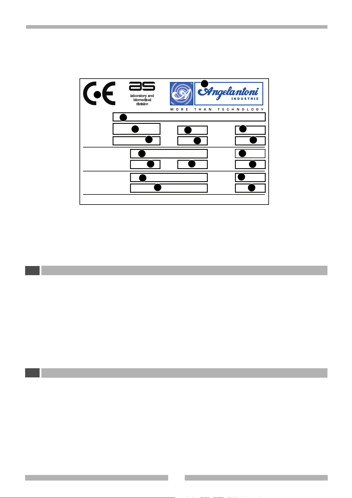
1 RIEPILOGO DEI DATI DI MARCATURA
I
3
4
V~
10
P Kw A Class
n. 1
15
n. 2
COUNTRY OF ORIGIN: ITALY
Year
6
11
16
5
Weight kg
7
Hz
12
Pmax kPa
Pmax kPa
8
9
13
14
17
18
• Localizzate la targa apposta alla macchina per rilevare i dati tecnici.
•Verificate il modello della macchina e la tensione di alimentazione prima di compiere qualsiasi operazione.
• Se rilevate delle discordanze contattate suabito il produttore o l'azienda che ha effettuato la fornitura.
1 Marchio di conformità CE
2 Marchio e indirizzo del fabbricante
3 Modello
4 Numero di serie
5 Anno di costruzione
6 Temperatura
7 Umidità relativa
8 Peso
1 SUMMARY OF RATING PLATE DATA
GB
9 Grado di protezione elettrica
10 Tensione di alimentazione
11 Potenza assorbita
12 Assorbimento elettrico
13 Frequenza
14 Classe di isolamento
15-16 Tipo di refrigerante
17-18 Pressione refrigerante
• Find the special rating plate on the machine in order to check the technical data.
• Check the machine model and supply voltage before carrying out any operation whatsoever.
• If you find any discrepancies, contact the manufacturer or your supplier immediately.
1 EC compliancy mark
2 Manufacturer’s address
3 Model
4 Serial N
5 Year of manufacture
6 Temperature
7 Relative humidity
8Weight
°
9 Electrical protection grade
10 Supply voltage
11 Absorbed power
12 Electrical absorption
13 Frequency
14 Isolation class
15-16 Type of refrigerant
17-18 Pressure of refrigerant
513417
2

2AVVERTENZE
I
2.1 AVVERTENZE GENERALI
• Non effettuate operazioni o manovre se non siete assolutamente certi del loro effetto; in caso di dubbio contattate il servizio di assistenza tecnico più vicino o direttamente il produttore.
• Il produttore si ritiene sollevato da ogni responsabilità per danni
causati alla macchina o alle cose nei casi seguenti:
- uso improprio della macchina
- impiego di personale non idoneo
- montaggio e installazione non corretti
- difetti negli impianti
- modifiche o interventi non autorizzati alla macchina
- utilizzo di parti di ricambio non originali
- inosservanza delle norme dettate nel presente manuale
-eventi eccezionali
• Il presente manuale di istruzioni si rivolge ai seguenti soggetti:
- Addetti del trasporto, movimentazione e disimballo
- Addetti alla preparazione degli impianti e del sito di installazione
- Installatori
- Addetti all'uso della macchina
- Addetti alla manutenzione
• Il manuale di istruzioni indica l'utilizzo previsto dal f abbricante e non può mai sostituire un’adeguata esperienza dell’operatore, può costituire solo un promemoria delle principali operazioni da svolgere.
• Il manuale di istruzioni deve essere conservato con la massima cura e reso sempre disponibile per la consultazione. Se
necessario fotocopiate le pagine che destinerete all'uso diretto sulla macchina. Il manuale de ve a vere una durata alme-
no pari a quella della macchina.
• Il manuale di istruzioni rispecchia la tecnica al momento della
costruzione della macchina; il produttore si riserva il diritto di
apportare tutte le modifiche ritenute opportune, alle macchine e ai manuali di istruzione, senza obbligo di preavviso o di
sostituzione.
In caso di smarrimento o distruzione del manuale è possibile
richiederne una copia apponendo, nella richiesta, i dati di
marcatura (vedi cap1).
La presente macchina non è contemplata nell’allegato IV
delle normative comunitarie sulle macchine, pertanto è
applicata la procedura di cui all’articolo 8, paragrafo 2,
lettera A, delle normative comunitarie sulle macchine 89/
392/CEE e 91/368/CEE. L’articolo 8, paragrafo 2, lettera A
delle normative comunitarie sulle macchine 89/392/CEE e
91/368/CEE obbliga il costruttore a realizzare il fascicolo
previsto dall’allegato delle sopracitate leggi, realizzato e
conservato nell’archivio tecnico della ditta Angelantoni
Industrie spa località Cimacolle Massa Martana Perugia.
2 WARNINGS
GB
2.1 GENERAL WARNINGS
• Do not carry out any operations or manoeuvres unless you
are absolutely certain of their effect; if in doubt, contact your
nearest technical assistance service or the manufacturer
himself.
• The manufacturer will not be held responsible f or damage to
the machine or to objects in the following cases:
- improper use of the machine
- use of unsuitable personnel
- incorrect assembly and installation
- defects in the plant systems
- unauthorized modifications or operations to the machine
- use of spare parts that are not original pieces
-failure to comply with the norms given in this handbook
-exceptional events
• This instruction handbook has been designed for the following
personnel:
-Personnel in charge of transport, handling and removal
of packaging
-Personnel in charge of the preparation of the plant
systems and installation site
- Installers
-Personnel in charge of using the machine
-Personnel in charge of maintenance
• The instruction handbook indicates the use foreseen by the
manufacturer and cannot ever replace adequate experience
of the operator. It can only be used as a reminder of the main
operations to be carried out.
• The instruction handbook should be kept carefully and should
also be within easy reach for reference. If necessary,
photocopy the pages concerned directly with machine use.
The handbook should last at least the life-time of the machine
itself.
• The instruction handbook gives technical information on how
the machine is manufactured at the present time; the
manufacturer reserves the right to carry out any modifications
he deems necessary to the machines and to the instruction
handbooks, without prior notice or replacement.
If you lose or destroy the handbook, y ou may ask for a copy.
Please give the rating plate data (see chap. 1) in y our request.
This machine is not referred to in enclosure IV of the
community norm on machines, and therefore the procedure in article 8, paragraph 2, letter A in the Community
norms for machines 89/392/CEE and 91/368/EEC has been
applied. Article 8, paragraph 2, letter A of the Community
norms for machines 89/392/CEE and 91/368/EEC obliges
the manufacturer to provide the file foreseen by the
enclosure of the afore-mentioned laws, and to store it in
the technical archives of the company Angelantoni Industrie spa, località Cimacolle, Massa Martana, Perugia.
3
513417

2AVVERTENZE
I
2.2 AVVERTENZE PER IL TRASPORTO E LA MOVIMENTAZIONE
• Questo simbolo, apposto su ciascun imballo indica il peso di ogni collo. Occorre sempre verificare che gli attrezzi e le
macchine atte alla movimentazione e trasporto siano adeguate.
• Mantenete sempre la macchina in posizione verticale. Se accidentalmente la macchina è stata capovolta o coricata
non avviatela ma ponetela in posizione corretta e contattate il produttore.
2.3 AVVERTENZE PER L'INSTALLAZIONE
• L'installazione deve essere effettuata da personale specializzato.
• Occorre eseguire scrupolosamente le procedure per la realizzazione degli impianti prima di installare la macchina.
• In fase di predisposizione del sito di installazione tenete conto dello spazio e delle condizioni di lav oro del personale addetto in
modo da ridurre al massimo la rumorosità, l'affaticamento, il disagio e quant'altro possa influire negativamente sulle persone.
• Nel prevedere il luogo di installazione tenete conto di lasciare sufficiente spazio per il controllo, la manutenzione, la pulizia e
l'asporto dei residui di materiale scarto di lavorazione.
• Provvedete ad illuminare adeguatamente il posto di lavoro in modo che il personale addetto si trovi nelle migliori condizioni
operative.
• Nel definire il punto di installazione riferitevi alle normative vigenti e in particolare:
- attuate tutti i dispositivi antincendio e di sicurezza.
2.4 AVVERTENZE PER IL PERSONALE ADDETTO
• La macchina può essere utilizzata solo da parte di personale che abbia preso completa visione delle norme descritte nel
presente manuale.
•L’apertura della camera a temperature molto diverse da quelle ambientali può causare inconvenienti:se la temper atur a interna
è molto bassa possono generarsi fenomeni di condensa e brinatura a causa dell’umidità ambiente.
Frequenti aperture della porta in queste condizioni potranno generare ostruzione degli scambiatori termici.
2 WARNINGS
GB
2.2 WARNINGS FOR TRANSPORT AND HANDLING
• This symbol, placed on each packaging, indicates the weight of each package.
Always check that the tools and machines to handle and transport the machine are adequate.
• Always keep the machine in an upright position. If the machine should accidentally turn upside-down or on its side, do
not switch it on. Put it in the correct position and contact the manufacturer.
2.3 WARNINGS FOR INSTALLATION
• Installation should always be carried out by specialized personnel.
• Carefully follow the instructions on how to prepare the plant systems before installing the machine.
• When the installation site is being prepared, bear in mind the space and work conditions of the personnel in charge of the
machine so as to reduce to a minimum noise, fatigue, discomf ort and anything else which may ha v e a negative influence on the
staff.
• When designing the installation site, remember to leave sufficient space for control, maintenance, cleaning, and removal of
production waste material.
• Make sure that the work site is adequately lit so that personnel can work in optimum conditions.
• When designing the installation site, please refer to the norms in force and in particular:
- set up all the firefighting and safety devices.
2.4 WARNINGS FOR PERSONNEL IN CHARGE OF THE MACHINE
• The machine may only be used by personnel who have read the rules described in this handbook.
•To open the chamber when its temperature is very different from the ambient temperature could cause problems: if the internal
temperature is very low , condensate and frosting could be caused b y ambient humidity. If the door is often opened under these
conditions, the heat exchangers could be obstructed.
513417
4
2AVVERTENZE
3 41 2
2.5 AVVERTENZE PER LA MANUTENZIONE
• Scollegate sempre la macchina dalla rete elettrica prima di
effettuare qualsiasi operazione di manutenzione.
•Per la pulizia delle parti verniciate non utilizzate solventi o
alcool in quanto tali prodotti possono danneggiare le superfici.
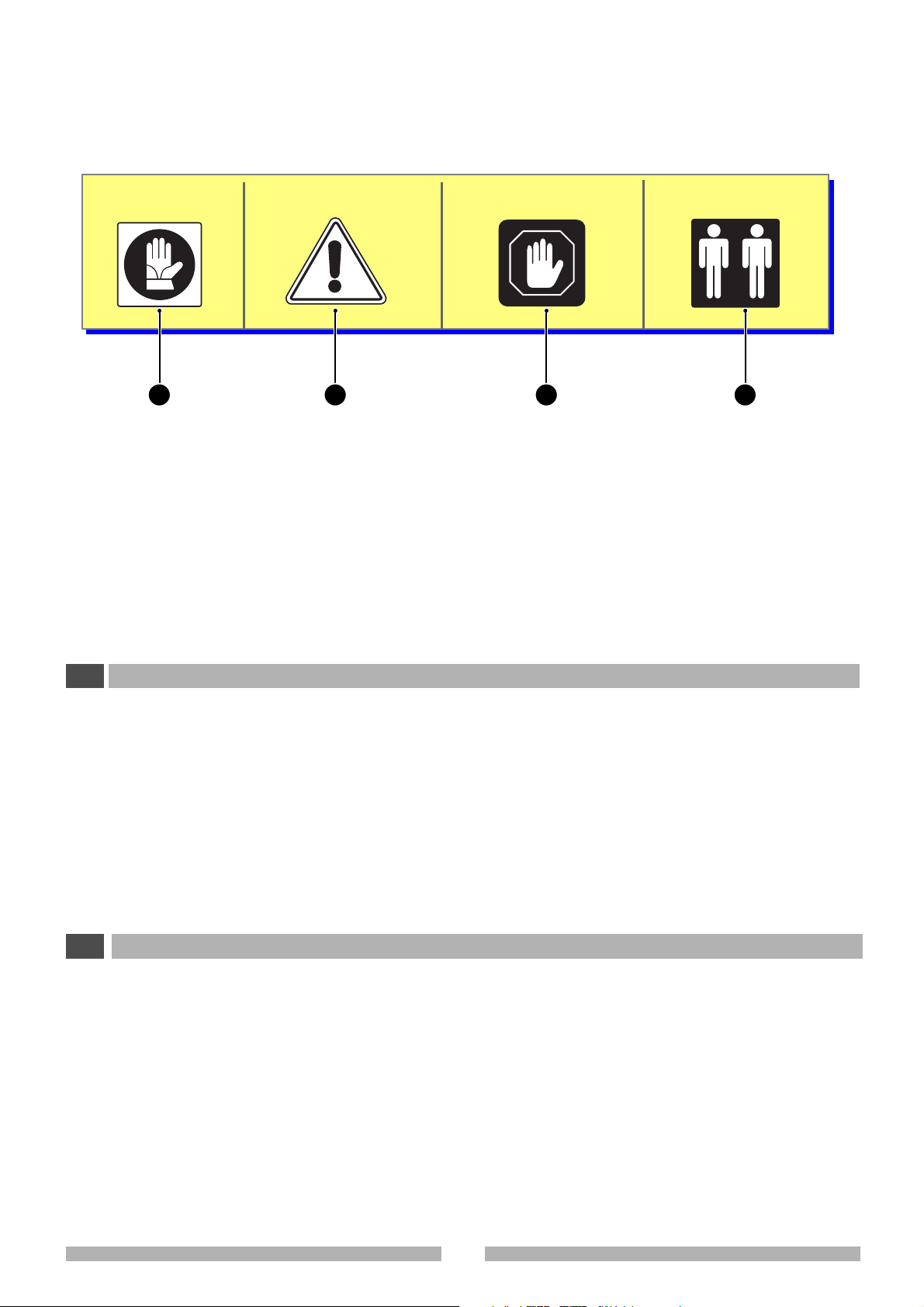
2.6 SPIEGAZIONE DEI SIMBOLI
•I simboli mostrati possono trovarsi sulla macchina o all'interno del presente manuale di istruzioni.
•Ponete attenzione al loro significato prima di procedere.
2 WARNINGS
2.5 WARNINGS FOR MAINTENANCE
• Always disconnect the machine from the electrical mains
before carrying out any maintenance operation.
• Do not use solvents or alcohol to clean the varnished parts
as these products could damage the surface.
2.6 EXPLANATION OF SYMBOLS
• The symbols shown below may be found on the machine or
in this instruction handbook.
•Pay attention to their meaning before going any further.
1 Uso di guanti
2 PERICOLO GENERICO
Questo simbolo è sempre accompagnato
dalla spiegazione del pericolo
3 ATTENZIONE!
Nota importante
4 Operazioni che devono essere compiute
da almeno due persone.
1 Use gloves
2 GENERAL DANGER
This symbol is always accompanied by an
explanation of the danger
3 WARNING
Important nore
4 Operations that must be carried out by
at least two people
5
513417
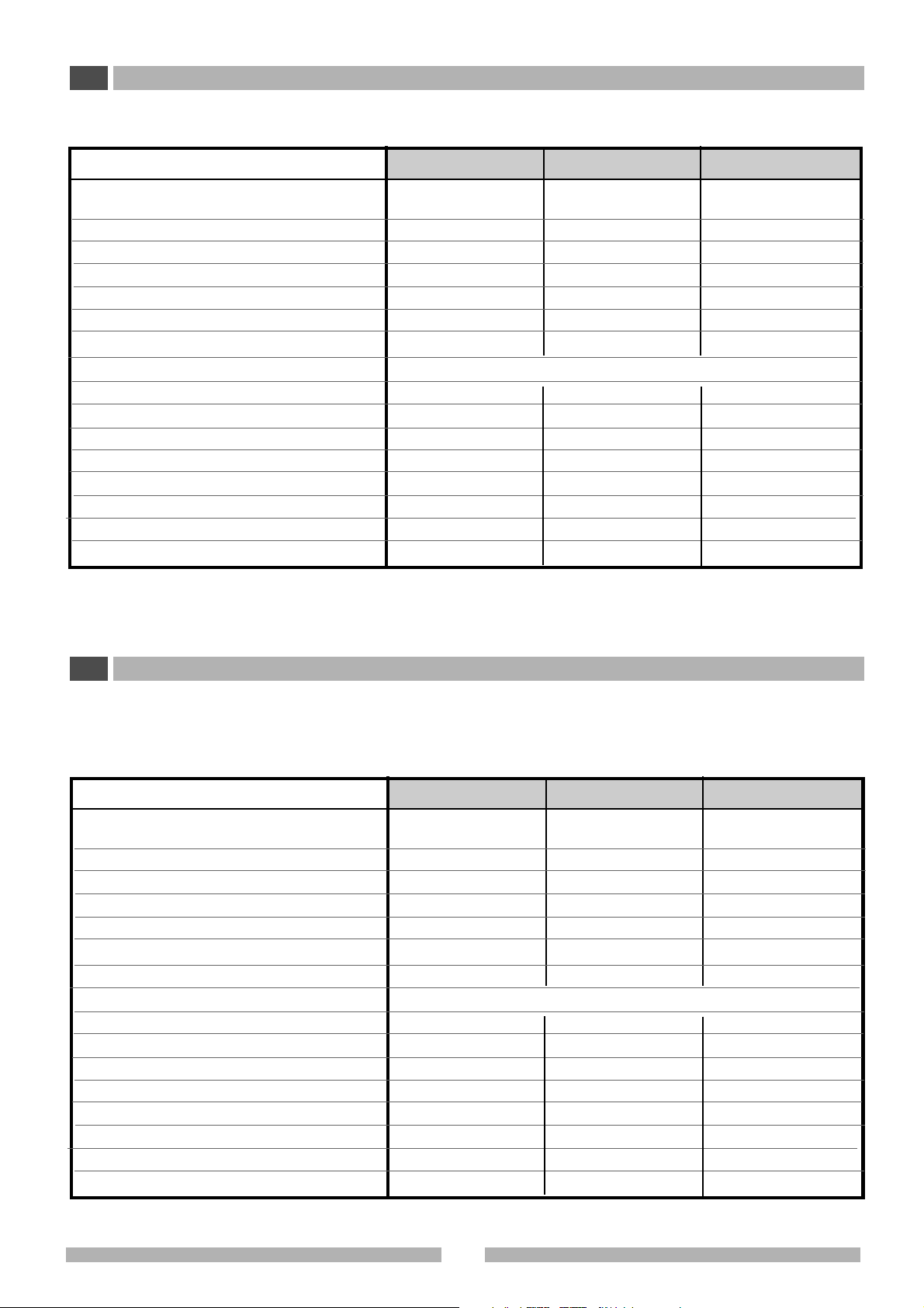
3 CARA TTERISTICHE TECNICHE
I
3.1 DATI TECNICI
Modelli
Dimensione esterne (L x P x H) (3) (mm)
Dimensione interne (L x P x H) (mm)
Volume utile (l)
Temperatura di esercizio (°C)
Campo di temperatura (°C)
Precisione temperatura nello spazio (± °C) (1) (IEC 68)
Precisione temperatura nel tempo (± °C) (1) (IEC 68)
Gas refrigerante (2)
Alimentazione elettrica
Corrente massima assorbita (A)
Consumo energetico (kW/24h)
Rumorosità (dB(A)
Dissipazione termica (kcal/h)
Peso netto con accessori in dotazione (kg)
Peso netto + pannello aggiuntivo (kg)
Peso con imballo in cartone + pedana (kg)
Peso netto + pannello aggiuntivo (kg)
RL 180 S
602 x 600 x 850
513 x 433 x 734
180
+4
+2 ÷ 12
±2
±2
R134a - R600a
1
1,2
48
55
44
48
50
54
RL 260 S
602 x 600 x 1220
513 x 433 x 1047
260
+4
+2 ÷ 12
±2
±2
R134a - R600a
230 V (+6/-10 %) / 50 (60) Hz
1,2
1,4
48
90
54
58
60
64
(4)
/ 1 + T
RL 500 S
755 x 715 x 1520
646 x 516 x 1338
500
+4
+2
÷ 12
±2,5
±2
R134a - R600a
1,3
1,2
48
75
75
79
83
87
3TECHNICAL SPECIFICATIONS
GB
3.1 TECHNICAL DATA
Models
External dimensions (W x D x H) (3) (mm)
Internal dimensions (W x D x H) (mm)
Useful volume (l)
Operative temperature (°C)
Temperature range (°C)
Temperature accuracy in space (± °C) (1) (IEC 68)
Temperature accuracy in time (± °C) (1) (IEC 68)
Refrigerant gas (2)
Electrical input
Maximum absorbed current (A)
Energy consumption (kW/24h)
Noise level (dB(A))
Thermal dissipation (kcal/h)
Net weight with standard accessories (kg)
Net weight with additional panel (kg)
Weight with cardboard packaging + board (kg)
Net weight with additional panel (kg)
RL 180 S
602 x 600 x 850
513 x 433 x 734
180
+4
+2 ÷ 12
±2
±2
R134a - R600a
1
1,2
48
55
44
48
50
54
RL 260 S
602 x 600 x 1220
513 x 433 x 1047
260
+4
+2 ÷ 12
±2
±2
R134a - Ra600a
230 V (+6/-10 %) / 50 (60) Hz
1,2
1,4
48
90
54
58
60
64
(4)
/ 1 + G
RL 500 S
755 x 715 x 1520
646 x 516 x 1338
500
+4
+2 ÷ 12
±2,5
±2
R134a - R600a
1,3
1,2
48
75
75
79
83
87
513417
6
I
Modelli
Dimensione esterne (L x P x H) (3) (mm)
Dimensione interne (L x P x H) (mm)
Volume utile (l)
Temperatura di esercizio (
Campo di temperatura (°C)
Precisione temp. nello spazio (1) (IEC 68) (±°C)
1
Precisione temp. nel tempo (
Gas refrigerante (2)
Alimentazione elettrica
Corrente massima assorbita (A)
Consumo energetico (kW/24h)
Rumorosità (dB(A)
Dissipazione termica (kcal/h)
Peso netto con accessori in dotazione (kg)
Peso netto + pannello aggiuntivo (kg)
Peso con imballo in cartone + pedana (kg)
Peso netto + pannello aggiuntivo (kg)
) (IEC 68) (± °C)
°C)
FRL 180V
602 x 600 x 885
513 x 433 x 734
180
+4
+2
÷ 12
1,5
1
R134a - R600a
1
1,4
48
70
47
51
55
59
FRL 180V -GL
602 x 600 x 885
513 x 433 x 734
180
+4
+2 ÷ 12
1,5
1
R134a - R600a
230 V (+6/-10 %) / 50 (60) Hz
1
1,6
48
80
54
58
62
66
602 x 600 x 1220
513 x 433 x 1047
R134a - R600a
FRL 260V
260
+4
+2
÷ 12
1,5
1
(4)
/ 1 + T
1,1
1,7
48
80
54
58
62
66
FRL 260V -GL
602 x 600 x 1220
513 x 433 x 1047
260
+4
+2
÷ 12
1,5
1
R134a - R600a
1,1
1,9
48
85
65
69
73
77
GB
Models
External dimensions (W x D x H) (3) (mm)
Internal dimensions (W x D x H) (mm)
Useful volume (l)
Operative temperature (°C)
Temperature range (°C)
Temperature accuracy in space (± °C) (1) (IEC 68)
Temperature accuracy in time (± °C) (1) (IEC 68)
Refrigerant gas (2)
Electrical input
Maximum absorbed current (A)
Energy consumption (kW/24h)
Noise level (dB(A))
Thermal dissipation (kcal/h)
Net weight with standard accessories (kg)
Net weight with additional panel (kg)
Weight with cardboard packaging + board (kg)
Net weight with additional panel (kg)
FRL 180V
602 x 600 x 885
513 x 433 x 734
180
+4
+2 ÷ 12
1,5
1
R134a - R600a
1
1,4
48
70
47
51
55
59
FRL 180V -GL
602 x 600 x 885
513 x 433 x 734
180
+4
+2 ÷ 12
1,5
1
R134a - R600a
230 V (+6/-10 %) / 50 (60) Hz
1
1,6
48
80
54
58
62
66
602 x 600 x 1220
513 x 433 x 1047
R134a - R600a
FRL 260V
260
+4
+2
÷ 12
1,5
1
(4)
/ 1 + G
1,1
1,7
48
80
54
58
62
66
FRL 260V -GL
602 x 600 x 1220
513 x 433 x 1047
260
+4
+2 ÷ 12
1,5
1
R134a - R600a
1,1
1,9
48
85
65
69
73
77
7
513417
I
Modelli
Dimensione esterne (L x P x H) (3) (mm)
Dimensione interne (L x P x H) (mm)
Volume utile (l)
Temperatura di esercizio (°C)
Campo di temperatura (°C)
Precisione temp. nello spazio (1) (IEC 68) (±°C)
Precisione temp. nel tempo (
Gas refrigerante (2)
Alimentazione elettrica
Corrente massima assorbita (A)
Consumo energetico (kW/24h)
Rumorosità (dB(A)
Dissipazione termica (kcal/h)
Peso netto con accessori in dotazione (kg)
Peso netto + pannello aggiuntivo (kg)
Peso con imballo in cartone + pedana (kg)
Peso netto + pannello aggiuntivo (kg)
1
) (IEC 68) (± °C)
FRL 360V
602 x 600 x 1600
513 x 433 x 1418
360
+4
+2 ÷ 12
1,5
1
R134a - R600a
1,1
1,7
48
85
64
68
72
76
FRL 360V -GL
602 x 600 x 1600
513 x 433 x 1418
360
+4
+2 ÷ 12
1,5
1
R134a - R600a
230 V (+6/-10 %) / 50 (60) Hz
1,2
2,2
48
90
80
84
92
96
755 x 715 x 1520
646 x 516 x 1338
FRL 500V
500
+4
+2 ÷ 12
1
1,5
R134a - R600a
(4)
/ 1 + T
1,4
1,6
48
90
78
82
86
90
FRL 500V -GL
755 x 715 x 1520
646 x 516 x 1338
500
+4
+2 ÷ 12
1
1,5
R134a - R600a
1,4
2,5
48
100
95
99
103
107
GB
Models
External dimensions (W x D x H) (3) (mm)
Internal dimensions (W x D x H) (mm)
Useful volume (l)
Operative temperature (°C)
Temperature range (°C)
Temperature accuracy in space (± °C) (1) (IEC 68)
Temperature accuracy in time (± °C) (1) (IEC 68)
Refrigerant gas (2)
Electrical input
Maximum absorbed current (A)
Energy consumption (kW/24h)
Noise level (dB(A))
Thermal dissipation (kcal/h)
Net weight with standard accessories (kg)
Net weight with additional panel (kg)
Weight with cardboard packaging + board (kg)
Net weight with additional panel (kg)
FRL 360V
602 x 600 x 1600
513 x 433 x 1418
360
+4
+2 ÷ 12
1,5
1
R134a - R600a
1,1
1,7
48
85
64
68
72
76
FRL 360V -GL
602 x 600 x 1600
513 x 433 x 1418
360
+4
+2 ÷ 12
1,5
1
R134a - R600a
230 V (+6/-10 %) / 50 (60) Hz
1,2
2,2
48
90
80
84
92
96
755 x 715 x 1520
646 x 516 x 1338
FRL 500V
500
+4
+2 ÷ 12
1
1,5
R134a - R600a
(4)
/ 1 + G
1,4
1,6
48
90
78
82
86
90
FRL 500V -GL
755 x 715 x 1520
646 x 516 x 1338
500
+4
+2 ÷ 12
1
1,5
R134a - R600a
1,4
2,5
48
100
95
99
103
107
513417
8

3
D = 175 mm
D
513427-010
P
I
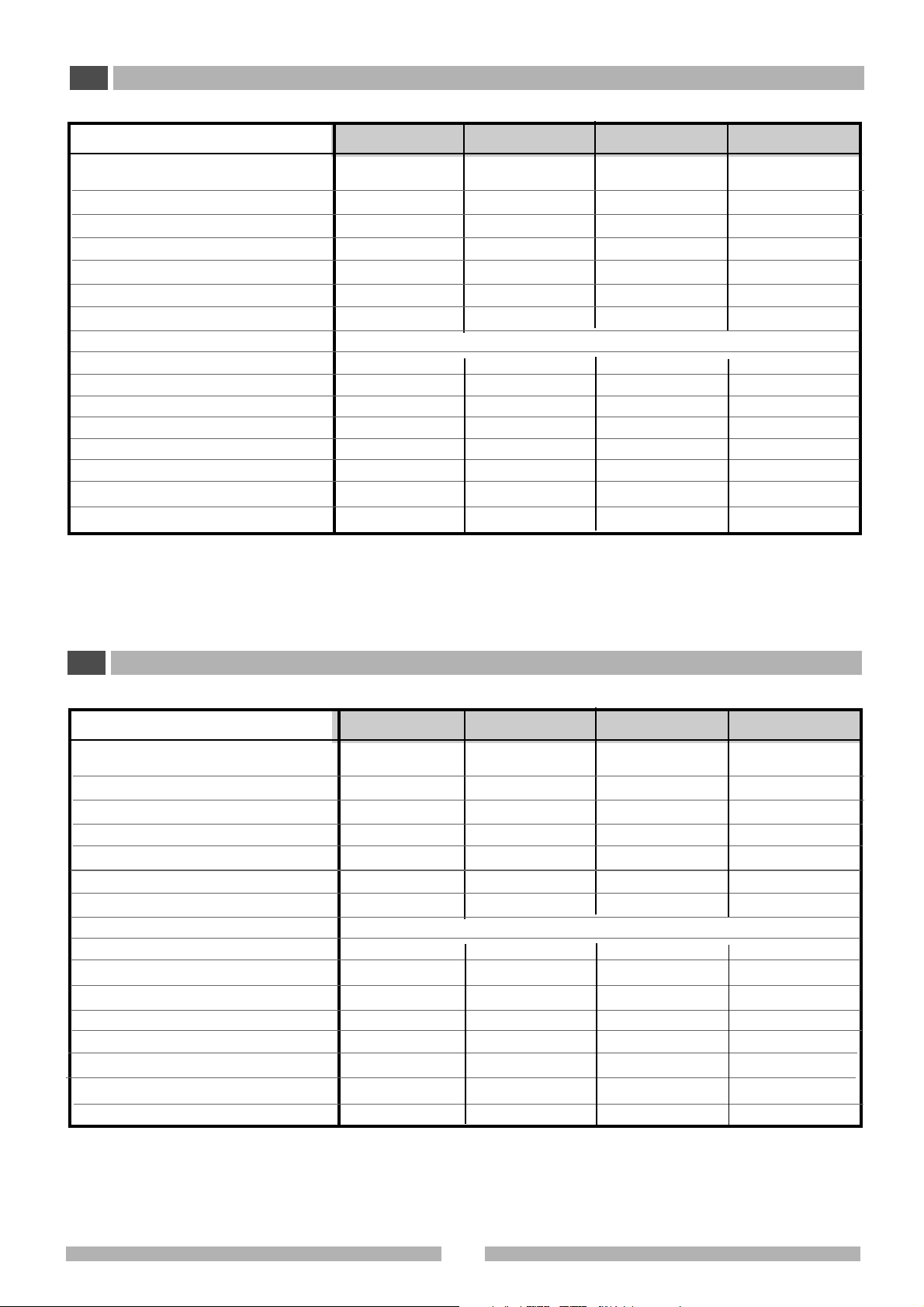
(1) La prova è effettuata collegando le termocoppie (tipo T) ad una
massa avente le seguenti caratteristiche:
- materiale: lega di alluminio
- capacità termica: 102 J/K
- superficie esterna: 0,009 m
Sono posizionate ad una distanza di L/10 dalle pareti della camera
(L= lunghezza del lato della camera), secondo IEC 60068-3-5.
- Fluttuazione di temperatura nel tempo:
massima deviazione fra il valore massimo e minimo misurato da
ciascuna sonda (valore di riferimento = valore medio nel punto
considerato).
2
GB
(1) The test is carried out by connecting the thermal couplings (type T)
to a mass with the following characteristics:
- material: aluminium alloy
- thermal capacity: 102 J/K
- external surface: 0.009 m
They are positioned at a distance of L/10 from the room walls (L =
length of room side), according to IEC 60068-3-5.
2
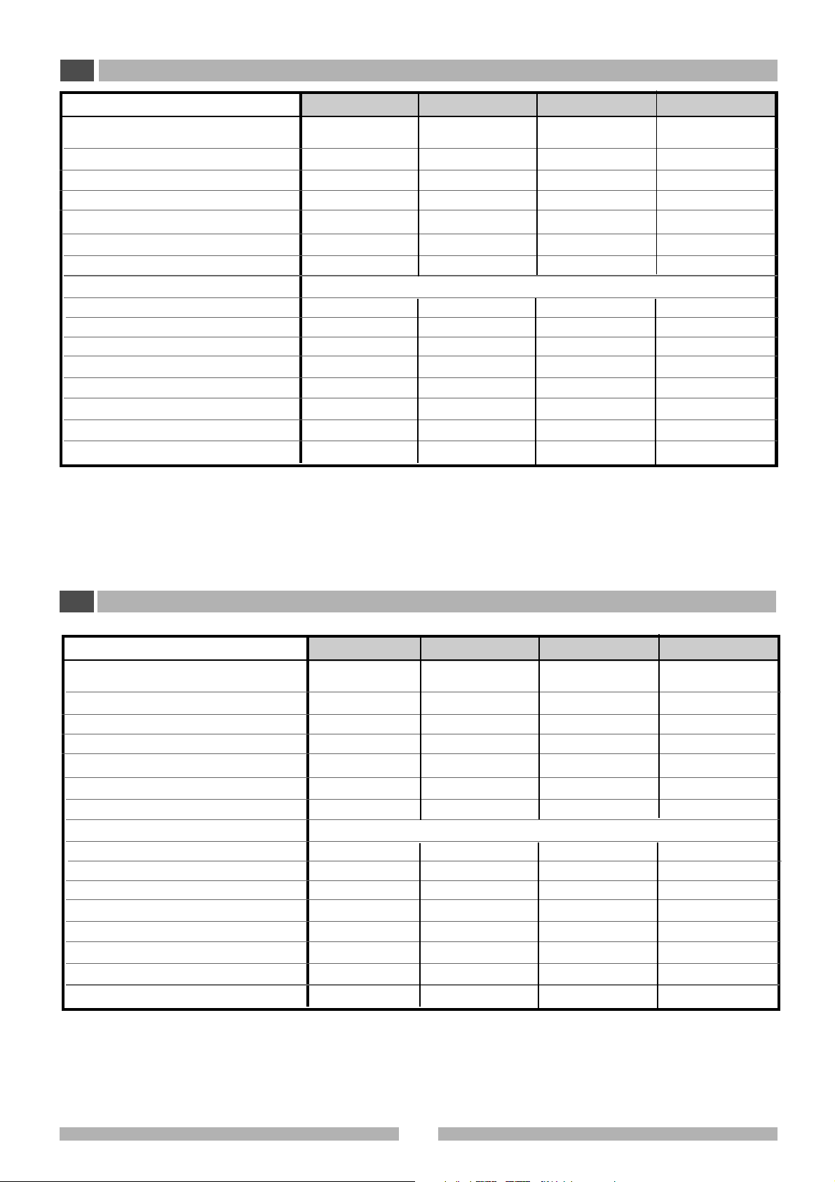
- Variazione di temperatura nello spazio:
massima deviazione fra i valori medi misurati dalle 9 sonde (valore di
riferimento = valore di set-point).
(2) Per il tipo di gas refrigerante vedere targa dati.
(3) Per le apparecchiature con pannello aggiuntivo (P) l’altezza del
congelatore aumenta di 175 mm.
(4) Vedi dati di targa.
-
Temperature fluctuations over time
the lowest and highest value measured by each sensor (reference
value= mean value at the point under study).
-
Temperature variations inside the space
between the mean values measured by the 9 sensors (reference
value = set-point value).
(2) For the type of refrigerant, see the rating plate.
(3) For appliances with the additional panel (P) the freezer height
increases by 175 mm.
(4) See rating plate data.
: maximum difference between
: maximum difference
9
513417
3.1
20°C
PO1207-130
3 CARATTERISTICHE TECNICHE
I
3.2 FUSIBILI
40°C
PO1207-140
TUTTI I MODELLI (con pannello aggiuntivo)
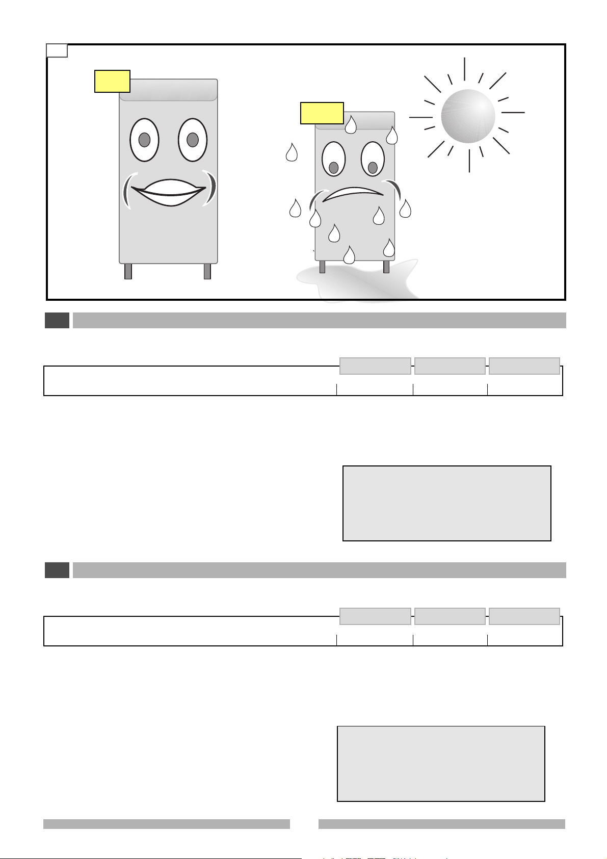
3.3 CONDIZIONI AMBIENTALI
Per il corretto funzionamento dell’apparecchiatura è necessario che il posizionamento rispetti i seguenti requisiti:
• lontano da fonti di calore,
• lontano dai raggi diretti del sole,
• lontano dai sistemi di condizionamento,
• ambiente non polveroso.
3 TECHNICAL SPECIFICATIONS
GB
3.2 FUSES
ALL MODELS (with additional panel)
Simbolo Valore Codice
FUSE
6 A TT
Temperatura ambiente min: +10°C (*)
max + 30°C
Umidità relativa UR max 80%
(*) La temperatura ambiente non deve essere infe
riore al set point impostato.
Symbol Value Code
FUSE
6 A TT
3.3 ENVIRONMENTAL CONDITIONS
In order for the appliance to operate correctly , it should be placed
in a site with the following requisites:
•far from heat sources,
•far from direct sunlight,
•far from air conditioning systems,
• in a dust-free ambient.
513417
Ambient temperature min: +10°C (*)
max + 30°C
Relative humidity RH max 80%
(*) The ambient temperature must not be inferior to
the chosen set-point.
10
 Loading...