

Angelantoni Industrie POLAR 180 SH, POLAR 370 H, POLAR 550 SH, POLAR 110 H, POLAR 110 SH Service manual [en, it]
...
FREEZERS
POLAR 110 H / POLAR 110 SH
POLAR 180 H / POLAR 180 SH
POLAR 370 H / POLAR 370 SH
POLAR 340 V / POLAR 340 SV
POLAR 530 V / POLAR 530 SV
POLAR 550 H / POLAR 550 SH
iso 9001
nato aqap110
PO1207-F01
iso 14001
PO1207-F17
Installation, use and maintenance handbook
Angelantoni Industrie S.p.A.
06056 Massa Martana (Pg) Italy
Tel. (++39) 075.8955.1 (a.r.)
Fax (++39) 075.8955200
Internet: www.angelantoni.it
E-Mail:info@angelantoni.it
Cod. 513005 - Rel. 080503

464 Località Cimacolle
06056 Massa Martana (Pg) Italy
AVVERTENZA IMPORTANTE
I prodotti realizzati dal costruttore sono caratterizzati da un elevato contenuto tecnologico che talvolta richiede
un adattamento tecnico di parti o componenti altrimenti reperibili sul mercato nella loro versione standard
commerciale. Pertanto, la sostituzione di parti o componenti con altri non originali, ossia non forniti e garantiti
direttamente dal COSTRUTTORE, nonché l’accertamento di interventi tecnici effettuati da personale non autorizzato,
comporteranno l’immediata cessazione della garanzia, se in essere, e comunque di qualsiasi responsabilità nei
confronti dell’acquirente e di terzi, da parte del COSTRUTTORE stesso.
IMPORTANT WARNING
The high level of technology of the products made by the manufacturer occasionally requires components to be
adapted from parts normally found on the market in their standard commercial version. Therefore, if it should be
ascertained that any parts have been replaced with other components that are not original, i.e. that have not
been supplied and guaranteed directly by the MANUFACTURER, or that any unauthorised technical interventions
have been carried out, the guarantee, if any is in force, shall be considered no longer valid and the MANUFACTURER
himself shall no longer be held responsible towards the purchaser and towards third parties.
AVVERTISSEMENT IMPORTANT
Les produits réalisés par le constructeur sont caractérisés par un haut niveau technologique qui demande parfois
une adaptation technique de parties ou de composants autrement disponibles sur le marché dans leur version
commerciale standard. Pour cette raison, la substitution de parties ou composants par d’autres non originaux,
c’est à dire non fournis et garantis directement par le CONSTRUCTEUR, ou bien la constatation que du personnel
non autorisé a effectué des interventions techniques; auront pour conséquence l’immédiate cessation de la garantie
en cours et de toute façon de toutes responsabilités du CONSTRUCTEUR vis à vis de l’acheteur ou de tierces
parties.
WICHTIGE WARNUNG
Das hohe technische Niveau der Produkte des Herstellers erfordert teilweise Komponenten, die verändert
werden müssen gegenüber handelsüblichen Produkten␣ ; wie sie am Markt zu finden sind.
Beim Austausch von Teilen oder Komponenten; die nicht dem Orginal entsprechen, das heißt nicht direkt vom
HERSTELLER geliefert und garantiert wurden, bzw. daß technische Veränderungen durch nicht autorisiertes
Personal vorgenommen wurde, gilt die Garantie, falls noch in Kraft, als erloschen und der HERSTELLER kann
nicht mehr länger haftbar gemacht werden gegenüber dem Käufer und Dritten.
AVISO IMPORTANTE
Los productos elaborados por el fabricante se caracterizan por un alto nivel tecnológico y ocasionalmente
requieren adaptaciones técnicas de partes o componentes que normalmente se encuentran en el mercado en
su versión comercial estándar.
Por tanto, la sustitución de partes o componentes, por otros que no sean originales, es decir no suministrados
y garantizados por el FABRICANTE, o bien se constata la intervención técnica por de personal no autorizado,
supondrá el cese inmediato de la garantía, si está en vigor, así como de cualquier otra responsabilidad del
FABRICANTE de cara tanto al comprador como a terceras personas.
464 Località Cimacolle
06056 Massa Martana (Pg) Italy
DICHIARAZIONE DI CONFORMITÀ
DECLARATION OF CONFORMITY
Denominazione prodotto:POLAR
Product Name
Costruttore
Manufacturer
La macchina è conforme ai dettami delle seguenti
Direttive CEE:
• Direttiva Macchine n° 98/37, successive modifiche
e DPR 459/96.
• Direttiva Bassa Tensione n° 73/23 e successive
modifiche.
• Direttiva Compatibilità Elettromagnetica n° 89/336
e successive modifiche.
In particolare soddisfa le seguenti Norme
Armonizzate:
Ordine / Serie N.
Order/series N
Mandatario
Agent
°
The machine complies with the regulations in the
following EEC Directives:
• Machinery Directive n° 98/37, subsequent modifications and DPR 459/96.
• Low Voltage Directive n° 73/23 and subsequent
modifications.
• Electromagnetic Compatibility Directive n° 89/336
and subsequent modifications.
In particular it complies with the following
Standardized Norms:
• EN 292-1 Sicurezza del macchinario - Concetti
fondamentali, principi generali di progettazione Parte 1: Terminologia, metodologia di base. 1991.
• EN 292-2 Sicurezza del macchinario - Concetti
fondamentali, principi generali di progettazione Parte 2: Specifiche e principi tecnici. 1991.
• EN 294 Sicurezza del macchinario - Distanza di
sicurezza per impedire il raggiungimento di zone
pericolose con gli arti superiori. 1992
• EN 61326-1 Apparecchi elettrici di misura, controllo e laboratori. Prescrizioni di compatibilità elettromagnetica. - Parte 1: Prescrizioni generali e successive modifiche.
• EN 61010-1 Prescrizioni di sicurezza per apparecchi elettrici di misura, controllo e per utilizzo in
laboratorio - Parte 1: Prescrizioni generali.
Data
Date
• EN292-1 Safety of machinery - Fundamental concepts, general principles for design - Part 1: Terminology, basic methodology, 1991.
• EN292-2 Safety of machinery - Fundamental concepts, general principles for design - Part 2: Technical specifications and principles. 1991.
• EN294 Safety of machinery - Safety distance to
prevent upper limbs coming into contact with dangerous areas. 1992.
• EN61326-1 - Electrical equipment for measurement, control and laboratory use EMC requirements
- Part. 1 - General requirements.
• EN61010-1 Safety instructions for electrical apparatus to measure, and control and for laboratory
use - Part 1: General instructions.
L’amministratore delegato
Managing Director
Gianluigi Angelantoni
DICHIARAZIONE DI CONFORMITÀ
DECLARATION OF CONFORMITY
Modello:POLAR
Type
Da (Fornitore)
From (Supplier)
ANGELANTONI INDUSTRIE S.p.A.
Loc. Cimacolle
06056 Massa Martana (Pg) - Italia
Si certifica che la totalità delle forniture sopraelencate
è conforme in ogni parte alle specifiche, ai disegni e
all’ordine cui si riferiscono e che le forniture sono state
verificate e provate in conformità con le condizioni ed
i requisiti dell’ordine e in particolare alla Direttiva 93/
42.
Matricola
Serial number
We certify that all the supplies mentioned in this document comply in any detail with the specifications, with
the drawings and with the purchase order refer to.
We also certify that the supplies have been checked and
tested according to the order conditions and requirements
and particularly to 93/42 law.
Data
Date
Firma (Fornitore)
Signature (Supplier)
ANGELANTONI INDUSTRIE S.p.A.
Nome (Stampatello) -
Il Responsabile Qualità -
Dott.ssa -
Miss
Printed name
Quality Manager
Gabriella Parodi

SUMMARY
1SUMMARY OF RATING PLATE DATA ....................................................................................................................................................... 4
2WARNINGS................................................................................................................................................................................................. 4
2.1 GENERAL WARNINGS ...................................................................................................................................................................... 4
2.2 WARNINGS FOR TRANSPORT AND HANDLING ............................................................................................................................ 5
2.3 WARNINGS FOR INSTALLATION ...................................................................................................................................................... 5
2.4 WARNINGS FOR PERSONNEL IN CHARGE OF THE MACHINE .................................................................................................... 5
2.5 WARNINGS FOR MAINTENANCE .................................................................................................................................................... 5
2.6 EXPLANATION OF SYMBOLS........................................................................................................................................................... 5
3 TECHNICAL SPECIFICATIONS................................................................................................................................................................. 6
3.1 TECHNICAL DATA.............................................................................................................................................................................. 6
3.2 FUSES................................................................................................................................................................................................ 7
3.3 ENVIRONMENTAL CONDITIONS...................................................................................................................................................... 7
3.4 TECHNICAL LAY-OUT DIAGRAMS.................................................................................................................................................... 8
4 HANDLING AND REMOVAL OF PACKAGING .......................................................................................................................................... 9
4.1 PERSONNEL REQUISITES............................................................................................................................................................... 9
4.2 MACHINE CONDITIONS.................................................................................................................................................................... 9
4.3 EQUIPMENT NEEDED FOR HANDLING .......................................................................................................................................... 9
4.4 REMOVAL OF PACKAGING............................................................................................................................................................. 11
4.4.1 How to remove the outer straps.............................................................................................................................................. 11
4.4.2 How to remove the cardboard casing..................................................................................................................................... 11
4.4.3 Removal of plastic materials................................................................................................................................................... 11
4.4.4 How to remove the wooden side blocks ................................................................................................................................. 11
4.4.5 How to remove the pallet........................................................................................................................................................ 12
4.5 HOW TO BLOCK THE MACHINE..................................................................................................................................................... 12
5DESCRIPTION OF THE SYSTEM ............................................................................................................................................................ 13
5.1 GENERAL VIEW ................................................................................................................................................................................. 13
5.2 INTERNAL VIEW .............................................................................................................................................................................. 14
5.3 DESCRIPTION OF EXTERNAL CONNECTIONS............................................................................................................................ 15
5.4 CONTROL SYSTEM ........................................................................................................................................................................ 17
5.5 COOLING SYSTEM ......................................................................................................................................................................... 18
5.5.1 CONTROL PANEL - description of the keys........................................................................................................................... 17
5.6 FUNCTIONING OF THE COOLING SYSTEM ................................................................................................................................. 18
5.7 FUNCTIONING OF THE auxiliary CO2 COOLING SYSTEM........................................................................................................... 18
5.8 INSULATION..................................................................................................................................................................................... 18
6INSTALLATION ......................................................................................................................................................................................... 19
6.1 POSITIONING OF THE MACHINE ................................................................................................................................................... 19
6.2 HOW TO CONNECT THE CO2 CYLINDERS................................................................................................................................... 19
6.2.1 HOW TO REPLACE THE CYLINDER .................................................................................................................................... 20
6.3 ELECTRICAL WIRING ..................................................................................................................................................................... 21
6.3.1 How to connect to the electrical mains supply........................................................................................................................ 21
6.3.2 Replacement of the supply cable ........................................................................................................................................... 21
6.3.3 Remote alarm ......................................................................................................................................................................... 22
6.4 Water condenser connection ............................................................................................................................................................ 22
7USE FORESEEN BY THE MANUFACTURER.......................................................................................................................................... 23
7.1 AIM OF THE MACHINES ................................................................................................................................................................. 23
7.2 INTENDED USE OF THE MACHINES ............................................................................................................................................. 23
7.3 OPERATOR ...................................................................................................................................................................................... 23
7.4 USE LIMITS...................................................................................................................................................................................... 23
7.5 USE OF PROTECTIVE CLOTHING ................................................................................................................................................. 23
7.6 DANGEROUS AREAS AND WASTE RISKS.................................................................................................................................... 23
8START-UP ................................................................................................................................................................................................ 24
8.1 DESCRIPTION OF THE CONTROL PANEL .................................................................................................................................... 24
8.2 START UP ........................................................................................................................................................................................ 25
8.3 REGULATION OF THE OPERATING TEMPERATURE ................................................................................................................... 25
8.4 CO2 ALARM SYSTEM ON/OFF....................................................................................................................................................... 26
8.5 REGULATION OF THE ALARM/CO2 SYSTEM TEMPERATURE LIMIT ......................................................................................... 26
8.6 OTHER FUNCTIONS OF CONTROL PANEL .................................................................................................................................. 26
9 USE ................................................................................................................................................................................................ 27
10 SAFETY DEVICES - CHECK AND SET-UP ............................................................................................................................................. 31
11 MAINTENANCE ........................................................................................................................................................................................ 31
12 TROUBLESHOOTING .............................................................................................................................................................................. 33
13 REMOVAL FROM INSTALLATION SITE .................................................................................................................................................. 34
14 DIAGRAMS ............................................................................................................................................................................................... 35
8.6.1 Alarm signals .......................................................................................................................................................................... 26
9.1 HOW TO INSTALL THE DRAWERS (only for vertical models)........................................................................................................ 27
9.2 HOW TO INSTALL THE SHELVES (only for vertical models) ........................................................................................................... 28
9.3 PRODUCT LOADING....................................................................................................................................................................... 28
9.4 TEMPERATURE CHART RECORDER ............................................................................................................................................ 29
9.4.1 Use of the recorder................................................................................................................................................................. 29
11.1 ALARM SYSTEM AND AUXILIARY CO2 COOLING SYSTEM CONTROL ..................................................................................... 31
11.2 DEFROSTING AND CLEANING OF THE STRUCTURE ................................................................................................................. 31
11.3 CLEANING OF GASKETS ............................................................................................................................................................... 31
11.4 CLEANING OF THE CONDENSER ................................................................................................................................................. 32
11.4.1 Cleaning of the water condenser .......................................................................................................................................... 32
11.5 SERVICING OF THE COOLING SYSTEM....................................................................................................................................... 32
11.6 SERVICING OF THE ELECTRIC-ELECTRONIC SECTION............................................................................................................ 32
13.1 DISASSEMBLY ................................................................................................................................................................................. 34
13.2 SCRAPPING..................................................................................................................................................................................... 34
14.1 REFRIGERATOR DRAWING............................................................................................................................................................ 35
14.2 ELECTRIC DRAWING...................................................................................................................................................................... 37
3
513005 POLAR
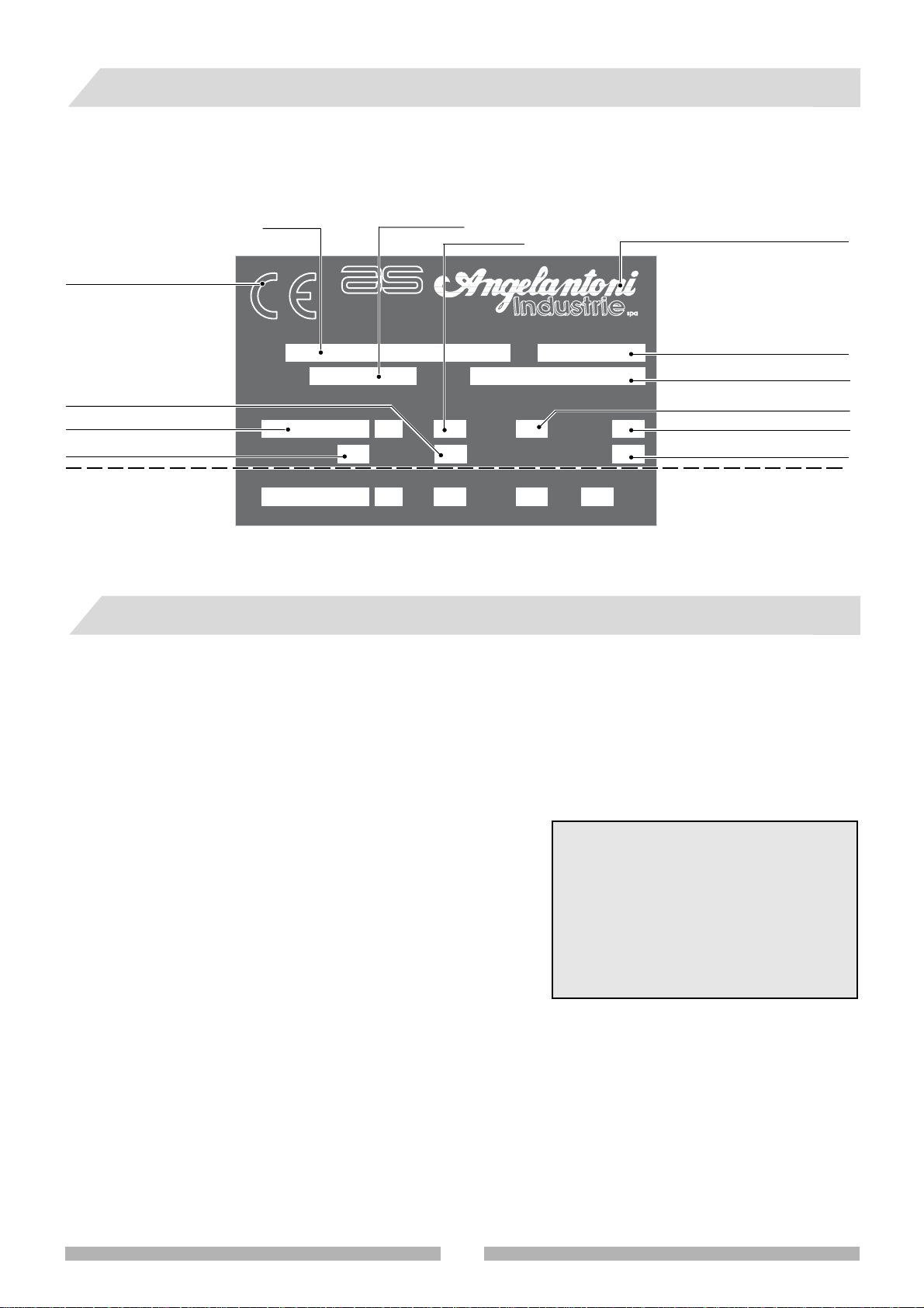
1 SUMMARY OF RATING PLATE DATA
•Find the special rating plate on the machine in order to check the technical data.
• Check the machine model and supply voltage before carrying out any operation whatsoever.
• If you find any discrepancies, contact the manufacturer or your supplier immediately.
Series N°
BIOMEDICAL
DIVISION
Frequency
MASSA MARTANA - PG -
°C
POWER SUPPLY
TYPE
OUTPUT SERVICE POWER SUPPLY
Hz PH
Manufacturer’s address
Temperature
Refrigerant type
Phase
A
IP
Electrical absorption
Electrical protection grade
A
EC compliancy mark
Type (not used)
Supply voltage
Isolation class
Data present only if the
appliance is equipped with
internal sockets.
Model
TYPE
SERIAL N. GAS
VHzPH
CLASS
V
2WARNINGS
2.1 GENERAL WARNINGS
• Do not carry out any operations or manoeuvres unless you are absolutely certain of their effect; if in doubt, contact
your nearest technical assistance service or the manufacturer himself.
• The manufacturer will not be held responsible for damage to the machine or to objects in the following cases:
-improper use of the machine
- use of unsuitable personnel
-incorrect assembly and installation
- defects in the plant systems
- unauthorized modifications or operations to the machine
- use of spare parts that are not original pieces
-failure to comply with the norms given in this handbook
- exceptional events
• This instruction handbook has been designed for the following
personnel:
- Personnel in charge of transport, handling and removal of pack-
aging
- Personnel in charge of the preparation of the plant systems and
installation site
-Installers
- Personnel in charge of using the machine
- Personnel in charge of maintenance
• The instruction handbook indicates the use foreseen by the manufacturer and cannot ever replace adequate
experience of the operator. It can only be used as a reminder of the main operations to be carried out.
• The instruction handbook should be kept carefully and should also be within easy reach for reference. If necessary,
photocopy the pages concerned directly with machine use. The handbook should last at least the life-time of the
machine itself.
• The instruction handbook gives technical information on how the machine is manufactured at the present time; the
manufacturer reserves the right to carry out any modifications he deems necessary to the machines and to the
instruction handbooks, without prior notice or replacement.
This machine is not referred to in enclosure IV of the
community norm on machines, and therefore the procedure in article 8, paragraph 2, letter A in the Community
norms for machines 89/392/CEE and 91/368/EEC has
been applied. Article 8, paragraph 2, letter A of the
Community norms for machines 89/392/CEE and 91/
368/EEC obliges the manufacturer to provide the file
foreseen by the enclosure of the afore-mentioned laws,
and to store it in the technical archives of the company
Angelantoni Industrie spa, località Cimacolle, Massa
Martana, Perugia.
513005 POLAR
4
This handbook should last at least as long as the machine itself. It is, therefore, a good idea to always keep it in its holder.
If you lose or destroy the handbook, you may ask for a copy. Please give the rating plate data (see chap. 1) in your
request.
2.2 WARNINGS FOR TRANSPORT AND HANDLING
• This symbol, placed on each packaging, indicates the weight of each package.
Always check that the tools and machines to handle and transport the machine are adequate.
Kg
•Always keep the machine in an upright position. If the machine should accidentally turn upside-down or
on its side, do not switch it on. Put it in the correct position and contact the manufacturer.
2.3 WARNINGS FOR INSTALLATION
•Installation should always be carried out by specialized personnel.
• Carefully follow the instructions on how to prepare the plant systems before installing the machine.
• When the installation site is being prepared, bear in mind the space and work conditions of the personnel in charge
of the machine so as to reduce to a minimum noise, fatigue, discomfort and anything else which may have a negative
influence on the staff.
• When designing the installation site, remember to leave sufficient space for control, maintenance, cleaning, and
removal of production waste material.
• Make sure there are clear notices near the machine to warn personnel who are not in charge of the dangers withing
the work range of the machine during the work cycle.
• Make sure that the work site is adequately lit so that personnel can work in optimum conditions.
• When designing the installation site, please refer to the norms in force and in particular:
- set up all the firefighting and safety devices.
2.4 WARNINGS FOR PERSONNEL IN CHARGE OF THE MACHINE
• The machine may only be used by personnel who have read the rules described in this handbook.
• If the chamber is opened in temperatures that differ greatly from ambient temperatures, problems could be created:
if the internal temperature is high, it will be very difficult to close the door because of expansion; if the internal
temperature is very low, phenomena of condensate and frosting due to ambient humidity could occur. If the door is
opened frequently in these conditions, it is not only dangerous but could cause damage to the gaskets of the door
and could obstruct the thermal exchangers.
2.5 WARNINGS FOR MAINTENANCE
•Always disconnect the machine from electrical mains supply (models supplied with electrical equipment) and release
pressure before carrying out any maintenance operation whatsoever.
•Always close all the stop valves above the machine.
• Do not use solvents or alcohol to clean the varnished parts as these products could damage the surface.
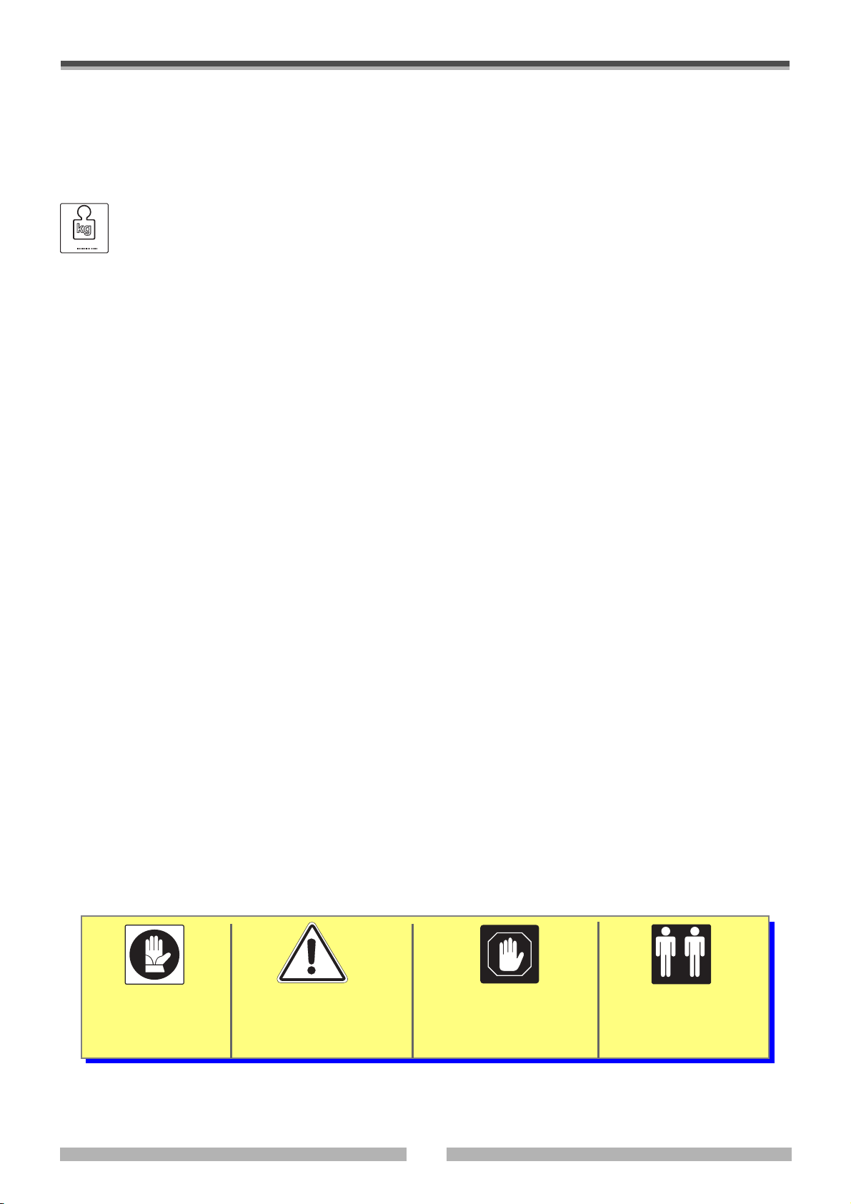
2.6 EXPLANATION OF SYMBOLS
• The symbols shown below may be found on the machine or in this instruction handbook.
• Pay attention to their meaning before going any further.
USE GLOVES
GENERAL DANGER
This symbol is always
accompanied by an
explanation of the danger
WARNING!
Important note
5
Operations that must be
carried out by at least
two people.
513005 POLAR

3 TECHNICAL SPECIFICATIONS
3.1 TECHNICAL DATA
Model
External dimensions (LxDxH) (mm)
Internal dimensions (LxDxH) (mm)
Useful volume (l)
Temperature range (°C)
Temperature variations
inside the space (1) (°C)
Temperature fluctuations
over time (1) (°C)
Supply voltage
Rated output (kW)
Absorbed current (A)
Thermal dissipation (kcal/h)
Refrigerant
Noise level (dB(A))
POLAR
110 H
730x960x1080
450x560x450
113
-40
-85
±3
±2
0,66
3
560
R404A/
MIXTURE
52
POLAR
110 SH
730x960x1080
450x560x450
113
-20
-45
±2
±1
0,33
1,5
280
R404A
52
POLAR
180 H
850x980x1080
570x700x450
180
-40
-85
±3
±2
230 V (+ 6 / - 10%) / 50 / 1 + G
0,66
3
560
R404A /
MIXTURE
52
POLAR
180 SH
850x980x1080
570x700x450
180
-20
-45
±2
±1
0,33
1,5
280
R404A
52
POLAR
370 H
1780x910x1020
1050x520x670
366
-40
-85
±3
±2
0,66
3
560
R404A /
MIXTURE
52
POLAR
370 SH
1780x910x1020
1050x520x670
366
-20
-45
±2
±1
0,33
1,5
280
R404A
52
Overall weight with
packaging (kg)
Model
External dimensions (LxDxH) (mm)
Internal dimensions (LxDxH) (mm)
Useful volume (l)
Temperature range (°C)
Temperature variations
inside the space (1) (°C)
Temperature fluctuations
over time (1) (°C)
Supply voltage
Rated output (kW)
Absorbed current (A)
Thermal dissipation (kcal/h)
220
POLAR
340 V
750x920x2000
450x530x1350
322
-40
-85
±3
±2
0,66
3
560
200
POLAR
340 SV
750x920x2000
450x530x1350
322
-20
-45
±2
±1
0,33
1,5
280
250
POLAR
530 V
1000x920x2000
700x530x1350
500
-40
-85
±3
±2
230 V (+ 6 / - 10%) / 50 / 1 + G
0,8
4,8
650
230
POLAR
530 SV
1000x920x2000
700x530x1350
500
-20
-45
±2
±1
0,33
1,5
280
280
POLAR
550 H
2320x910x1020
1590x520x670
550
-40
-85
±3
±2
0,66
3
560
260
POLAR
550 SH
2320x910x1020
1590x520x670
550
-20
-45
±2
±1
0,33
1,5
280
Refrigerant
Noise level (dB(A))
Overall weight with
packaging (kg)
R404A /
MIXTURE
52
260
R404A
52
240
R404A /
MIXTURE
55
290
R404A
55
270
R404A /
MIXTURE
55
390
R404A
55
370
(1) The values shown refer to tests carried out at a temperature of -40°C for the SH - SV models and of -80°C for the H –
V models.
513005 POLAR
6
3.2 FUSES
Model
POLAR 110 SH
POLAR 180 SH
POLAR 370 SH
POLAR 340 SV
POLAR 530 SV
POLAR 550 SH
POLAR 110 H
POLAR 180 H
POLAR 370 H
POLAR 340 V
POLAR 530 V
POLAR 550 H
Symbol Value Code
FU
FU
FU
FU
FU
FU
FU
FU
FU
FU
FU
FU
6 A
6 A
6 A
6 A
6 A
6 A
10 A
10 A
10 A
10 A
10 A
10 A
TT
TT
TT
TT
TT
TT
TT
TT
TT
TT
TT
TT
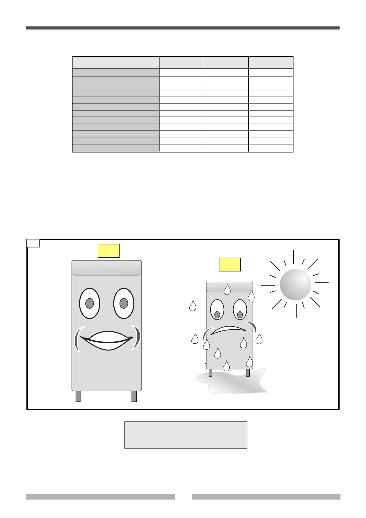
3.3 ENVIRONMENTAL CONDITIONS
In order for the appliance to operate correctly, it should be placed in a site with the following requisites:
•
far from heat sources,
•far from direct sunlight,
•far from air conditioning systems,
•in a dust-free ambient.
3.1
20°C
40°C
PO1207-130
PO1207-140
Ambient temperature min: +10°C
max + 30°C
Relative humidity UR max 80%
7
513005 POLAR
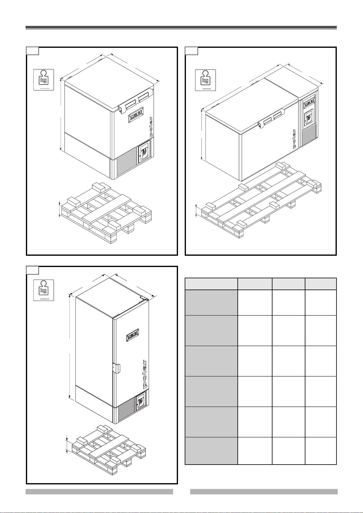
3.4 TECHNICAL LAY-OUT DIAGRAMS
3.33.2
Kg
PO1207-020
A
145
F
B
O
R
K
L
IF
T
T
R
U
C
K
S
ID
E
C
C
Kg
A
5
4
1
F
E
ID
S
T
E
L
L
A
P
S
N
A
R
T
O
R
K
L
IF
T
T
R
U
C
B
E
ID
S
T
E
L
L
A
P
S
N
A
R
T
K
S
ID
E
PO1207-030
3.4
Kg
PO1207-010
F
145
O
R
B
C
MODEL
A
BC
Polar 110 H
Polar 110 SH
1080
730
850
Polar 180 H
Polar 180 SH
1145
980
1145
A
Polar 370 H
Polar 370 SH
980
1780
800
Polar 340 V
Polar 340 SV
2000
730
850
Polar 530 V
Polar 530 SV
1985
980
850
Polar 550 H
K
L
IF
T
T
R
U
C
K
S
ID
E
A
P
S
N
A
R
T
E
ID
S
T
E
L
L
Polar 550 SH
1145
950
2315
513005 POLAR
8
4 HANDLING AND REMOVAL OF PACKAGING
4.1 PERSONNEL REQUISITES
Personnel in charge of handling the machine need no special requisites (just
remember the type of packaging).
However, we suggest that this is done by someone who is accustomed to using
machines for lifting and transport operations.
4.2 MACHINE CONDITIONS
The machine is normally supplied packed and on a pallet. If the machine is
delivered by our staff, it may be without packaging. Other types of packaging may
be supplied according to the destination and/or customer’s needs.
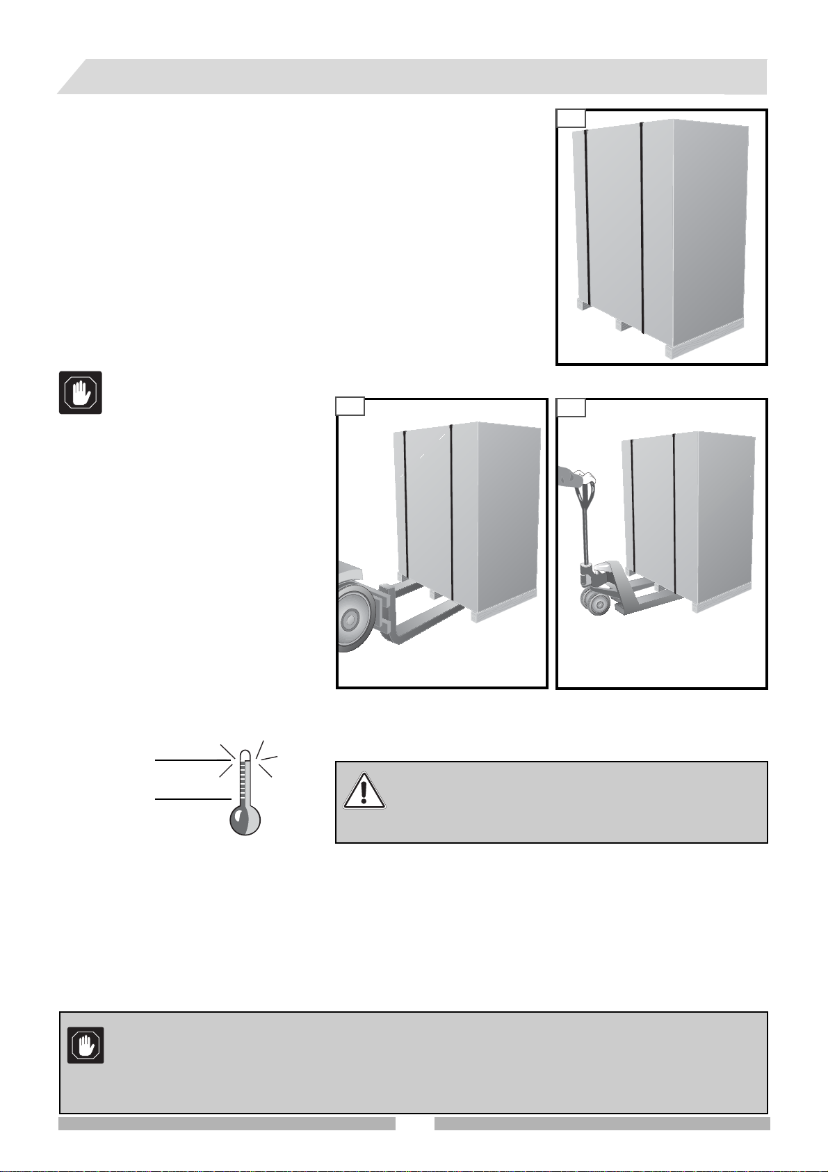
4.3 EQUIPMENT NEEDED FOR HANDLING
The machine can be raised and moved by a lift truck, bridge crane, crane or other
suitable means with an adequate capacity.
Check that the forks are level and
the load is stable before moving
the machine.
4.2
In order to handle the machine, the following rules should be observed:
• Move the machine slowly
• Do not tilt the machine, always keep it in
an upright position
•Always make sure you can control the
machine during handling
4.1
DS1710-010
4.3
Warning:
• Do not turn the machine upside-down
• Do not drag the machine
• Do not shake the machine
DS1710-050
How to store the machine
It should be kept in a dry environment with
an ambient temperature ranging from 0° ÷
40° C.
Do not place packaged machines one on top of the other and always keep
them in an upright position as indicated by the special arrows marked on
the packaging itself.
40° C
Make sure that the forks do not hit the machine frame.
0°C
HOW TO USE A LIFT TRUCK TO RAISE AND TRANSPORT PALLETIZED MACHINE
Take care to position the lift truck forks correctly so as not to damage the machine. The person in charge of handling
will be responsible for avoiding damage to the external structure during this operation.
HOW TO RAISE AND MOVE WITH A BRIDGE CRANE
Accessories: textile fibre belts and PVC angle bars.
Weight: see technical specifications
If it is hit accidentally, check immediately for any damage
and if necessary, contact the manufacturer.
DS1710-060
Do not use place the machine in a sling of metal cables or chains as these could damage it.
Never put a sling around a machine without its pallet.
In order to prevent the oil in the compressor from flowing into the refrigerating circuit, only transport, stock
and handle the equipment in an upright position according to the instructions on the packaging. If the
machine is placed on its side, leave it in an upright position for at least 24 hours before switching on.
9
513005 POLAR
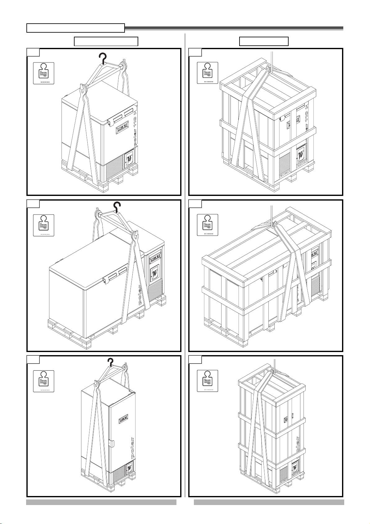
Diagram of slings
4.4 4.5
With packagingWithout packaging
Kg
PO1207-050
4.6 4.7
Kg
Kg
PO1207-090
Kg
PO1207-060
4.8 4.9
Kg
PO1207-070
513005 POLAR
10
PO1207-100
Kg
PO1207-110
MANUAL HANDLING
The machine is equipped with four wheels so that it can be moved manually.
If the floor of the installation site is flat, no special precautions are required.
Take all the necessary precautions, however, before moving the machine:
• Bear in mind the mass which has to be moved and calculate the number of people needed to control the mass during
movement.
• check that the floor is smooth and completely flat.
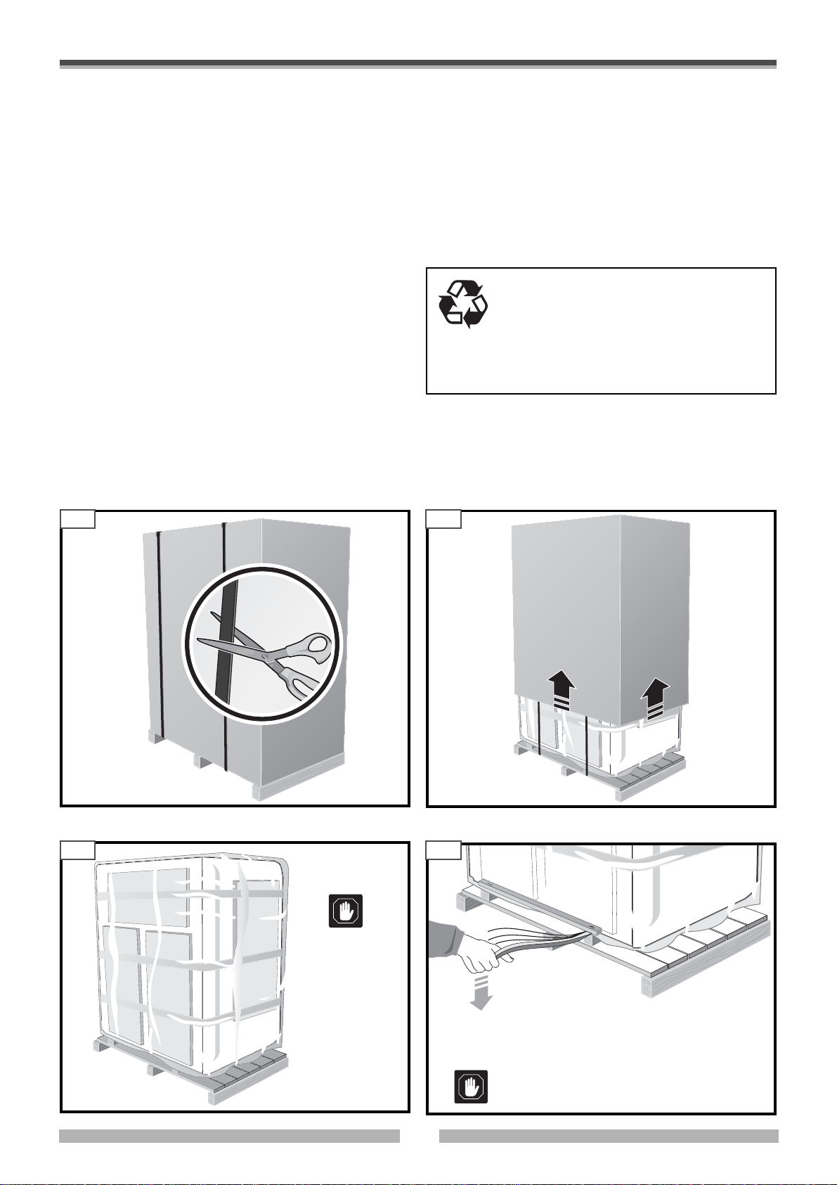
4.4 REMOVAL OF PACKAGING
The machine is delivered ready-to-go.
Before removing the machine from its packaging, check
that it has not been damaged during transport.
If so:
a) Contact your area representative
b) Make a written report and if possible attach photographs
All the packaging materials can be recycled
and can be disposed of according to the
regulations in force. Take care to eliminate
the packaging so that it does not become a
danger and throw away the plastic bags, as
they could cause children to suffocate.
showing the damage
c) Send a copy of the report to:
• Remove all the packaging and destroy according to the
Shipping agent insurance company
Shipping agent
Manufacturer or area representative
laws in force.
•Eliminate the parts with nails and eliminate plastic bags
and plastic sheeting.
4.4.1 How to remove the outer straps 4.4.2 How to remove the cardboard casing
4.10 4.11
DS1710-040
DS1710-010
4.4.3 Removal of plastic materials
4.4.4 How to remove the wooden side blocks
4.12 4.13
When removing
the plastic materials, make sure
that you don’t
scratch the surface of the appliance.
DS1710-090
• Remove the screws that block the ledges on the
•
DS1710-030
DS1710-070
cabinet.
Use a special lever to remove the two wooden blocks.
Take care not to scratch the surface of the
machine.
11
513005 POLAR
 Loading...