

Angelantoni Industrie 110 H, 110 SH, 370 SH, 550 SH, 370 H Service manual [en, it]
...
CONGELATORI/ FREEZERS
PLATINUM
110 SH
110 H
370 SH
370 H
550 SH
550 H
340 SV
340 SV Plus
340 V
340 V Plus
500 Sv
500 SV Plus
500 V
500 SV Plus
750 V Vip
750 V Vip Plus
750 SV Vip
750 SV Vip Plus
iso 9001:2000
nato aqap110
PL1810-F01
iso 14001
Manuale di installazione, uso e manutenzione
Installation, use and maintenance handbook
Angelantoni Industrie S.p.A.
06056 Massa Martana (Pg) Italy
Tel. (++39) 075.8955.1 (a.r.)
Fax (++39) 075.8955200
Internet: www.angelantoni.it
E-Mail:info@angelantoni.it
Cod. 514903 - Rel. 021105

464 Località Cimacolle
06056 Massa Martana (Pg) Italy
AVVERTENZA IMPORTANTE
I prodotti realizzati dal costruttore sono caratterizzati da un elevato contenuto tecnologico che talvolta richiede
un adattamento tecnico di parti o componenti altrimenti reperibili sul mercato nella loro versione standard
commerciale. Pertanto, la sostituzione di parti o componenti con altri non originali, ossia non forniti e garantiti
direttamente dal COSTRUTTORE, nonché l’accertamento di interventi tecnici effettuati da personale non autorizzato,
comporteranno l’immediata cessazione della garanzia, se in essere, e comunque di qualsiasi responsabilità nei
confronti dell’acquirente e di terzi, da parte del COSTRUTTORE stesso.
IMPORTANT WARNING
The high level of technology of the products made by the manufacturer occasionally requires components to be
adapted from parts normally found on the market in their standard commercial version. Therefore, if it should be
ascertained that any parts have been replaced with other components that are not original, i.e. that have not
been supplied and guaranteed directly by the MANUFACTURER, or that any unauthorised technical interventions
have been carried out, the guarantee, if any is in force, shall be considered no longer valid and the MANUFACTURER
himself shall no longer be held responsible towards the purchaser and towards third parties.
AVVERTISSEMENT IMPORTANT
Les produits réalisés par le constructeur sont caractérisés par un haut niveau technologique qui demande par fois
une adaptation technique de parties ou de composants autrement disponibles sur le marché dans leur version
commerciale standard. Pour cette raison, la substitution de parties ou composants par d’autres non originaux,
c’est à dire non fournis et garantis directement par le CONSTRUCTEUR, ou bien la constatation que du personnel
non autorisé a effectué des interventions techniques; auront pour conséquence l’immédiate cessation de la garantie
en cours et de toute façon de toutes responsabilités du CONSTRUCTEUR vis à vis de l’acheteur ou de tierces
parties.
WICHTIGE WARNUNG
Das hohe technische Niveau der Produkte des Herstellers erfordert teilweise Komponenten, die verändert
werden müssen gegenüber handelsüblichen Produkten ; wie sie am Markt zu finden sind.
Beim Austausch von Teilen oder Komponenten; die nicht dem Orginal entsprechen, das heißt nicht direkt vom
HERSTELLER geliefert und garantiert wurden, bzw. daß technische Veränderungen durch nicht autorisiertes
Personal vorgenommen wurde, gilt die Garantie, falls noch in Kraft, als erloschen und der HERSTELLER kann
nicht mehr länger haftbar gemacht werden gegenüber dem Käufer und Dritten.
AVISO IMPORTANTE
Los productos elaborados por el fabricante se caracterizan por un alto nivel tecnológico y ocasionalmente
requieren adaptaciones técnicas de partes o componentes que normalmente se encuentran en el mercado en
su versión comercial estándar.
Por tanto, la sustitución de partes o componentes, por otros que no sean originales, es decir no suministrados
y garantizados por el FABRICANTE, o bien se constata la intervención técnica por de personal no autorizado,
supondrá el cese inmediato de la garantía, si está en vigor, así como de cualquier otra responsabilidad del
FABRICANTE de cara tanto al comprador como a terceras personas.

SOMMARIO SUMMARY
1RIEPILOGO DEI DATI DI MARCATURA .....................................2
2AVVERTENZE..............................................................................3
3 CARA TTERISTICHE TECNICHE .................................................6
4MOVIMENTAZIONE E DISIMBALLO .......................................... 10
5 DESCRIZIONE DEL SISTEMA ................................................... 14
6 INSTALLAZIONE ........................................................................20
7U
8AVVIAMENTO ............................................................................. 26
9 USO ...................................................................................33
10 ORGANI DI SICUREZZA-VERIFICA E TARATURA ................... 38
11 MANUTENZIONE ........................................................................ 39
12 INCONVENIENTI E RIMEDI........................................................ 41
13 DISINSTALLAZIONE .................................................................. 43
14 SCHEMI ...................................................................................44
VVERTENZE GENERALI............................................................... 3
2.1 A
2.2 A
VVERTENZE PER IL TRASPORTO E LA MOVIMENTAZIONE
2.3 AVVERTENZE PER L’INSTALLAZIONE ............................................... 4
2.4 AVVERTENZE PER IL PERSONALE ADDETTO .....................................4
VVERTENZE PER LA MANUTENZIONE .............................................5
2.5 A
2.6 S
PIEGAZIONE DEI SIMBOLI ............................................................ 5
ATI TECNICI ............................................................................. 6
3.1 D
3.2 F
USIBILI ...................................................................................8
3.3 CONDIZIONI AMBIENTALI ..............................................................8
ISEGNI TECNICI DI LAY-OUT .........................................................9
3.4 D
4.1 R
EQUISITI DEL PERSONALE .........................................................10
4.2 S
TATO DELLA MACCHINA............................................................. 10
EZZI NECESSARI PER LA MOVIMENTAZIONE ................................... 10
4.3 M
4.4 S
OLLEVAMENTO E MOVIMENTAZIONE CON CARROPONTE
............................ 4
........................... 11
4.5 DISIMBALLO ....................................................................... 11
IMOZIONE REGGETTE ESTERNE ........................................12
4.5.1 R
4.5.2 ESTRAZIONE CAPPELLO IN CARTONE................................... 12
4.5.3 R
IMOZIONE PLASTICA ...................................................... 12
IMOZIONE BLOCCHI IN LEGNO LATERALI ............................. 12
4.5.4 R
4.5.5 RIMOZIONE PALLET.......................................................... 13
4.6 I
MMOBILIZAZIONE DELLA MACCHINA ..............................................13
ISTA GENERALE ......................................................................14
5.1 V
ISTA INTERNA ......................................................................... 15
5.2 V
5.3 D
ESCRIZIONE DELLE CONNESSIONI ESTERNE................................... 16
5.4 SISTEMA DI CONTROLLO ............................................................. 17
ISTEMA "BIOGUARD" ...............................................................18
5.5 S
5.6 S
ISTEMA REFRIGERANTE ............................................................ 18
5.7 F
UNZIONAMENTO DEL CIRCUITO DI RAFFREDDAMENTO
.......................... 18
5.8 VOLTAGE BOOSTER (OPZIONALE) .................................................19
5.9 F
UNZIONAMENTO DEL CIRCUITO DI RAFFREDDAMENTO
CO2 (OPZIONALE) ..........................................................................19
AUSILIARIO A LN2/ ..
5.10ISOLAMENTO ............................................................................19
6.1 P
OSA DELLA MACCHINA .............................................................20
OSTITUZIONE BOMBOLA ..................................................21
6.1.1 S
OLLEGAMENTO ELETTRICO ........................................................ 22
6.2 C
6.2.1 COLLEGAMENTO ELETTRICO ALLA RETE ..............................22
6.2.2 S
OSTITUZIONE DEL CAVO DI ALIMENTAZIONE
6.2.3 COLLEGAMENTO ALLARME REMOTO .................................... 23
6.2.4 INTERFACCIA SERIALE (OPZIONALE) ....................................24
SO PREVISTO DAL FABBRICANTE ........................................................ 25
COPO DELLE MACCHINE ............................................................ 25
7.1 S
7.2 DESTINAZIONE DELLE MACCHINE .................................................. 25
PERATORE ............................................................................. 25
7.3 O
IMITAZIONI D’USO ....................................................................25
7.4 L
7.5 RISCHI RESIDUI .........................................................................25
ESCRIZIONE DEL PANNELLO COMANDI..........................................26
8.1 D
8.2 MESSA IN FUNZIONE ..................................................................28
MPOSTAZIONE DELLA TEMPERATURA DI ESRCIZIO ............................ 28
8.3 I
MPOSTAZIONE DELLA TEMPERATURA DI SET DEGLI ALLARMI .............. 29
8.4 I
8.5 ATTIVAZIONE/DISATTIVAZIONE SISTEMA BIOUGUARD E BLOCCO/SBLOCCO
PANNELLO
8.6 MEMORIZZAZIONE CARTA (TAG) - (SOLO MOD. CON DISPOSITIVO BIOGUARD)31
8.7 APERTURA/CHIUSURA PORTA .......................................................32
8.7.1D
8.7.2 D
BIOGUARD .......................................................................32
9.1 INSTALLAZIONE DEI CASSETTI (OPZIONALE) - SOLO MODELLI VERTICALI 33
9.2 I
COMANDI (SOLO MODELLI DOTATI DI QUESTO DISPOSITIVO)..30
ESCRIZIONE APERTURA / CHIUSURA PORTA CON CHIAVE.......... 32
ESCRIZIONE APERTURA / CHIUSURA PORTA CON SISTEMA
NSTALLAZIONE DEI RIPIANI
-
SOLO MODELLI VERTICALI
.......................... 23
........................ 34
9.3 CARICAMENTO DEI PRODOTTI.......................................................34
9.4 R
EGISTRATORE GRAFICO DI TEMPERATURA (OPZIONALE
9.4.1USO DEL REGISTRATORE .................................................... 35
9.5 S
CARICAMENTO DA TI TRAMITE PORTA SERIALE (OPZIONALE) .............. 37
ONDA AGGIUNTIVA (OPZIONALE) .................................................37
9.6 S
9.7 FORO PASSANTE (OPZIONALE) ..................................................... 37
9.8 C
ONDENSAZIONE AD ACQUA (OPZIONALE) ...................................... 37
ONTENITORI DI STOCCAGGIO ......................................................38
9.9 C
11.1SBRINAMENTO, PULIZIA DELLA STRUTTURA E DELLE PORTE ............... 39
11.2PULIZIA DEL CONDENSATORE AD ARIA ........................................... 40
ULIZIA DEL CONDENSATORE AD ACQUA ........................................40
11.3P
11.4 M
ANUTENZIONE DEL SISTEMA DI RAFFREDDAMENTO
11.5 M
ANUTENZIONE PARTE ELETTRICA-ELETTRONICA
ESSA FUORI SERVIZIO .............................................................. 43
13.1M
13.2R
OTTAMAZIONE......................................................................... 43
CHEMA FRIGORIFERO (-40°C)................................................... 44
14.1S
14.2S
CHEMA FRIGORIFERO (-80°C)................................................... 45
CHEMA ELETTRICO (-40°C)......................................................46
14.3S
14.4SCHEMA ELETTRICO (-85°C)......................................................48
14.5S
CHEMA ELETTRICO (APPARECCHIATURE A -85°C CON BOOSTER) .....50
)........................... 34
................................. 40
..................................... 40
1 SUMMARY OF RATING PLKATE DATA......................................2
2WARNINGS .................................................................................. 3
3 TECHNICAL SPECIFICATIONS ..................................................7
4 HANDLING AND REMOVAL OF PACKAGING .......................... 10
5 DESCRIPTION OF THE SYSTEM............................................... 14
ENERAL WARNINGS .................................................................. 3
2.1 G
ARNINGS FOR TRANSPORT AND HANDLING .................................... 4
2.2 W
2.3 W
ARNINGS FOR INSTALLATION ...................................................... 4
2.4 WARNINGS FOR PERSONNEL IN CHARGE OF THE MACHINE .................. 4
ARNINGS FOR MAINTENANCE ..................................................... 5
2.5 W
2.6 E
XPLANATION OF SYMBOLS .......................................................... 5
ECHNICAL DATA........................................................................ 7
3.1 T
3.2 F
USES ....................................................................................8
3.3 ENVIROMENTAL CONDITIONS ......................................................... 8
ECHNICAL LAY-OUT DIAGRAMS ....................................................9
3.4 T
4.1 P
ERSONNEL REQUISITES ............................................................. 10
4.2 M
ACHINE CONDITIONS ................................................................ 10
QUIPMENT NEEDED FOR HANDLING .............................................. 10
4.3 E
4.4 HOW TO RAISE AND MOVE WITH A BRIDGE CRANE ........................... 11
4.5 R
EMOVAL OF PACKAGING ........................................................... 11
OW TO REMOVE THE OUTER STRAPS.................................. 12
4.5.1 H
4.5.2 HOW TO REMOVE THE CARDBOARD CASING ..........................12
4.5.3 R
EMOVAL OF PLASTIC MATERIALS ......................................12
OW TO REMOVE THE WOODEN SIDE BLOCKS ........................12
4.5.4 H
4.5.5 HOW TO REMOVE THE PALLET ............................................13
4.6 H
OW TO BLOCK THE MACHINE ...................................................... 13
ENERAL VIEW .........................................................................14
5.1 G
NTERNAL VIEW ......................................................................... 15
5.2 I
5.3 D
ESCRIPTION OF EXTERNAL CONNECTIOONS ................................... 16
5.4 CONTROL SYSTEM .....................................................................17
IOGUARD” SYSTEM ................................................................18
5.5 “B
5.6 C
OOLING SYSTEM ..................................................................... 18
5.7 FUNCTIONING OF THE COOLING SYSTEM......................................... 18
5.8 V
OLTAGE BOOSTER (OPTIONAL) ................................................... 19
5.9 F
UNCTIONING OF THE AUXILIARY
5.10INSULATION .............................................................................. 19
LN2/CO2
COOLING SYSTEM (OPTIONAL
)19
6 INSTALLATION ........................................................................... 20
6.1 POSITIONING OF THE MACHINE .....................................................20
6.1.1 HOW TO REPLACE THE CYLINDER........................................ 21
LECTRICAL VIRING ................................................................... 22
6.2 E
7 USE FORESEEN BY THE MANUFACTURER ............................ 25
7.1 A
7.2 I
7.3 OPERATOR............................................................................... 25
7.4 U
7.5 U
8START-UP ................................................................................... 26
8.1 D
8.2 S
8.3 SETTING THE OPERATING TEMPERATURE ........................................28
8.4 S
8.5 A
8.6 CARD MEMORISATION (TAG) - (BIOGUARD MODELS ONLY).................. 31
8.7 HOW TO OPEN/ CLOSE THE DOOR ................................................. 32
OW TO CONNECT TO THE ELECTRICAL MAINS SUPPLY ............ 22
6.2.1 H
6.2.2 REPLACEMENT OF THE SUPPLY CABLE................................. 23
EMOTE ALARM CONNECTION............................................ 23
6.2.3 R
ERIAL INTERFACE (OPTIONAL) .......................................... 24
6.2.4 S
IM OF THE MACHINES ...............................................................25
NTENDED USE OF THE MACHINES .................................................25
SE LIMITS ..............................................................................25
SE OF PROTECTIVE CLOTHINGS .................................................. 25
ESCRIPTION OF THE CONTROL PANEL ..........................................26
TART-UP ................................................................................28
ETTING THE ALARM TEMPERATURE SET POINT ............................... 29
CTIVATION/DEACTIVATION OF THE BIOGUARD SYSTEM AND LOCKING
UNLOCKING THE CONTROL PANEL
) ....................................................................................... 30
DEVICE
8.7.1 D
ESCRIPTION OF HOW TO OPEN/CLOSE THE DOOR WITH A KEY 32
ESCRIPTION OF HOW TO OPEN/CLOSE THE DOOR WITH THE
8.7.2 D
BIOGUARD SYSTEM .......................................................... 32
(O
NLY FOR MODELS EQUIPED WITH THIS
/
9 USE ...................................................................................33
9.1 HOW TO INSTALL THE DRAWERS (OPTIONAL) - VERTICAL MODELS ONLY 33
9.2 HOW TO INSTALL THE SHELVES- VERTICAL MODELS ONLY ...................34
9.3 P
RODUCT LOADING.................................................................... 34
EMPERATURE CHART RECORDER (OPTIONAL) ................................ 34
9.4 T
9.4.1 USE OF THE RECORDER ...................................................35
9.5 D
ATA DOWNLOADING VIA SERIAL PORT (OPTIONAL) .......................... 37
DDITIONAL PROBE (OPTIONAL)................................................... 37
9.6 A
9.7 PORT HOLE (OPTIONAL) .............................................................37
9.8 W
ATER CONDENSER CONNECTION (OPTIONAL)................................ 37
TORAGE CONTAINERS ...............................................................38
9.9 S
10 SAFETY DEVICES- CHECK AND SET-UP ................................38
11 MAINTENANCE ..........................................................................39
11.1HOW TO DEFROST AND CLEAN THE MAIN BODY AND DOORS ..............39
11.2CLEANING OF THE AIR CONDENSER...............................................40
LEANING OF THE WATER CONDENSER ..........................................40
11.3C
11.4C
OOLING SYSTEM MAINTENANCE ..................................................40
11.5
MAINTENANCE
OF
THE ELECTRICAL-ELECTRONIC PART
........................ 40
12 TROUBLESHOOTING................................................................. 41
13 REMOVAL FROM INSTALLATION SITE ....................................43
13.1D
ISASSEMBLY ........................................................................... 43
13.2S
14 DIAGRAMS.................................................................................. 44
CRAPPING .............................................................................. 43
EFRIGERATOR DRAWING (-40°C)...............................................44
14.1R
14.2R
EFRIGERATOR DRAWING (-80°C)...............................................45
LECTRIC DIAGRAM (-40°C) ......................................................46
14.3E
14.4ELECTRIC DIAGRAM (-85°C) ......................................................48
14.5E
LECTRIC DIAGRAM (EQUIPMENT AT -85°C WITH BOOSTER).............. 50
1
514903
2
1
Model
Serial No
°C RH% IP
POWER
SUPPLY
REFRIGERANT
PROPERTIES
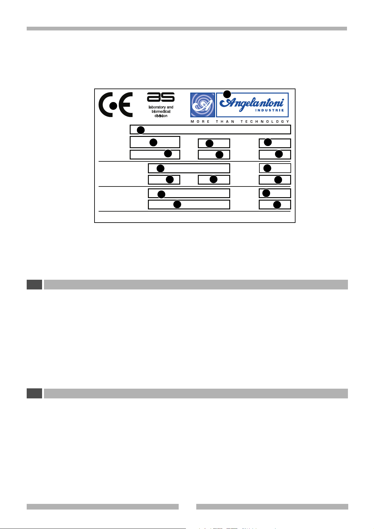
1 RIEPILOGO DEI DATI DI MARCATURA
I
3
4
V~
10
P Kw A Class
n. 1
15
n. 2
COUNTRY OF ORIGIN: ITALY
Year
6
11
16
5
Weight kg
7
Hz
12
Pmax kPa
Pmax kPa
8
9
13
14
17
18
• Localizzate la targa apposta alla macchina per rilevare i dati tecnici.
•Verificate il modello della macchina e la tensione di alimentazione prima di compiere qualsiasi operazione.
• Se rilevate delle discordanze contattate subito il produttore o l'azienda che ha effettuato la fornitura.
1 Marchio di conformità CE
2 Marchio e indirizzo del fabbricante
3 Modello
4 Numero di serie
5 Anno di costruzione
6 Temperatura
7 Umidità relativa
8 Peso
1 SUMMARY OF RATING PLATE DATA
GB
9 Grado di protezione elettrica
10 Tensione di alimentazione
11 Potenza assorbita
12 Assorbimento elettrico
13 Frequenza
14 Classe di isolamento
15-16 Tipo di refrigerante
17-18 Pressione refrigerante
• Find the special rating plate on the machine in order to check the technical data.
• Check the machine model and supply voltage before carrying out any operation whatsoever.
• If you find any discrepancies, contact the manufacturer or your supplier immediately.
1 EC compliancy mark
2 Manufacturer’s address
3 Model
4 Serial N°
5 Year of manufacture
6 Temperature
7 Relative humidity
8Weight
9 Electrical protection grade
10 Supply voltage
11 Absorbed power
12 Electrical absorption
13 Frequency
14 Isolation class
15-16 Type of refrigerant
17-18 Pressure of refrigerant
514903
2

2AVVERTENZE
I
2.1 AVVERTENZE GENERALI
• Non effettuate operazioni o manovre se non siete assolutamente certi del loro effetto; in caso di dubbio contattate il servizio di assistenza tecnico più vicino o direttamente il produttore.
• Il produttore si ritiene sollevato da ogni responsabilità per danni
causati alla macchina o alle cose nei casi seguenti:
- uso improprio della macchina
- impiego di personale non idoneo
- montaggio e installazione non corretti
- difetti negli impianti
- modifiche o interventi non autorizzati alla macchina
- utilizzo di parti di ricambio non originali
- inosservanza delle norme dettate nel presente manuale
-eventi eccezionali
• Il presente manuale di istruzioni si rivolge ai seguenti soggetti:
- Addetti del trasporto, movimentazione e disimballo
- Addetti alla preparazione degli impianti e del sito di installazione
- Installatori
- Addetti all'uso della macchina
- Addetti alla manutenzione
• Il manuale di istruzioni indica l'utilizzo previsto dal f ab bricante e non può mai sostituire un’adeguata esperienza dell’operatore, può costituire solo un promemoria delle principali operazioni da svolgere.
• Il manuale di istruzioni deve essere conservato con la massima cura e reso sempre disponibile per la consultazione. Se
necessario fotocopiate le pagine che destinerete all'uso diretto sulla macchina. Il manuale de ve a vere una dur ata alme-
no pari a quella della macchina.
• Il manuale di istruzioni rispecchia la tecnica al momento della
costruzione della macchina; il produttore si riserva il diritto di
apportare tutte le modifiche ritenute opportune, alle macchine e ai manuali di istruzione, senza obbligo di preavviso o di
sostituzione.
In caso di smarrimento o distruzione del manuale è possibile
richiederne una copia apponendo, nella richiesta, i dati di
marcatura (vedi cap1).
La presente macchina non è contemplata nell’allegato IV
delle normative comunitarie sulle macchine, pertanto è
applicata la procedura di cui all’articolo 8, paragrafo 2,
lettera A, delle normative comunitarie sulle macchine 89/
392/CEE e 91/368/CEE. L’articolo 8, paragrafo 2, lettera A
delle normative comunitarie sulle macchine 89/392/CEE e
91/368/CEE obbliga il costruttore a realizzare il fascicolo
previsto dall’allegato delle sopracitate leggi, realizzato e
conservato nell’archivio tecnico della ditta Angelantoni
Industrie spa località Cimacolle Massa Martana Perugia.
2 WARNINGS
GB
2.1 GENERAL WARNINGS
• Do not carry out any operations or manoeuvres unless you
are absolutely certain of their effect; if in doubt, contact your
nearest technical assistance service or the manufacturer
himself.
• The manufacturer will not be held responsible f or damage to
the machine or to objects in the following cases:
- improper use of the machine
- use of unsuitable personnel
- incorrect assembly and installation
- defects in the plant systems
- unauthorized modifications or operations to the machine
- use of spare parts that are not original pieces
-failure to comply with the norms given in this handbook
-exceptional events
• This instruction handbook has been designed for the following
personnel:
-Personnel in charge of transport, handling and removal
of packaging
-Personnel in charge of the preparation of the plant
systems and installation site
- Installers
-Personnel in charge of using the machine
-Personnel in charge of maintenance
• The instruction handbook indicates the use foreseen by the
manufacturer and cannot ever replace adequate experience
of the operator. It can only be used as a reminder of the main
operations to be carried out.
• The instruction handbook should be kept carefully and should
also be within easy reach for reference. If necessary,
photocopy the pages concerned directly with machine use.
The handbook should last at least the life-time of the machine
itself.
• The instruction handbook gives technical information on how
the machine is manufactured at the present time; the
manufacturer reserves the right to carry out any modifications
he deems necessary to the machines and to the instruction
handbooks, without prior notice or replacement.
If you lose or destroy the handbook, y ou may ask for a cop y.
Please give the rating plate data (see chap. 1) in y our request.
This machine is not referred to in enclosure IV of the
community norm on machines, and therefore the procedure in article 8, paragraph 2, letter A in the Community
norms for machines 89/392/CEE and 91/368/EEC has been
applied. Article 8, paragraph 2, letter A of the Community
norms for machines 89/392/CEE and 91/368/EEC obliges
the manufacturer to provide the file foreseen by the
enclosure of the afore-mentioned laws, and to store it in
the technical archives of the company Angelantoni Industrie spa, località Cimacolle, Massa Martana, Perugia.
3
514903

2AVVERTENZE
I
2.2 AVVERTENZE PER IL TRASPORTO E LA MOVIMENTAZIONE
• Questo simbolo, apposto su ciascun imballo indica il peso di ogni collo. Occorre sempre verificare che gli attrezzi e le
macchine atte alla movimentazione e trasporto siano adeguate.
• Mantenete sempre la macchina in posizione verticale. Se accidentalmente la macchina è stata capovolta o coricata
non avviatela ma ponetela in posizione corretta e contattate il produttore.
2.3 AVVERTENZE PER L'INSTALLAZIONE
• L'installazione deve essere effettuata da personale specializzato.
• Occorre eseguire scrupolosamente le procedure per la realizzazione degli impianti prima di installare la macchina.
• In fase di predisposizione del sito di installazione tenete conto dello spazio e delle condizioni di lav oro del personale addetto in
modo da ridurre al massimo la rumorosità, l'affaticamento, il disagio e quant'altro possa influire negativamente sulle persone.
• Nel prevedere il luogo di installazione tenete conto di lasciare sufficiente spazio per il controllo, la manutenzione, la pulizia e
l'asporto dei residui di materiale scarto di lavorazione.
• Provvedete ad illuminare adeguatamente il posto di lavoro in modo che il personale addetto si trovi nelle migliori condizioni
operative.
• Nel definire il punto di installazione riferitevi alle normative vigenti e in particolare:
- attuate tutti i dispositivi antincendio e di sicurezza.
2.4 AVVERTENZE PER IL PERSONALE ADDETTO
• La macchina può essere utilizzata solo da parte di personale che abbia preso completa visione delle norme descritte nel
presente manuale.
•L’apertura della camera a temperature molto diverse da quelle ambientali può causare inconvenienti:se la temper atura interna
è molto bassa possono generarsi fenomeni di condensa e brinatura a causa dell’umidità ambiente.
Frequenti aperture della porta in queste condizioni potranno generare ostruzione degli scambiatori termici.
2 WARNINGS
GB
2.2WARNINGS FOR TRANSPORT AND HANDLING
• This symbol, placed on each packaging, indicates the weight of each package .
Always check that the tools and machines to handle and transport the machine are adequate.
• Always k eep the machine in an upright position. If the machine should accidentally turn upside-down or on its side, do
not switch it on. Put it in the correct position and contact the manufacturer.
2.3 WARNINGS FOR INSTALLATION
• Installation should always be carried out by specialized personnel.
• Carefully follow the instructions on how to prepare the plant systems before installing the machine.
• When the installation site is being prepared, bear in mind the space and work conditions of the personnel in charge of the
machine so as to reduce to a minimum noise, fatigue , discomfort and anything else which may ha v e a negative influence on the
staff.
• When designing the installation site, remember to leave sufficient space for control, maintenance, cleaning, and removal of
production waste material.
• Make sure that the work site is adequately lit so that personnel can work in optimum conditions.
• When designing the installation site, please refer to the norms in force and in particular:
- set up all the firefighting and safety devices.
2.4 WARNINGS FOR PERSONNEL IN CHARGE OF THE MACHINE
• The machine may only be used by personnel who have read the rules described in this handbook.
•To open the chamber when its temperature is very different from the ambient temperature could cause problems: if the internal
temperature is very low , condensate and frosting could be caused b y ambient humidity. If the door is often opened under these
conditions, the heat exchangers could be obstructed.
514903
4
2AVVERTENZE
I
2.5 AVVERTENZE PER LA MANUTENZIONE
• Scollegate sempre la macchina dalla rete elettrica prima di
effettuare qualsiasi operazione di manutenzione.
•Per la pulizia delle parti verniciate non utilizzate solventi o
alcool in quanto tali prodotti possono danneggiare le superfici.
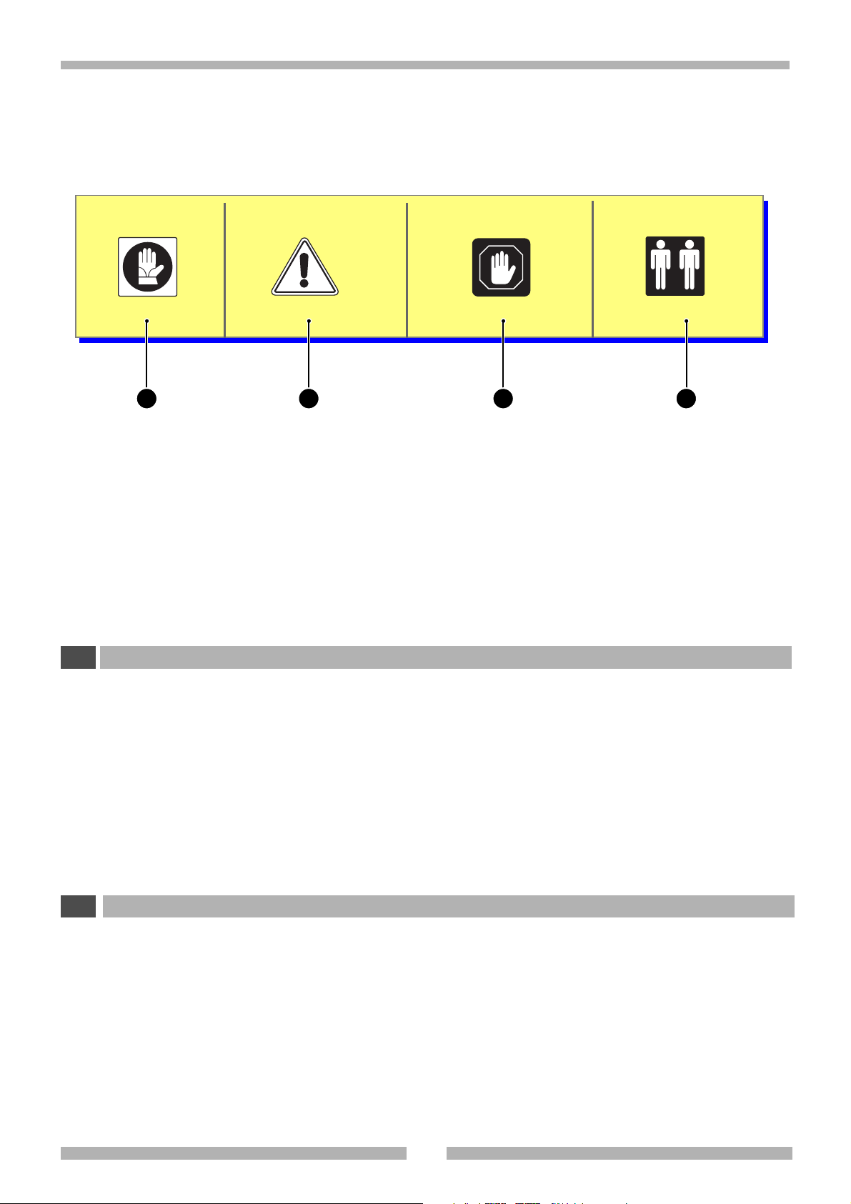
2.6 SPIEGAZIONE DEI SIMBOLI
•I simboli mostrati possono trovarsi sulla macchina o all'interno del presente manuale di istruzioni.
•Ponete attenzione al loro significato prima di procedere.
3 41 2
1 Uso di guanti
2 PERICOLO GENERICO
Questo simbolo è sempre accompagnato
dalla spiegazione del pericolo
3 ATTENZIONE!
Nota importante
4 Operazioni che devono essere compiute
da almeno due persone.
2 WARNINGS
GB
2.5 WARNINGS FOR MAINTENANCE
• Always disconnect the machine from the electrical mains
before carrying out any maintenance operation.
• Do not use solvents or alcohol to clean the varnished parts
as these products could damage the surface.
2.6 EXPLANATION OF SYMBOLS
• The symbols shown below may be found on the machine or
in this instruction handbook.
•Pay attention to their meaning before going any further.
1 Use gloves
2 GENERAL DANGER
This symbol is always accompanied by an
explanation of the danger
3 WARNING
Important nore
4 Operations that must be carried out by
at least two people
5
514903
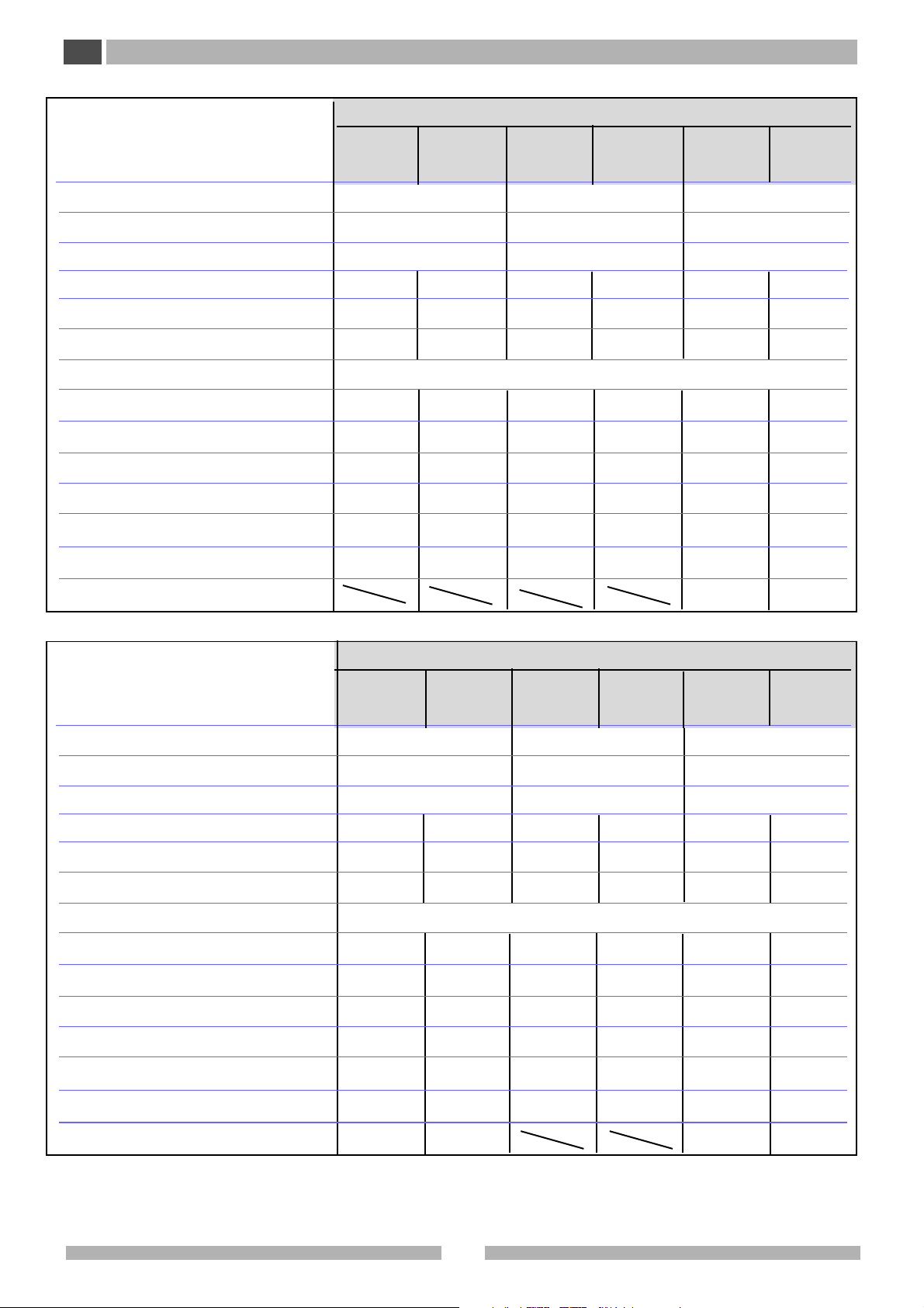
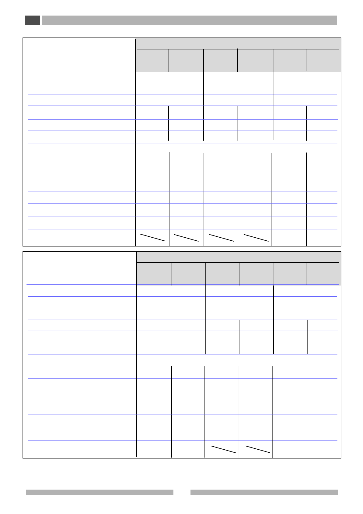
3 CARA TTERISTICHE TECNICHE
I
3.1 DATI TECNICI
PLATINUM
Modello
Dimensioni esterne (LxPxH) (mm)
Dimensioni interne (LxPxH) (mm)
Volume utile (l)
Campo di temperatura (°C)
Variazione temperatura nello spazio(
Fluttuazione temperatura nel tempo(1) (°C)
Tensione d'alimentazione
Corrente massima assorbita (A)
Dissipazione termica (kcal/h)
Consumo energetico (kW/24h)
Gas refrigerante
Grado di rumorosità (
2
) (dB(A))
Peso complessivo con imballo (kg)
1
) (°C)
110 H 110 SH 370 H 370 SH
730 x 850 x 1080
450 x 560 x 450
113
-40 / -85
±1,5
±3,5
7
450
12,4
R404A/ R508 o
mixture
(3)
52
220
-20 / -45
±1
±3
230V (+6 / -10%) / 50 (60) Hz
3,5
180
5
R404A
52
200
1780 x 855 x 1140
1050 x 520 x 670
366
-40 / -85
±2
±3
7
450
12,4
R404A/ R508 o
mixture
(3)
52
280
-20 / -45
R404A
±1
±2
3,5
180
5
52
260
340 V plus
-40 / -85
(3)
/ 1 +T
R404A/ R508 o
340 V
340 SV plus
765 x 900 x 1985
450 x 530 x 1350
322
-20 / -45
±2
±3
7
580
16,2
mixture
(3)
R404A
52
260
340 SV
±1
±2
3,5
230
6,5
52
260
Carico massimo su ogni ripiano (kg)
Modello
Dimensioni esterne (LxPxH) (mm)
Dimensioni interne (LxPxH) (mm)
Volume utile (l)
Campo di temperatura (°C)
Variazione temperatura nello spazio(
Fluttuazione temperatura nel tempo(1) (°C)
Tensione d'alimentazione
Corrente massima assorbita (A)
Dissipazione termica (kcal/h)
Consumo energetico (kW/24h)
Gas refrigerante
Grado di rumorosità (
2
) (dB(A))
1
) (°C)
500V
500 V plus
1015 x 900 x 1985
700 x 530 x 1350
500
-40 / -85
±2
±3
9
770
21,5
R404A/ R508 o
mixture
(3)
53
500SV
500 SV plus
-20 / -45
±1
±2
230V (+6 / -10%) / 50 (60) Hz
3,5
230
6,5
R404A
52
PLATINUM
550 H 550 SH
2350 x 855 x 1140
1590 x 520 x 670
550
-40 / -85
±2
±3
7
450
12,4
R404A/ R508 o
mixture
(3)
53
-20 / -45
±1
±2
3,5
180
5
R404A
52
(3)
/ 1 + T
R404A/ R508 o
40
750 V Vip
750 V Vip
750 SV Vip
750 SV Vip
plus
1075 x 895 x 1985
900 x 568 x 1490
760
-40 / -85
-20 / -45
±2
±3
9
770
21,5
mixture
(3)
R404A
53
40
plus
±1
±2
4
280
8
52
Peso complessivo con imballo (kg)
Carico massimo su ogni ripiano (kg)
(1) Le prestazioni sono riferite con il congelatore: serie V -H a -80°C
e serie SV - SH a -40°C in stabilizzazione (Normativa 60068- 3-5 IEC).
(2) Misurata davanti alla sorgente alla distanza di 1 m, all'altezza di
514903
290
40
290
390
370
40
1,3 m in ambiente non riverberante.
(3) Vedi dati di targa.
6
360
40
360
40
3 TECHNICAL SPECIFICATIONS
GB
3.1 TECHNICAL DATA
PLATINUM
Model
External dimensions (LxDxH) (mm)
Internal dimensions (LxDxH) (mm)
Useful volume (l)
Temperature range (°C)
Temperature
Temperature fluctuations over time(1)(°C)
Supply voltage
Maximum absorbed current (A)
Thermal dissipation (kcal/h)
Power consumption (kW/24h)
Refrigerant
Noise level (
Overall weight with packaging (kg)
variations inside the space (1) (°C)
2
) (dB(A))
110 H 110 SH 370 H 370 SH
730 x 850 x 1080
450 x 560 x 450
-40 / -85
±1,5
±3,5
7
450
12,4
R404A/ R508 o
mixture
(3)
52
220
113
-20 / -45
±1
±3
230V (+6 / -10%) / 50 (60) Hz
3,5
180
5
R404A
52
200
1780 x 855 x 1140
1050 x 520 x 670
366
--40 / -85
±2
±3
7
450
12,4
R404A/ R508 o
mixture
(3)
52
280
-20 / -45
R404A
±1
±2
3,5
180
5
52
260
340 V plus
(3)
/ 1 +G
R404A/ R508 o
340 V
340 SV plus
765 x 900 x 1985
450 x 530 x 1350
322
-40 / -85
-20 / -45
±2
±3
7
580
16,2
(3)
mixture
52
260
340 V
±1
±2
3,5
230
6,5
R404A
52
260
Maximum load admisible on each
internal shelf (kg)
Model
External dimensions (LxDxH) (mm)
Internal dimensions (LxDxH) (mm)
Useful volume (l)
Temperature range (°C)
Temperature
Temperature fluctuations over time (1) (°C)
Supply voltage
Maximum absorbed current (A)
Thermal dissipation (kcal/h)
Power consumption (kW/24h)
Refrigerant
Noise level (
variations inside the space (1) (°C)
2
) (dB(A))
500 V
500 V plus
1015 x 900 x 1985
700 x 530 x 1350
500
-40 / -85
±2
±3
9
770
21,5
R404A/ R508 o
mixture
(3)
53
500 SV
500 SV plus
-20 / -45
±1
±2
230V (+6 / -10%) / 50 (60) Hz
3,5
230
6,5
R404A
52
PLATINUM
550 H 550 SH
2350 x 855 x 1140
1590 x 520 x 670
550
-40 / -85
±2
±3
7
450
12,4
R404A/ R508 o
mixture
53
--20 / -45
(3)
±1
±2
3,5
180
5
R404A
52
(3)
/ 1 + G
40
750 V Vip
750 V Vip
750 SV Vip
750 SV Vip
plus
1075 x 895 x 1985
900 x 568 x 1490
760
-40 / -85
-20 / -45
±2
±3
9
770
21,5
R404A/ R508 o
mixture
(3)
53
40
plus
±1
±2
4
280
8
R404A
52
Overall weight with packaging (kg)
Maximum load admisible on each
290
40
internal shelf (kg)
(1) Performance is given with the freezer: V - H series stabilised at -
-80°C and SV - SH series stabilised at -40°C (60068- 3-5 IEC normative ).
(2) Measured in front of the source at a distance of 1 m. and a height
7
290
390
370
40
of 1,3 m. in a non-reverberating environment.
(3)See rating plate data.
360
40
360
40
514903
3.1
20°C
PO1207-130
3 CARATTERISTICHE TECNICHE
I
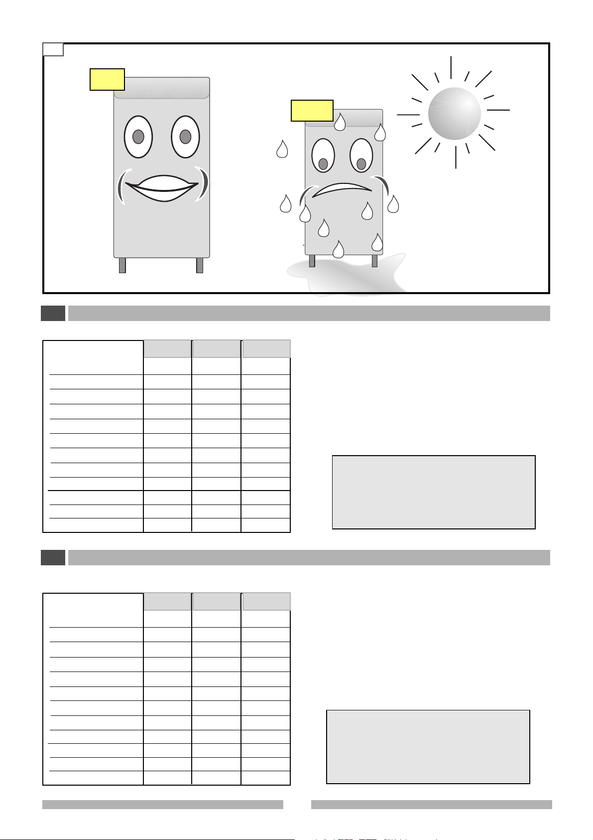
3.2 FUSIBILI
Modello
110 SH
750 SV Vip/plus
370 SH
340 SV (plus)
500 SV (plus)
550 SH
110 H
750 Vip/plus
370 H
340 V/plus
500V/plus
550 H
Simbolo Valore
FU
FU
FU
FU
FU
FU
FU
FU
FU
FU
FU
FU
6 A
6 A
6 A
6 A
6 A
6 A
10 A
10 A
10 A
10 A
10 A
10 A
Codice
TT
TT
TT
TT
TT
TT
TT
TT
TT
TT
TT
TT
>30°C
PO1207-140
3.3 CONDIZIONI AMBIENTALI
Per il corretto funzionamento dell’apparecchiatura è necessario che il posizionamento rispetti i seguenti requisiti:
• lontano da fonti di calore,
• lontano dai raggi diretti del sole,
• lontano dai sistemi di condizionamento,
• ambiente non polveroso.
Temperatura ambiente min: +10°C (*)
max + 30°C
Umidità relativa UR max 80%
(*) La temperatura ambiente non deve essere infe
riore al set point impostato.
3 TECHNICAL SPECIFICATIONS
GB
3.2 FUSES
Model
110 SH
750 SV Vip/plus
370 SH
340 SV (plus)
500 SV (plus)
550 SH
110 H
750 Vip/plus
370 H
340 V/plus
500V/plus
550 H
514903
Symbol Value Code
FU
FU
FU
FU
FU
FU
FU
FU
FU
FU
FU
FU
6 A
6 A
6 A
6 A
6 A
6 A
10 A
10 A
10 A
10 A
10 A
10 A
TT
TT
TT
TT
TT
TT
TT
TT
TT
TT
TT
TT
3.3 ENVIRONMENTAL CONDITIONS
In order for the appliance to operate correctly , it should be placed
in a site with the following requisites:
•far from heat sources,
•far from direct sunlight,
•far from air conditioning systems,
• in a dust-free ambient.
Ambient temperature min: +10°C (*)
max + 30°C
Relative humidity RH max 80%
(*) The ambient temperature must not be inferior to
the chosen set-point.
8
3.2
145
A
PLA1910-020
I
3 CARATTERISTICHE TECNICHE
B
3.4 DISEGNI TECNICI DI LAY-OUT
A= Lato muletto
B= Lato transpallet
145
B
A
PLA1910-010
A
B
CE70017a
3 TECHNICAL SPECIFICATIONS
GB
3.4 TECHNICAL LAY-OUT DIAGRAMS
A= Fork lift truck side
B= Transpallet side
9
514903

4.1
DS1710-010
4 MOVIMENTAZIONE E DISIMBALLO
I
4.2 4.3
40° C
0°C
4.1 REQUISITI DEL PERSONALE
Per la movimentazione della macchina non sono richiesti particolari requisiti da parte del personale addetto allo scopo (tenere
presente la tipologia dell’imballo).
Si raccomanda comunque di far eff ettuare tale operazione a chi
abitualmente utilizza mezzi di sollevamento e trasporto.
4.2 STATO DELLA MACCHINA
La macchina viene fornita normalmente imballata e pallettizzata.
Nel caso di consegna da parte di nostro personale la macchina
può anche essere priva di imballo.
Altri tipi di imballo possono essere forniti in base alla destinazione e/o esigenze del cliente
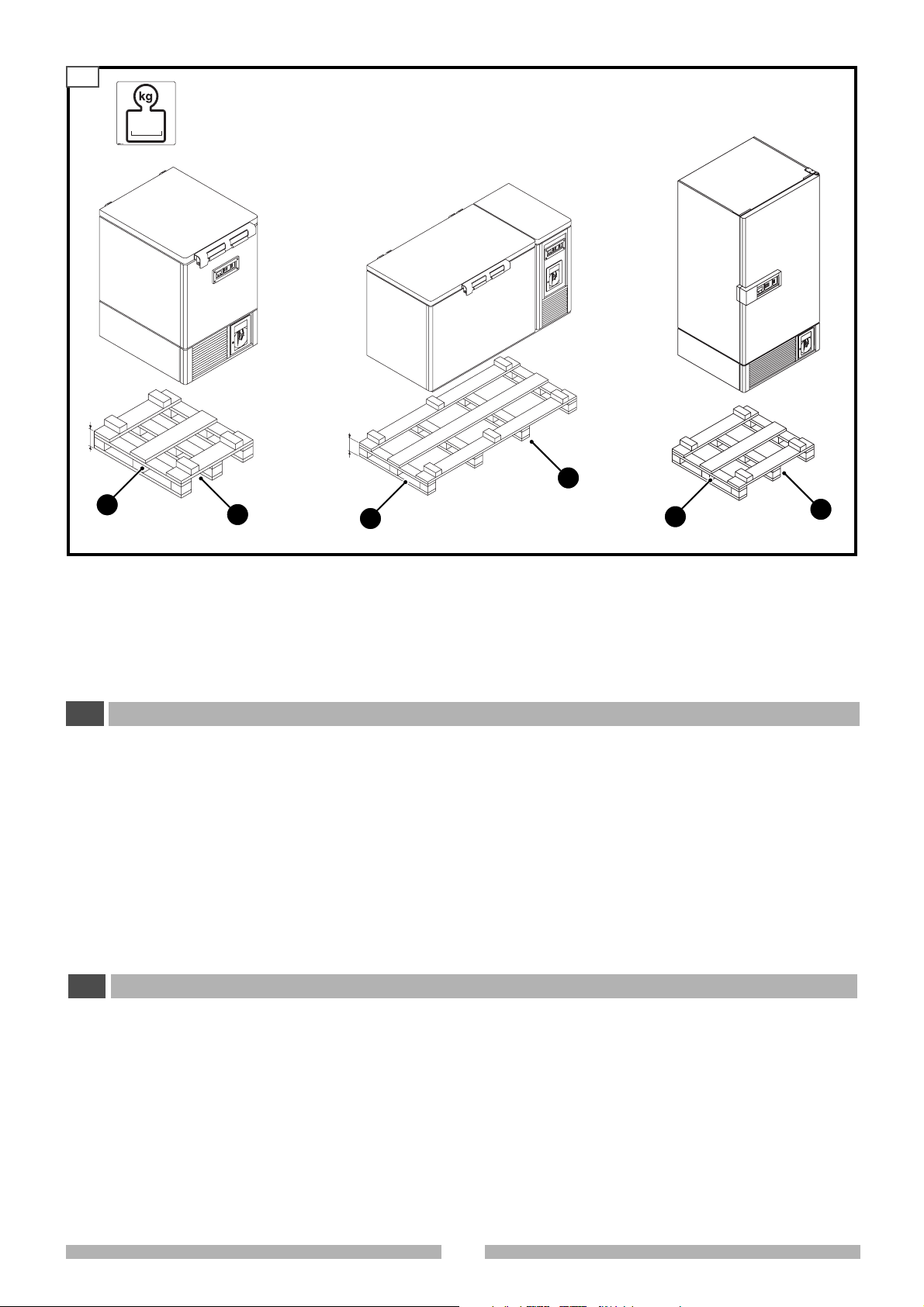
4.3 MEZZI NECESSARI PER LA MOVIMENTAZIONE
La macchina può essere sollevata e movimentata con carrello
elevatore, carroponte , gru o altro mezzo idoneo av ente una portata adeguata.
Verificate l'assetto delle forche e la stabilità del carico
prima di movimentare la macchina.
DS1710-050
DS1710-060
Per la movimentazione osservate sempre le seguenti norme:
•Movimentate lentamente la macchina.
• Non inclinate la macchina ma tenetela sempre in posizione
verticale.
• Siate sicuri di controllare sempre la macchina durante la
movimentazione.
Attenzione:
• Non rovesciare la macchina
• Non trascinare la macchina
• Non provocare scossoni alla macchina.
Stoccaggio della macchina
E’ opportuno che l’ambiente di conservazione sia ben asciutto
con temperature comprese fra 0° ÷ 40° C.
Non sovrapponete più macchine imballate e mantenete la
posizione verticale indicata dalle frecce apposte sull’imballo
stesso.
Assicuratevi che le forche non urtino il telaio della macchina.
In caso di urto accidentale controllate immediatamente
eventuali danni, se è il caso contattare il costruttore.
4 HANDLING AND REMOVAL OF PACKAGING
GB
4.1 PERSONNEL REQUISITES
Personnel in charge of handling the machine need no special
requisites (just remember the type of packaging).
However, we suggest that this is done by someone who is
accustomed to using machines for lifting and transport operations.
4.2 MACHINE CONDITIONS
The machine is normally supplied packed and on a pallet. If the
machine is delivered by our staff, it may be without packaging.
Other types of packaging may be supplied according to the
destination and/or customer’s needs.
4.3 EQUIPMENT NEEDED FOR HANDLING
The machine can be raised and moved by a lift truck, bridge
crane, crane or other suitable means with an adequate capacity.
Check that the forks are level and the load is stable
before moving the machine.
514903
In order to handle the machine, the following rules should
be observed:
•Move the machine slowly
• Do not tilt the machine, always keep it in an upright position
• Always make sure y ou can control the machine during handling
Warning:
• Do not turn the machine upside-down
• Do not drag the machine
• Do not shake the machine
How to store the machine
It should be kept in a dry environment with an ambient temperature ranging from 0° ÷ 40° C.
Do not place packaged machines one on top of the other and
always keep them in an upright position as indicated by the special
arrows marked on the packaging itself.
Make sure that the forks do not hit the machine frame.
If it is hit accidentally, check immediately for any damage
and if necessary, contact the manufacturer.
10
4.4
PLA1910-050
PLA1910-040
PLA1910-060
2
PLA1910-030
1
PLAT500-050
2
1
4MOVIMENTAZIONE E DISIMBALLO
I
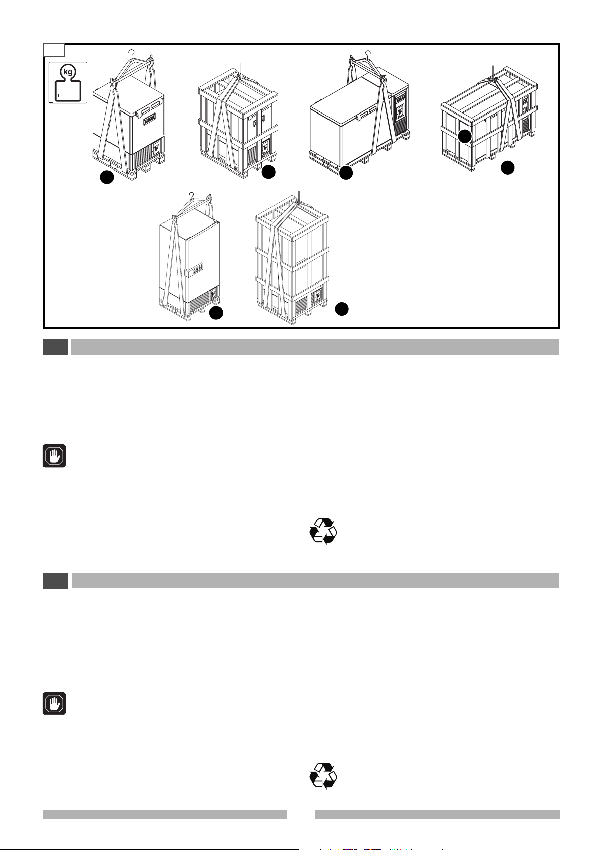
4.4 SOLLEVAMENTO E MOVIMENTAZIONE CON
CARROPONTE
Accessori: cinghie in fibra tessile ed angolari in PVC.
peso: vedere dati tecnici
Schemi di imbracatura
1 senza imballo
2 con imballo
Non imbracate la macchina con funi metalliche o catene
in quanto possono danneggiarla.
Non imbracare mai la macchina senza pallet. Al fine di
evitare che l’olio contenuto nel compressore defluisca
nel circuito refrigerante, trasportate, immagazzinate e
movimentate l’apparecchiatura esclusivamente in posizione verticale, rispettando le indicazioni poste sull’imballo. Se la macchina viene coricata lasciatela in posizione verticale per almeno 24 ore prima di metterla in
funzione.
4.5 DISIMBALLO
La macchina viene resa pronta per il funzionamento.
4 HANDLING AND REMOVAL OF PACKAGING
GB
4.4 HOW TO RAISE AND MOVE WITH A BRIDGE
CRANE
Accessories: textile fibre belts and PVC angle bars.
Weight: see technical specifications
Diagram of slings
1 Without packaging
2 With packaging
Do not use place the machine in a sling of metal cables
or chains as these could damage it.
Never put a sling around a machine without its pallet.
In order to prevent the oil in the compressor from flowing
into the refrigerating circuit, only transport, stock and
handle the equipment in an upright position according
to the instructions on the packaging. If the machine is
placed on its side, leave it in an upright position for at
least 24 hours before switching on.
1
PLAT500-060
2
2
Prima di togliere la macchina dall’imballo controllare che non
abbia subito danni durante il trasporto.
In tal caso:
a) Contattare il rappresentante di zona
b) Fare un rapporto scritto allegando se possibile delle fotogra-
fie che evidenziano il danno subito
c) Spedite una copia del rapporto a:
Compagnia di assicurazione del trasportatore
Compagnia di trasporti
Costruttore o rappresentante di zona
• Rimuovere tutte le parti dell’imballo e smaltirle in base alle
leggi vigenti.
• Eliminare le parti con chiodi ed eliminare sacchi e film in
materiale plastico.
Tutti i materiali dell'imballo sono riciclabili e possono
essere smaltiti in base alle disposizioni vigenti. Abbiate cura di eliminare le parti dell'imballo in modo che
queste non costituiscano pericolo e inoltre eliminate i
sacchi di plastica in quanto possono essere pericolosi
per i bambini (soffocamento).
4.5 REMOVAL OF PACKAGING
T
he machine is delivered ready-to-go.
Before removing the machine from its packaging, chec k that it has
not been damaged during transport.
If so:
a) Contact your area representative
b) Make a written report and if possible attach photographs showing
the damage
c) Send a copy of the report to:
Shipping agent insurance company
Shipping agent
Manufacturer or area representative
• Remove all the packaging and destroy according to the laws in
force.
•Eliminate the parts with nails and eliminate plastic bags and
plastic sheeting.
All the packaging materials can be recycled and can be
disposed of according to the regulations in force. Take
care to eliminate the packaging so that it does not
become a danger and throw away the plastic bags, as
they could cause children to suffocate.
11
514903
4.5
4.6
DS1710-010
4.7
DS1710-090
4 MOVIMENTAZIONE E DISIMBALLO
I
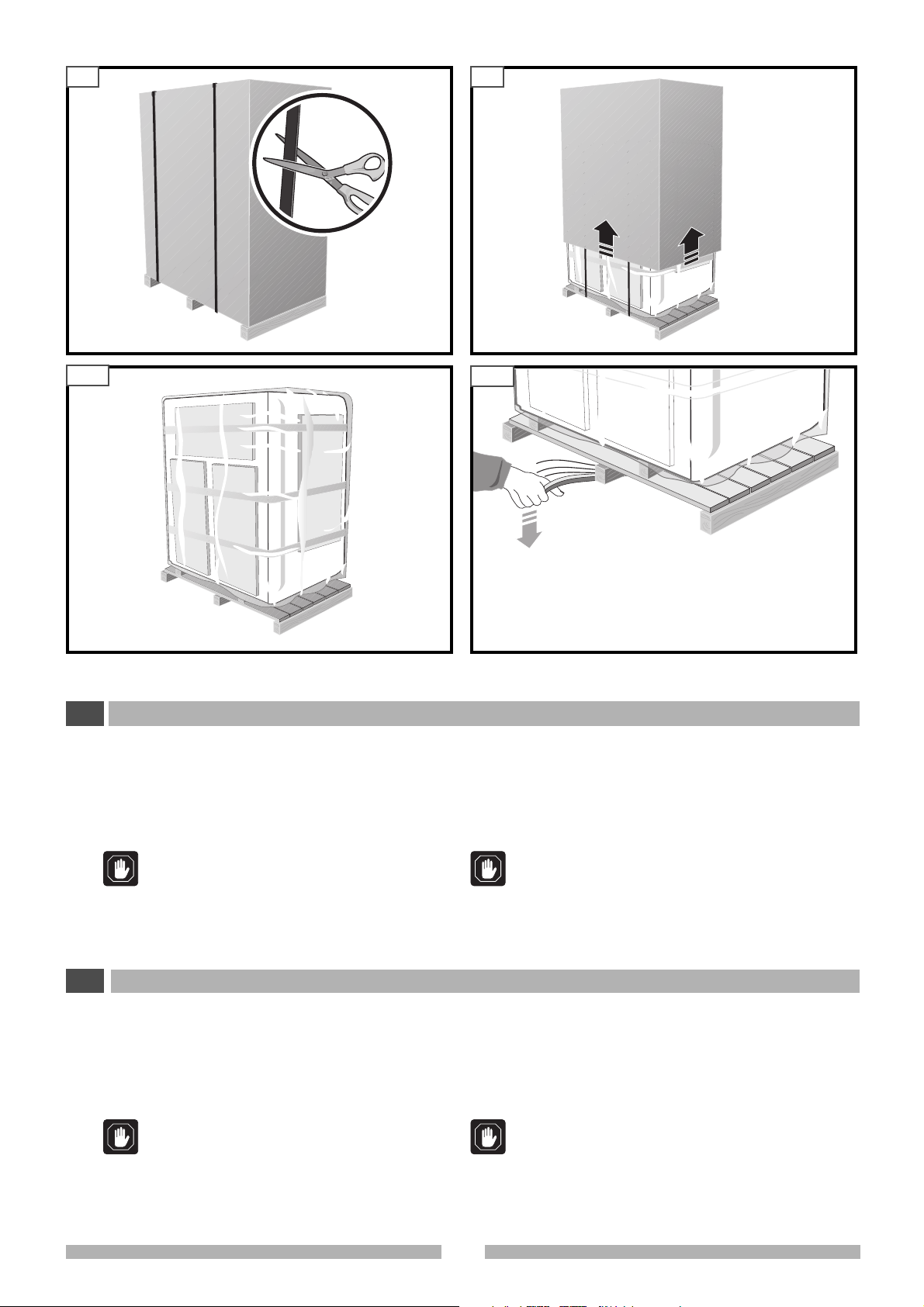
4.5.1 Rimozione reggette esterne (Fig.4.5)
4.5.2 Estrazione cappello in cartone (Fig.4.6)
DS1710-040
4.8
4.5.4 Rimozione blocchi in legno laterali (Fig.4.8)
• Togliete le viti che bloccano i listelli sull'armadio.
• Utilizzate una leva specifica per rimuovere i due blocchi di
legno.
DS1710-030
DS1710-070
4.5.3 Rimozione plastica (Fig.4.7)
Nel rimuovere la plastica, ponete attenzione a
non graffiare la superficie della macchina.
4 HANDLING AND REMOVAL OF PACKAGING
GB
4.5.1 How to remove the outer straps (Fig.4.5)
4.5.2 How to remove the cardboard casing (Fig.4.6)
4.5.3 Removal of plastic materials (Fig.4.7)
When removing the plastic materials, make sure
that you don’t scratch the surface of the appliance.
514903
Ponete attenzione a non graffiare la superficie della
macchina.
4.5.4 How to remove the wooden side blocks (Fig.4.8)
• Remove the screws that block the ledges on the cabinet.
• Use a special lever to remove the two wooden blocks.
Take care not to scratch the surface of the machine.
12

4.9
4 MOVIMENTAZIONE E DISIMBALLO
I
4.10
P
DS1710-080
PLATF5482
4.5.5 Rimozione pallet
• Sollevate di qualche centimetro la macchina, quanto basta
per sfilare il pallet.
• La macchina può essere posta direttamente a pavimento.
Non urtate e non graffiate la macchina
In caso di urto accidentale controllate immediatamente
eventuali danni, se è il caso contattare il costruttore.
MOVIMENTAZIONE MANUALE
Tutti i modelli sono supportati da quattro ruote, pertanto è possibile spostarli manualmente.
Prima di compiere lo spostamento della macchina attuare tutte
le precauzioni necessarie:
•Tenete conto della massa da movimentare e quindi del relati-
4 HANDLING AND REMOVAL OF PACKAGING
GB
4.5.5 How to remove the pallet
•Just raise the machine a few centimetres so that the pallet
can be pulled out from underneath.
• The machine can be placed directly on the floor.
Do not bang or scratch the machine
In case of accidental bumps, please check is there is any
damage and, should it be necessary, contact the
manifacturer.
MANUAL HANDLING
All models are supported by four wheels; it is theref ore possib le
to move manually.
Before moving the equipment:
• Bear in mind the mass which has to be moved and calculate
vo numero di persone necessarie a controllarne la massa
durante lo spostamento;
•verificate che il pavimento sia liscio e in piano.
4.6 IMMOBILIZZAZIONE DELLA MACCHINA
La macchina non deve essere bloccata al suolo.
Controllate sempre che il pavimento sia in piano
Per evitare spostamenti indesiderati, livellate e stabilizzate la
macchina con i piedini P anteriori con l'utilizzo di un’apposita
chiave (fig. 4.10)
the number of people needed to control the mass during
movement.
• check that the floor is smooth and completely flat.
4.6 HOW TO BLOCK THE MACHINE
The machine must not be fixed to the floor.
The machine has been designed to operate on a horizontal floor.
In order to prevent the machine from moving accidentally, use
correct spanner to adjust the small front feet P so that the machine
is level and perfectly stable (fig. 4.10).
13
514903
5.1
1
1
1
PL1810-01
5.2
1
5
1
5
2
6
3
5
6
6
5
5
5
3
2
4
2
2
2
4
3
2
4
44
4
5.3 5.4
A
B
7
10
18
6.1
11
11
8
PLAT_F0900
12
6.2
PLAT_F0898
18
PLAT_F0880c
5 DESCRIZIONE DEL SISTEMA
I
10
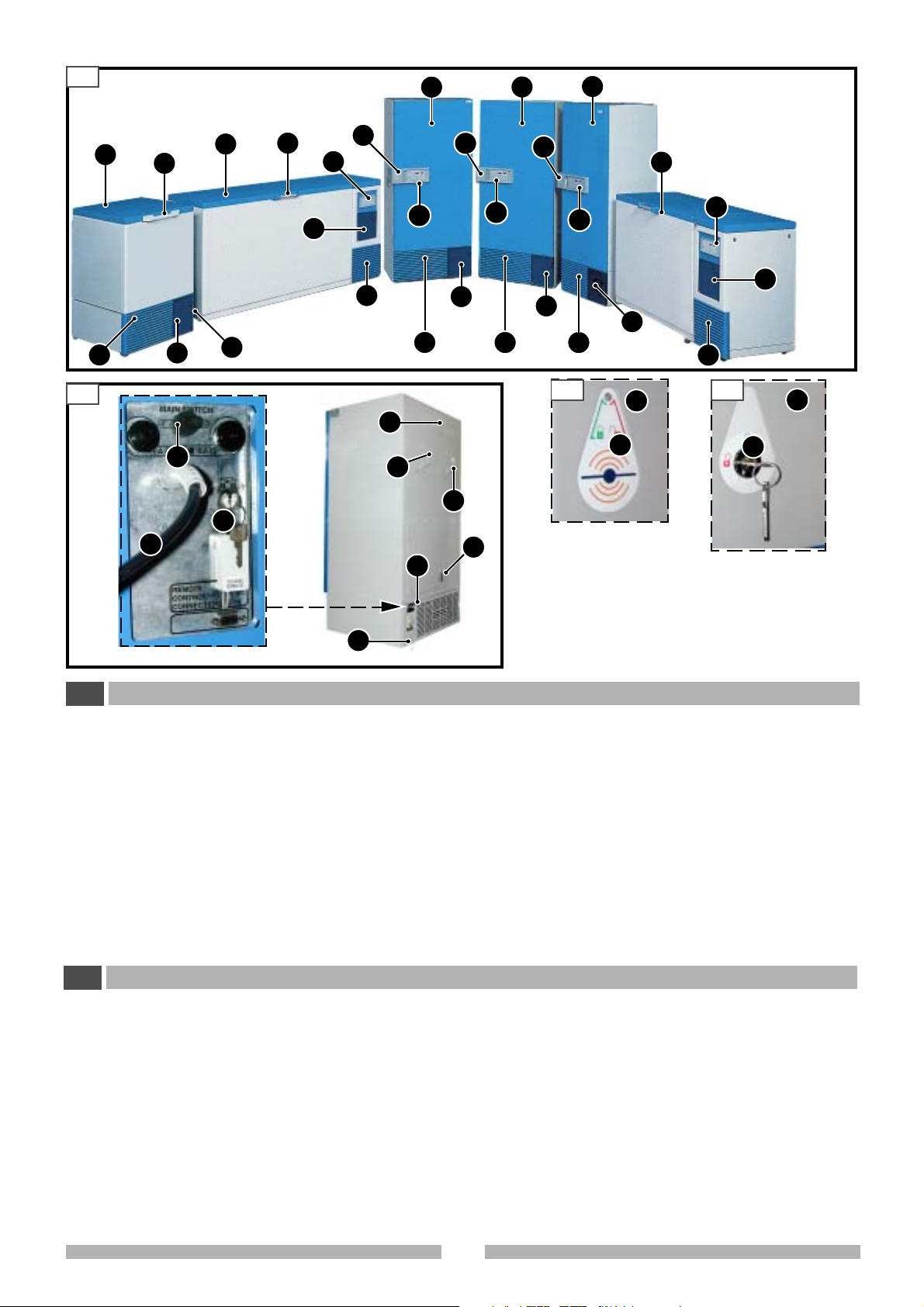
5.1 VISTA GENERALE
1 Porta di accesso
2 Registratore grafico (opzionale)
3 Pannello comandi
4 Griglia protezione condensatore
5 Maniglia per apertura sportello
6Chiusura
6.1 Chiusura con sistema BIOGUARD (mod. Plus)
6.2 Chiusura con chiave
7 Attacco LN2/CO2
8
Attivazione/disattivazione sistema Bioguard e blocco/sblocco
pannello comandi (solo per modelli PLUS)
10 Cavo di alimentazione
11 Distanziatori
5 DESCRIPTION OF THE SYSTEM
GB
5.1 GENERAL VEW
1Access door
2 Chart recorder (optional)
3 Control panel
4 Condenser protection grid
5 Handle to open door
6 Door closed
6.1 With the Bioguard system (PLUS model)
6.2 With a key
7 LN2/CO2 connection
8 Activation/deactivation of the Bioguard system and locking/
unlocking of the control panel (PLUS models only)
10 Supply cable
11 Spacers
12 Valvola di compensazione (compensa la differenza di pres-
sione esterna-interna facilitando l'apertura della porta).
18 Interruttore generale
La struttura è interamente metallica realizzata in lamiera di
acciaio zincato e verniciata con resine epossidiche.
La porta 1 è realizzata nella stessa maniera, il lato interno 9 è in
polistirolo ad urto resistente termoformato, la guarnizione è del
tipo con tenuta magnetica.
Nella parte posteriore sono situati i distanziatori 11 che permet-
tono al congelatore di avere una distanza dal muro sufficiente
per la circolazione dell'aria.
A=Chiusura con sistema BIOGUARD
B=Chiusura con CHIAVE
12 Compensating valve (this compensates the difference in
external and internal pressure and helps the door to open).
18 Main switch
The structure is completely metallic made of galvanised sheet
steel painted with epoxy resins.
The door 1 has the same features as the main body, inside 9 it
is insulated with thermoformed, high impact polystyrene and
has a magnetic gasket.
The spacers 11, located behind the machine, ensure there is
enough room between the freezer and the wall to allow a
sufficient circulation of air.
A=Door closed with the BIOGUARD system
B=Door closed with a KEY
514903
14
5.5 5.6
5.5
14
17
16
14
PLATF2108
5.7
14
14
5.5.1
9
14
PLATF2109
17
17
5.8
15
15
14
14
14
9
PLATF2110
PO1207-F13
5 DESCRIZIONE DEL SISTEMA
I
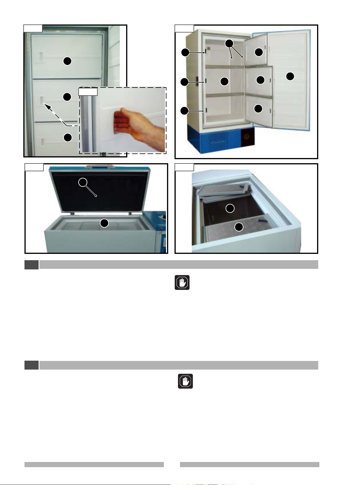
5.2 VISTA INTERNA
La vasca interna 15 è realizzata con acciaio inox AISI 304.
L’apparecchiatura prevede dei controsportelli 14 impiegati per
aumentare il grado di isolamento termico.
1 Porta di accesso
9 Lato interno porta
14 Controsportelli
15 Vasca interna
16 Cremagliere per ripiani
17 Magneti
5 DESCRIPTION OF THE SYSTEM
GB
5.2 INTERNAL VIEW
The inner storage compartment 15 is made of AISI 304 stainless
steel.
The appliance is equipped with inner doors or lids 14 used to
increase the thermal insulation grade.
1Access door
9Door internal side
14 Inner doors
15 Inner storage compartments
16 Shelves racks
17 Magnets
PO1207-F12
Attenzione! Se tenete i controsportelli aperti troppo a
lungo, sulla guarnizione si formano delle gocce di acqua
che poi, congelano e possono bloccare l’apertura.
Asciugare le guarnizioni e la superficie di contatto sulla
struttura prima di chiudere i controsportelli.
All’interno della struttura sono sistemati dei ripiani regolabili in
altezza a seconda delle esigenze del cliente.
Warning!
If keep open the inner door too long, the water drops
are formed on the gasket. When the drops freeze,
the ice can block the inner door, so clean and dry the
gasket and the inner door knoker before close.
The shelves inside the main body can be adjusted in height
according to the customer’s needs.
15
514903
 Loading...