


UN-RELEASED REVIEW COPY 2/20/98
Downloaded from - http://www.guardianalarms.net
© 1998, Andover Controls Corporation
All Rights Reserved
No part of this publication may be reproduced, read or stored in a retrieval system, or transmitted, in any form or by any means, electronic, mechanical, photocopying, recording, or otherwise, without prior written permission of Andover Controls Corporation.
Produced in the United States of America.
Infinity is a trademark of Andover Controls Corporation. All other trademarks are the property of their respective owners.
Continuum I/O Reference, Version: REVIEW February, 1998
Andover Controls part number: 30-3001-499
The information in this book is furnished for informational purposes only, is subject to change without notice, and should not be construed as a commitment by Andover Controls Corporation. Andover Controls Corporation, assumes no liability for any errors or inaccuracies that may appear in this document.
Related Documents
Continuum Power Supply Reference, 30-3001-702
Continuum CPU Reference, 30-3001-701
Continuum Display Module Reference, 30-3001-711
Andover Controls Corporation 300 Brickstone Square Andover, MA 01810
(978) 470-0555 fax: (978) 470-0946
Andover Controls Corporation
Radio Interference
This equipment has been tested and found to comply with the limits for a Class A digital device, pursuant to Part 15 of the FCC Rules. These limits are designed to provide reasonable protection against harmful interference when the equipment is operated in a commercial environment. This equipment generates, uses, and can radiate radio frequency energy and, if not installed and used in accordance with the instructions in this manual, may cause harmful interference to radio communications. Operation of this equipment in a residential area is likely to cause harmful interference in which case the user will be required to correct the interference at his own expense.
Note
This digital apparatus does not exceed the Class A limits for radio noise emissions from digital apparatus set out in the Radio Interference Regulations of the Canadian Department of Communications.
Avis
Le présent appareil numérique n’émet pas de bruits radioélectriques dépassant les limites applicables aux appareils numériques de la class A prescrites dans le Règlement sur le brouillage radioélectrique édicté par le ministère des Communications du Canada.
Continuum I/O System Reference
Andover Controls Corporation
Contents
Introduction...................................................................... |
1 |
Mechanical Installation.................................................... |
4 |
Overall Dimensions .................................................................... |
7 |
Door-Mounted Modules.............................................................. |
8 |
Power-CPU Connections............................................... |
10 |
Connection of I/O Modules....................................................... |
11 |
Maximum Number of I/O Modules............................................ |
12 |
Maximum Length of I/O Bus..................................................... |
12 |
Connecting Remote I/O Modules with RS-485......................... |
12 |
Termination Guidelines ............................................................ |
13 |
Individual Module Characteristics................................ |
17 |
General Wiring Concerns......................................................... |
17 |
INPUT Modules |
|
UI-8-10 / UI-8-10-10V ................................................................. |
19 |
DI-6-AC / DI-6-AC-HV ................................................................ |
35 |
DI-8 ............................................................................................ |
43 |
MI-6............................................................................................ |
53 |
OUTPUT Modules |
|
DM-20 ........................................................................................ |
61 |
AO-4-8 / AO-4-8-O ..................................................................... |
73 |
DO-4-R / DO-4-R-O .................................................................... |
83 |
DO-6-TR .................................................................................... |
91 |
LO-2 / LO-2-O ............................................................................ |
99 |
MIXED Modules |
|
AC-1......................................................................................... |
113 |
Continuum I/O System Reference
Andover Controls Corporation

ÈNTINUUM
I/O Systems
This manual describes the installation, care and use of all Continuum I/O modules.
The Continuum Ethernet-based intelligent building system allows you to mix and match various combinations of DIN rail-mounted modules¾high density I/O, CPU and power supply, and your choice of several user interface modules¾in a single controller location to meet your building’s control and monitoring needs. With the Continuum system, as your network grows, simply add or replace I/O modules as needed.
The Continuum I/O modules feature a sleek, lightweight casing designed for natural convection cooling, and a 3-position front cover for easy, hands-free access. Built-in quick-release fasteners at the back of each I/O module are provided for DIN rail mounting¾no tools required. These fasteners also snap into a locked position for panel mounting. Input and output connectors are located at the bottom of each I/O module and are removable for easy field access and maintenance. All Continuum modules are designed for mounting in an optional NEMA 1-style Continuum enclosure.
The Continuum I/O modules communicate with the Continuum NetController CPU module. Like all Continuum modules, the I/O modules snap together directly via built-in connectors on either side so network expansion is quick and easy. Both power transmission and communication signals between the Continuum power supply module, NetController CPU module, and all I/O modules feed through this connection. For added convenience in certain applications, such as door control or lighting control, a single module or groups of I/O modules can be remotely located and connected using approved cable and powered from a local 24 VDC power supply. Each I/O module features its own push-button for quick and easy network commissioning.
This document covers the standard Input and Output modules. For information regarding the special Continuum enclosure door-mounted display modules consult the Andover Controls Continuum Display Module Reference.
Continuum I/O System Reference 1

I/O System Introduction
The Continuum I/O system is comprised of a series of modules separated by function that connect via a common electrical communications bus. Each functional component is enclosed in a plastic case containing all of its connections to the outside world. Modules are connected to a central controller via a standard five conductor connector.
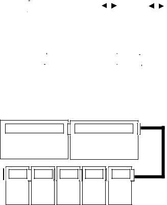
The Continuum system includes at least one power supply and a single controller module. I/O modules provide the controller with the ability to interface with the outside world. They connect directly and communicate with the CPU. The following is a typical architecture drawing of a Continuum System:
Power Supply |
|
Controller |
|
I/O Modules |
||
|
|
|||||
|
|
|
|
|
|
|
|
|
|
|
|
|
|
|
|
|
|
|
|
|
|
|
|
|
|
|
|
|
|
|
|
|
|
|
|
|
|
|
|
|
|
|
|
|
|
|
|
|
|
|
|
|
|
|
|
|
|
|
|
|
|
|
|
|
|
|
|
|
|
|
|
|
|
|
|
|
|
|
|
|
|
|
|
|
|
|
|
|
|
|
|
|
|
|
|
|
|
|
|
|
|
|
|
|
Continuum I/O modules are available in INPUT, OUTPUT, MIXED and DISPLAY varieties.
2 Andover Controls
The INPUT modules available are:
∙UI-8-10; Universal Input Module
∙UI-8-10-10V; Universal Input Module
∙DI-6 AC; AC Digital Input Module
∙DI-6 AC HV; AC Digital Input Module
∙DI-8; Digital Input Module
∙DM-20; Digital Input/Output Module (for DIO-20)
∙MI-6; MilliAmp Input Module
The OUTPUT modules available are:
∙AO-4-8-O; Analog Output Module (with override)
∙AO-4-8; Analog Output Module
∙DO-4-R-O; Relay Output Module (with override)
∙DO-4-R; Relay Output Module
∙DO-6-TR; Triac Output Module
∙LO-2-O; Lighting Output Module (with override)
∙LO-2; Lighting Output Module
The MIXED modules available are:
∙AC-1; Door, Access Control, Wiegand Module
∙AC-1-ABA; Door, Access Control, ABA Module The DISPLAY modules available are:
∙LB-8; 8-Channel LED Bar Display/ 8 Push Button Module
∙LS-8; 8-Channel, 3 Digit 7-Segment LED Display/ 16 Push Button Module
∙LC-1; 2-Line LCD Display/ 12 Push Button Module
∙VM-1; Voice Record and Playback Module
∙GA-40; Graphic Annunciator Panel
Continuum I/O System Reference 3
Mechanical Installation
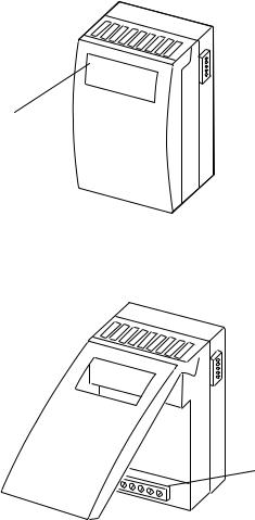
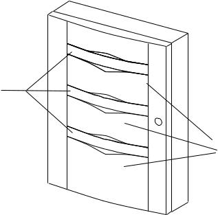
Each I/O module, except the Display variety, is enclosed in the same standard plastic case that is designed to be mounted on a standard DIN rail or fastened to a panel.
Note: In order to meet agency requirements, it is necessary that the modules along with the power supply and controller be housed in another metal enclosure i.e., a NEMA box or the new Andover Controls Continuum enclosure.
The standard I/O module plastic case is illustrated below:
Status Indicators & some switches
Status indicators and operator switches are located on the indicator panel. Other switches available for module configuration may be accessed by lifting the hinged door to the module as shown.
Connections to controlled/sensed equipment
4 Andover Controls
Wiring to controlled points or sensors is accomplished via a standard removable screw terminal block located at the bottom of the module behind the door. An open area at the bottom of the case allows wires to exit in an appropriate manner.
On the back of each module are molded DIN rail guide fingers. The design allows the module to easily hook onto and slide along a standard DIN rail.
Locking Fingers
With the mounting brackets extended outward, hook the module onto the DIN rail as shown below:
Continuum I/O System Reference 5
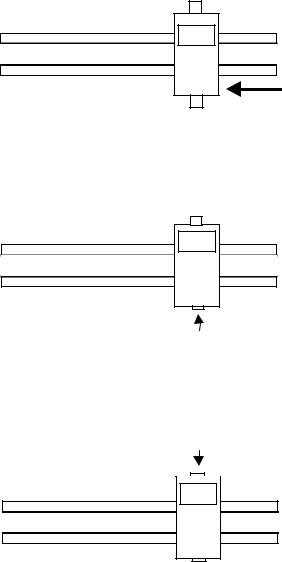
Slide the module into position.
Press the lower mounting bracket inward until it locks the module in place.
Press the upper bracket into its locked position as well.
Once the module is in the desired position, it is locked to the rail by pushing the bottom clamps inward. After the bottom is secure, press the top clamp inward to complete the operation.
6 Andover Controls
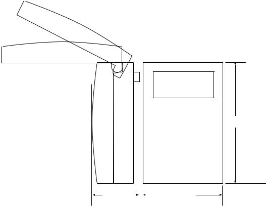
Overall Dimensions
The overall dimensions of the standard I/O case are as shown:
6.70'' (170.2 mm)
|
|
|
|
|
|
|
|
|
|
|
|
|
|
|
|
|
|
|
|
|
|
|
|
|
|
|
|
|
|
|
|
|
|
|
|
|
|
|
3.50 '' |
2.50 '' |
|
|
|
|
|
|
|
(63.5 mm) |
|
|
|
|
(88.5 mm) |
||
|
|
|
|
|
|
|
|
|
|
|
|
|
|
|
|
|
|
|
|
|
|
|
|
Continuum I/O System Reference 7
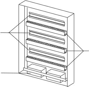
Enclosure-Mounted Modules
The modules that are designed to be mounted to the new Andover Controls Continuum enclosure fit into openings left by removing panels in the front door.
The new enclosure provides a place to mount a power supply, CPU and up to ten DIN rail mounted I/O modules. Several display modules can be affixed to the front panel.
The enclosure is a 6” deep NEMA box with integral display panels, DIN rails, cable troughs and a battery storage compartment.
DIN Rail
Cable Trough
Battery
Storage
The enclosure features three DIN rails and cable management accessories. Use of the new enclosure is not required, however, it provides a convenient method of constructing small local systems.
8 Andover Controls
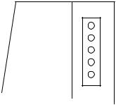
The front door of the enclosure contains removable sections into which special operator display and control modules may be mounted. Alternately, Plexiglas panels may be used to view the status lights of all internal modules when the door is closed.
Removable
Display Panels
Spacers for
Additional Displays
Continuum I/O System Reference 9
Power-CPU Connections
The Continuum NetController CPU module includes a connector on the upper right side of its case for further distribution of the 24 VDC input power and special I/O communications signals to all I/O modules. Continuum I/O modules use these signals for power and communications as well.
The power-I/O connector is a five pin male assembly that is designed to easily insert directly into the left side (input) connector of any I/O module. The signals within that connector are as follows:
PIN |
Function |
|
5 |
+24 VDC |
5 |
4 |
24 VDC Return |
|
3 |
Ground |
|
2 |
Comm B |
|
1 |
Comm A |
|
The system power supply generates a +24 VDC source for all modules in the system. This power source is received through the input power connector on the left side of the CPU module and sent through to pins 4 and 5 of this connector. Pin 3 (Ground) is intended as a signal ground connection.
Communications between the CPU and I/O modules is through a two-signal serial interface that can be internally configured as either RS 485 or Echelon LON FTT-10. Pins 1 and 2 (Comm B and Comm A) provide the electrical connection for this interface.
10 Andover Controls
Connection of I/O Modules
The CPU can directly connect to I/O without the use of cables through a system of built-in plugs and jacks. All I/O modules include two complementary module interconnectors.
Creating a system is as simple as physically plugging the modules together.
|
Power Supply |
|
|
|
|
|
|
|
|
|
|
|
|
|
|
|
|
|
|
|
|
|
|
|
|
|
|
|
|
|
|
|
|
||
|
|
|
|
|
|
|
|
|
|
|
|
|
|
|
|
|
|
|
|
|
|
|
|
|
|
|
|
|
|
|
|
|
|||
|
|
|
|
|
|
|
|
|
|
|
|
|
|
|
|
|
|
|
|
|
|
|
|
|
|
|
|
|
|
|
|
|
|||
|
|
|
|
|
|
|
|
CPU |
|
|
|
|
|
|
|
|
|
|
|
|
|
|
|
|
|
|
|
|
|
|
|
|
|||
|
|
|
|
|
|
|
|
|
|
|
|
|
|
|
|
|
|
I/O |
|
|
|
|
|
|
|
|
|
|
|
||||||
|
|
|
|
|
|
|
|
|
|
|
|
|
|
|
|
|
|
|
|
|
|
|
|
|
|
I/O |
|
|
|||||||
|
|
|
|
|
|
|
|
|
|
|
|
|
|
|
|
|
|
|
|
|
|
|
|
|
|
|
|
|
|
|
|
||||
|
|
|
|
|
|
|
|
|
|
|
|
|
|
|
|
|
|
|
|
|
|
|
|
|
|
|
|
||||||||
|
|
|
|
|
|
|
|
|
|
|
|
|
|
|
|
|
|
|
|
|
|
|
|
|
|
|
|
|
|
|
|
|
|
|
|
|
|
|
|
|
|
|
|
|
|
|
|
|
|
|
|
|
|
|
|
|
|
|
|
|
|
|
|
|
|
|
|
|
|
|
|
|
|
|
|
|
|
|
|
|
|
|
|
|
|
|
|
|
|
|
|
|
|
|
|
|
|
|
|
|
|
|
|
|
|
|
|
|
|
|
|
|
|
|
|
|
|
|
|
|
|
|
|
|
|
|
|
|
|
|
|
|
|
|
|
|
|
|
|
|
|
|
|
|
|
|
|
|
|
|
|
|
|
|
|
|
|
|
|
|
|
|
|
|
|
|
|
|
|
|
|
|
|
|
|
|
|
|
|
|
|
|
|
|
|
|
|
|
|
|
|
|
|
|
|
|
|
|
|
|
|
|
|
|
|
|
|
|
|
|
|
|
|
|
|
|
|
|
|
|
|
|
|
|
|
|
|
|
|
|
|
|
|
|
|
|
|
|
|
|
|
|
|
|
|
|
|
|
|
|
|
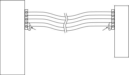
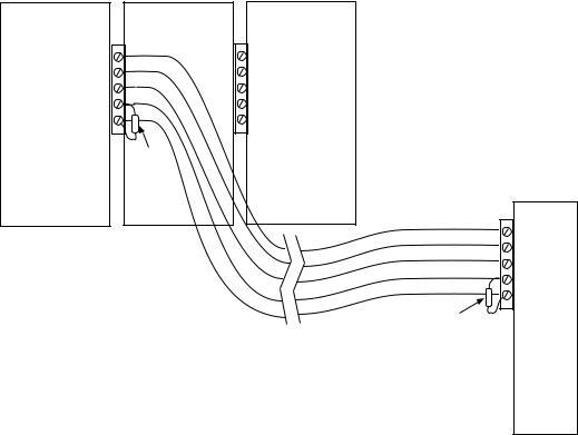
In vertical extended systems, I/O modules may be located above or below other modules. In this case, cable assemblies bridge the I/O modules together.
The cable necessary to connect the CPU and external I/O modules is five conductor and would be attached using a plug-in screw terminal connector. Connection between the modules is one-to-one straightforward wiring as shown below:
5 |
|
5 |
|
||
4 |
|
4 |
|
||
3 |
|
3 |
|
||
2 |
|
2 |
|
||
1 |
|
1 |
|
This connector is available from Andover Controls under part number 01-2050-283; Wieland manufactures it under part number 25.340.0553.0.
Continuum I/O System Reference 11
Maximum Number of I/O Modules
There is no operational limit to the number of I/O modules connected to the CPU except the capacity of the power supply. It is possible to insert auxiliary power supplies into the I/O bus to increase the number of modules supported.
To determine the maximum number of I/O modules your system can support, subtract the power requirements for each module from the maximum available from your power supply.
∙PS 120/240 AC 50 U, UPS power supply provides 35 Watts of power
∙PS 120/240 AC 50, non-UPS power supply provides 50 Watts of power
∙PS –48 DC 50, Battery operated power supply provides 50 Watts of power
∙NetController requires 15 Watts of power
Start by subtracting the NetController from the power available from your power supply.
PS 120/240 AC 50 U
35 – 15 = 20 Watts of available power for I/O
PS 120/240 AC 50
50 – 15 = 35 Watts of available power for I/O
PS –48 DC 50
50 – 15 = 35 Watts of available power for I/O
The power requirements for each I/O module is listed in the Continuum I/O System Reference Guide ACC # 30-3001-499 and can be found on individual data sheets.
Maximum Length of I/O Bus
A repeater is necessary if the cable lengths get too long. The following are recommendations regarding cable lengths for both RS-485 and FTT-10 interfaces:
RS-485 |
Repeater required if length is >2000 ft. (610 m) or after 32 modules. |
FTT-10 |
Repeater required if length is >8858 ft. (2700 m) bus topology |
|
>1640 ft. (500 m) free topology |
Connecting Remote I/O Modules with RS-485
The Continuum system allows I/O modules to be placed in a remote location from the CPU (NetController). However, long cable lengths can cause signal communications problems on the Power/I-O bus.
When locating an I/O module remotely it is necessary to add a 120 Ω terminator to the bus to compensate for the distance. The terminator must be connected at both ends of the bus for proper operation.
12 Andover Controls
Termination Guidelines
The following are typical installations that indicate the placement of the terminator:
Simple CPU and 1 remote I/O Module:
The I/O Bus that needs to be terminated is the one formed by the cable attaching the remote module to the CPU. In this case, a terminator resistor is connected across the communications lines (pins 1 & 2) directly at the NetController and again at the remote I/O module.
CPU |
5 |
|
5 |
|
|
||
|
4 |
|
4 |
|
3 |
|
3 |
|
2 |
|
2 |
|
1 |
|
1 |
|
120 Ω |
120 Ω |
Remote |
|
Resistor |
Resistor |
|
|
|
|
I/O |
|
|
|
Module |
Continuum I/O System Reference 13
CPU with local and 1 remote I/O Module:
The I/O Bus that needs to be terminated is the one formed by the cable that starts at the NetController and ends at the remote module. The bus that extends from the NetController through the local I/O stack does not need termination. In this case, the terminator resistor is connected directly across the communications lines (pins 1 & 2) at the NetController and again at the remote I/O module.
CPU |
5 |
Local |
5 |
|
I/O |
||||
|
||||
|
4 |
4 |
||
|
3 |
|
3 |
|
|
2 |
|
2 |
|
|
1 |
|
1 |
|
|
|
120 Ω |
|
|
|
|
Resistor |
|
Local
I/O
5
4
3
2
1
120 Ω
Resistor Remote
I/O
Module
14 Andover Controls
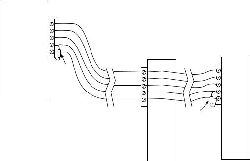
CPU with local and several remote I/O Modules:
The I/O Bus that needs to be terminated is the one formed by the cable that starts at the NetController and ends at the first remote module. The bus that extends from the NetController through the local I/O stack and the one that starts at the first remote module and extends through subsequent modules do not need termination. In this case, the terminator resistor is connected directly across the communications lines (pins 1 & 2) at the NetController and again at the first remote I/O module.
CPU |
5 |
Local |
5 |
|
I/O |
||||
|
4 |
4 |
||
|
3 |
|
3 |
|
|
2 |
|
2 |
|
|
1 |
|
1 |
|
|
|
120 Ω |
|
|
|
|
Resistor |
|
Local
I/O
|
5 |
5 |
|
4 |
4 |
|
3 |
3 |
|
2 |
2 |
|
1 |
1 |
120 Ω |
Remote |
Remote |
Resistor |
||
|
I/O |
I/O |
|
Module |
Module |
Continuum I/O System Reference 15
CPU with two remote modules separated by distance:
The I/O Bus that needs to be terminated is the one formed by both cables on either end of the first remote I/O module. In this case, the bus begins at the NetController, flows by the first remote module and ends at the second. The terminator resistor is connected directly across the communications lines (pins 1 & 2) at the NetController and again at the last remote I/O module. If the last module is actually a stack of directly connected I/O modules, the terminator is placed at the first module of the stack as indicated in the scenario described on the previous page.
CPU 5
4
3
2
1
120 Ω
Resistor
5
4
3
2
1
Remote
I/O
Module
|
5 |
|
4 |
|
3 |
|
2 |
|
1 |
120 Ω |
Remote |
Resistor |
I/O |
Module
16 Andover Controls
Individual Module Characteristics
This section of the document describes the various I/O modules and presents interfacing information. Each module is presented in its own mini-section. The part number designator for the module being described is printed on the outer edge of each page.
General Wiring Concerns for All Modules
Do not remotely ground any part of the input sensor wiring. Remote grounds connected to the return terminal could make the system operate incorrectly or damage the equipment. The signal return is not true earth ground. It is an electronic reference point necessary to interpret the sensor properly.
It is recommended that you run input wiring in a conduit separate from AC power or output wiring and avoid long wiring runs.
For reliable input operation, follow these input wiring guidelines:
∙Never lay wires across the surface of a printed circuit board.
∙Wires should never be within 1 in. or 25 mm of any component on a printed circuit board.
∙Use shielded input wire.
∙Terminate the shield of the input wires at one end of the run only—preferably at the end where your I/O module is located.
∙Be careful when stripping wire not to drop small pieces of wire inside the cabinet.
∙Don’t run your input wiring in the same conduit with AC power.
∙Don’t run your input wiring in the same conduit with your output wiring.
Grounding the Modules
Each module includes a screw terminal connection for Earth ground. It is important that this connection be made as close to the module as possible.
Caution
Do not externally ground any input signal connected to the module. This may damage the unit. Signal return terminals are not connected to Earth Ground.
Continuum I/O System Reference 17
18 Andover Controls
UI-8-10
The UI-8-10, Continuum’s universal input module, provides 8 universal inputs, software configurable as voltage, thermistor, digital, or counter point types. Each point can also be configured as a supervised input for security monitoring, providing separate indication of alarm and trouble conditions. This module is a perfect choice for any mix of temperature, pressure, flow, status points, and similar inputs in a control system, with a 0-5 volt input range and 10 bit A/D conversion.
The UI-8-10-10V model is available for 0-10V applications. It provides the identical point type selection; but is equipped with individual voltage divider DIP switches on each input, allowing each to be configured for a 0-10 volt range.
POWER
COMMISSION
COMM
STATUS
|
|
RESET |
|
|
UI-8 |
USE COPPER CONDUCTORS ONLY |
||
SWITCH SETTINGS |
|
|
INPUT TYPE |
REFERENCE |
RANGE |
TEMPERATURE |
ON |
5 V |
5V RANGE |
OFF |
5 V |
10V RANGE |
OFF |
10 V |
REFERENCE |
VOLTAGE |
|
RESISTOR |
RANGE |
|
OFF ON |
5V |
10V |
IN1
IN2
IN3
IN4
IN5
IN6
12 IN73 D IN8
|
|
|
|
|
|
R |
|
|
|
|
|
|
|
|
|
ANALOG INPUTSE |
|
|
|
|
|
||
|
|
|
|
|
|
T |
|
|
|
|
|
IN1 |
IN2 |
RET |
IN3 |
IN4 |
RET |
IN5 |
IN6 |
RET |
IN7 |
IN8 |
RET |
1 |
2 |
3 |
4 |
5 |
6 |
79 |
8 |
9 |
10 |
11 |
12 |
FEATURES
∙8 Universal Inputs
∙10 bit Resolution
∙0-5V or 0-10V Input Range
∙Supports Voltage, Thermistor, Digital, Counter and Supervised Electrical Types
∙Pull-up Resistor Disable Switches
Continuum I/O System Reference 19

UI-8-10
SPECIFICATIONS
ELECTRICAL |
|
|
Power Consumption: |
0.7 Watt at 24VDC max.; normally provided by Continuum power |
|
|
supply module. |
|
Overload Protection: |
0.5A resettable fuse with transient voltage suppressor (TVS) and |
|
|
reverse polarity protection. |
|
INPUTS |
|
|
Number of Inputs: |
8 Universal inputs; 10 bit resolution |
|
Input Types: |
Voltage, Thermistor, Digital, Counter, and Supervised |
|
Input Protection: |
24V AC/DC allowed to any single input |
|
|
(40V transient voltage suppressor on each input – UI-8-10-10V) |
|
Input Impedance: |
5 MΩ w/pull-up disabled; 10 KΩ w/pull-up enabled – UI-8-10 |
|
|
(4.4 KΩ w/pull-up enabled in 0-10V mode UI-8-10-10V) |
|
Input Connections: |
Two-piece, 13-position removable terminal block |
|
Voltage: |
UI-8-10 (0-5V) |
UI-8-10-10V (0-10V mode) |
Range: |
0-5 volts |
0-10 volts |
Resolution: |
5 mV |
10 mV |
Accuracy: |
±15 mV (±0.3% FSR) |
±40 mV (±0.4% FSR) |
Filtering: |
Corner Frequency at 15 Hz, –20 db/decade |
|
Calibration: |
Permanent (factory) |
|
Thermistor: |
10 KΩ, Type III Thermistor |
|
Type: |
||
Range: |
-30 to 230°F |
|
|
(-34 to 110°C) |
|
Resolution: |
40 to 100°F range |
0.20°F typical |
|
(4 to 38°C) |
(0.11°C typical) |
Accuracy: |
40 to 100°F range |
± 1.0°F (includes 0.36° error for thermistor) |
|
(4 to 38°C) |
(±0.55°C) |
Digital & Counter: |
|
|
Input Type: |
Contact Closure |
|
Frequency: |
4 Hz max. |
|
Pulse Width: |
125 ms min. |
|
Supervised: |
|
|
Input Type: |
Single or Double Resistor Supervision, Parallel or Series Circuit |
|
20 Andover Controls

UI-8-10
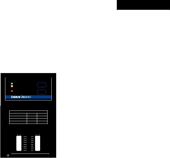
I/O Connections
The actual input connections are located on a twelve-position removable screw terminal connector located at the bottom of the module. Input wires should enter from either the top or bottom wiring troughs, and should come from the left side of the rack (by convention).
The inputs are labeled IN1, IN2, IN3, and so forth. Each pair of inputs is followed by a connection labeled RET for the input signal return, resulting in a sequence of IN1, IN2, RET, IN3, IN4, RET, and so on. For any given input, you should use the closest return terminal either before or after that input—the next return terminal goes with the next two inputs, and so on.
The twelve-position connector allows for eight inputs and four signal returns.
The diagram below indicates where each input number is located in the terminal block.
Shield/Earth Ground
1.IN 1
2. |
IN 2 |
POWER |
COMMISSION |
COMM
3.RETURN
4. |
IN 3 |
RESET |
|
|
STATUS |
5.IN 4
6. RETURN |
UI-8 |
7.IN 5
8.IN 6
9. |
RETURN |
|
|
USE COPPER CONDUCTORS ONLY |
|
|
|
||||||
10. |
IN 7 |
|
|
|
SWITCH SETTINGS |
|
|
|
|
||||
11. |
IN 8 |
|
|
|
|
|
|
|
|||||
INPUT TYPE |
|
|
REFERENCE |
|
RANGE |
|
|||||||
12. |
RETURN |
TEMPERATURE |
|
|
ON |
|
|
5 V |
|
|
|||
|
|
|
|
|
|
|
|
||||||
|
|
5V RANGE |
|
|
|
OFF |
|
|
5 V |
|
|
||
|
|
10V RANGE |
|
|
|
OFF |
|
|
10 V |
|
|
||
|
|
|
REFERENCE |
|
|
|
VOLTAGE |
|
|
||||
|
|
|
RESISTOR |
|
|
|
RANGE |
|
|
||||
|
|
|
|
OFF |
ON |
|
|
|
5V |
10V |
|
|
|
|
|
|
|
|
|
|
IN1 |
|
|
|
|
|
|
|
|
|
|
|
|
|
IN2 |
|
|
|
|
|
|
|
|
|
|
|
|
|
IN3 |
|
|
|
|
|
|
|
|
|
|
|
|
|
IN4 |
|
|
|
|
|
|
|
|
|
|
|
|
|
IN5 |
|
|
|
|
|
|
|
|
|
|
|
|
|
IN6 |
|
|
|
|
|
|
|
|
|
|
|
|
1 |
2 IN73 |
|
|
|
|
|
|
|
|
|
|
|
|
|
D IN8 |
R |
|
|
|
|
|
|
|
|
|
|
|
|
|
|
|
|
|
|
|
|
|
|
|
|
|
|
|
E |
|
|
|
|
|
|
|
|
|
|
|
ANALOG INPUTS |
|
|
|
|
|
||
|
|
|
|
|
|
|
|
T |
|
|
|
|
|
|
|
IN1 |
Continuum I/O System Reference 21 |
||||||||||
|
|
IN2 |
RET |
IN3 |
IN4 |
RET |
IN5 |
IN6 |
RET |
IN7 |
IN8 |
RET |
|
|
|
1 |
2 |
3 |
4 |
5 |
6 |
79 |
8 |
9 |
10 |
11 |
12 |
UI-8-10
Input Circuitry
UI-8-10 Inputs are essentially voltmeters. Universal inputs can be configured through software to become one of five different input circuits:
♦Temperature
♦Voltage
♦Digital
♦Counter
During configuration, the value of the Electrical Type attribute you select tells the controller how to interpret the reading from each input. Each Universal input is read every 100 milliseconds. This reading is independent of the controller scan time.
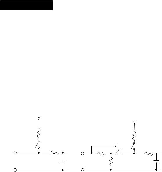
The following is a simplified schematic of both the UI-8-10 and the UI-8-10-10V Universal inputs:
Vref
|
|
Vref |
|
Rref |
|
|
Rref |
|
|
|
|
Swdis |
|
0-5V |
Swdis |
IN x |
|
Range |
|
IN x |
2.21K |
|
|
|
0-10V |
|
|
|
|
|
|
|
|
2.21K |
|
RET |
RET |
|
|
UI-8-10 |
|
UI-8-10-10V |
|
The main difference between the two is the UI-8-10-10V circuit includes a switch selectable front-end voltage divider that effectively divides the 10V input signal by two.
22 Andover Controls

UI-8-10
Each input includes a low-pass filter after the pull-up formed by a series resistor and a parallel capacitor. The resistor is utilized for over-voltage protection in limiting current to two protection diodes (not shown). Note also that all input returns are combined and must be directly connected to earth ground. It is possible to have more than one input share a single return wire. Keep in mind that the current through each input is approximately 0.3mA, so voltage drops occur with long runs of small gauge wire.
Pull-up Reference Resistor Selection Switches
In some measuring instances it is desirable that there be no pull-up resistor. Instead of physically removing or cutting the resistor off the printed circuit board, the input module includes a pull-up resistor selection switch (labeled Swdis in the diagram) for each input position. This switch allows you to select whether or not you want a pull-up resistor in the circuit. A small 8-position switch module is accessible from the front of the module when the door is opened.
Slide marker moves left and right
1 |
O |
2 |
N |
3 |
|
4 |
|
5 |
|
6 |
|
7 |
|
8 |
|
These switch modules are commonly called “DIP Switches” and require a small object such as the tip of a pen or a small screwdriver to operate them. Each switch position acts as a “slide switch”. Pressing the raised slide marker to the side marked “on” closes or enables the switch. To open or disable the switch position, press the slide marker over to the “off” side.
Continuum I/O System Reference 23

UI-8-10
Input Voltage Range Selection Switches (UI-8-10-10V Only)
The UI-8-10-10V module allows you to choose from two input voltage ranges. Selection is accomplished by using a switch arrangement that is similar to the operation of the pullup resistor switches. The Voltage Range switches allow you to select a range (0-5 V) or (0-10 V) for each input.
The 0-5V range allows connections to signals that do not exceed 5.00V. The 0-10V range allows connection to signals up to 10.00V. In this mode the circuit actually uses the same input measuring circuit as the 0-5V range, however, it divides the voltage present by two thereby limiting the internal circuitry to 0-5V. When you read a 0-10V input the actual reading will be 0-5V. You must adjust your readings for the higher range via formula.
Switching to 10V inputs dramatically lowers the impedance of the input to 4.4 KΩ.
This small 8-position switch module is located to the right of the pull-up selector switch and is accessible from the front of the module when the door is opened.
24 Andover Controls
 Loading...