


Controlling Tomorrow’s World
Infinity Smoke Control Guide
Electronic Version
Andover Controls Corporation i
Downloaded from - http://www.guardianalarms.net

Version B
Reproduction or dis tribution for bidden.
Copyright 1995, 1996 Andover Controls.
Subject to change without notice.
Order No. 30-3001-446
Copyright 1995, 1996
Andover Controls Corporation
300 Brickstone Square
Andover, Massachusetts 01810
All Rights Reserved.
Published by the Engineering Department at Andover Controls Corporation.
IMPORTANT NOTICE
Examples in this book are for illustrative purposes only and have never been tested in an
actual building.
This product is subject to change without notice. This document does not constitute any
warranty, express or implied. Andover Controls Corporation reserves the right to alter capabilities, performance, and presentation of this product at any time.
The following trademarks are used in this manual:
CROSSTALK is a registered trademark of Digital Communica tions Associates, Inc.
IBM is a registered trademark of Internati onal Busi ness Machines, Inc.
VT is a trademark of Digital Equipment Corporation.
ii Infinity Smoke Control Guide

Chapter 1
The Fundamentals of Smoke
Control
One of the most hazardous situations that you can face in a building is
smoke. While fires themselves are often damaging, it is smoke that can
cause the most injuries. For example, at the World Trade Towers in
February 1993, over 1,000 were injured by the smoke that resulted from
the fire.
TOC
To protect your building’s occupants, as well as furnishings and
equipment that may be damaged by smoke, you need a smoke control
system. A smoke control system, as its name implies, controls the flow
of smoke in your building in the event of fire. It keeps smoke from
spreading throughout the building, giving the building’s occupants a
clear evacuation route, as well as preventing further damage to the
building’s interior.
This chapter gives you an overview of smoke control theory.

The Fundementals of Smoke Con trol
Understanding Types of Smoke Control Systems
Two types of smoke control systems exist—dedicated and
nondedicated. The dedicated smoke control system is installed in a
building for the sole purpose of controlling smoke. A nondedicated
smoke cont ro l syst em uses parts of the building’s HVAC system to
control smoke.
In most instances, a building has both nondedicated and dedicated
systems. Nondedicated systems are used throughout the building for
normal areas (offices, manufacturing). Dedicated systems are used for
special areas, such as elevator shafts, stairtowers, and other areas that
need special smoke control techniques.
The operation of the nondedicated smoke control equipment is verified
by the “comfort level” in the areas that are served by the equipment. In
other words, if the HVAC equipment is not functioning properly, the
building’s occupants will be aware of this and the problem will get
fixed.
TOC
The operation of the dedicated smoke control equipment is verified by
an automatic self-test that is performed on a weekly basis.
1-2 Infinity Smoke Control Guide

The Fundementals of Smoke Control
Using Pressure to Control Smoke
The basic concept behind controlling smoke, r egardless of whether it is
with a dedicated or nondedicated system, is to use air pressure to confine
and (if possible) vent smoke from the building.
You cannot confine smoke by simply closing all access ways (such as
doors and vents) to the room that has the fire in it. Even with these
passages closed off, smoke can disperse throughout a building via
cracks, holes made for pipes and electrical wires, and spaces around
doors and windows. Smoke is driven through these small openings by
the expanding gases from the fire. Smoke can also be driven onto other
floors by the stack effect, which causes air to r ise in buildings. The stack
effect is caused by the difference in the interior and exterior temperature
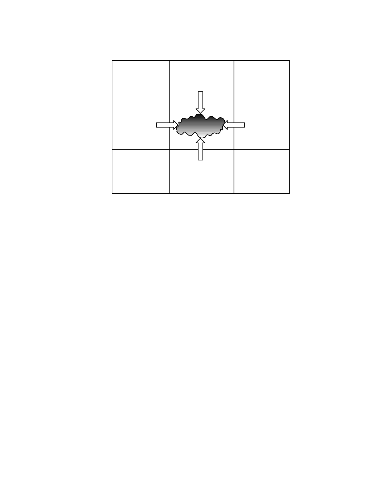
of the building. The following diagram shows how smoke can disperse
throughout a building.
TOC
Figure 1-1. Smoke Infiltrating Areas Adjacent to the Fire
Adjacent
Area
Adjacent Area
Area on Fire
Adjacent Area
Since smoke is carried by the movement of air, you can stop the spread
of smoke throughout the building by lowering the air pressure in the area
containing the fire and by raising the air pressure in the surrounding
areas and floors. The difference in pressure (also called the pressure
differential) between the smoke-filled area and the surrounding areas
acts as a barrier to the smoke, pushing i t back into the smoke-filled area.
The next illustration shows how this works.
Andover Controls Corporation 1-3
The Fundementals of Smoke Con trol
Figure 1-2. Air Pressure Containing Smoke
TOC
Positive
Air Pressure
Positive
Air Pressure
Positive
Air Pressure
Positive
Air Pressure
Negative Pressure
Positive
Air Pressure
Positive
Air Pressure
Positive
Air Pressure
Positive
Air Pressure
You lower the air pre ssure in the smoke-f illed area by shutting off all air
flow into it and turning on the exhaust fans from the area to full capacity.
This technique pulls the smoke out of the area and vents it outside of the
building.
You pressurize the areas and floors surrounding the fire by turning off
all exhaust systems (including closing any exhaust dampers) and forcing
supply air to those areas at f ull capacity. The air in the pressurized areas
tends to leak into the smoke zone, using the same cracks and holes that
the smoke would use to get out. This airflow into the burning room
keeps the smoke from spreading.
Areas that are neither being pressurized nor depressurized (i.e. areas far
away from the fire) have both their air inlets and air return systems
turned off. Turning off the air return prevents the smoke that is being
vented into the return air system from coming into the area.
In cases where there are large openings (such as an open doorway)
between the area on fire and an adjacent area, smoke can be confined by
a large volume of air. Pumping large amounts of air through the adjacent
space creates a constant draft through the opening into the smoke zone
(as shown in the next illustration). The draft through the open space
keeps back the smoke, confining it to the smoke zone. The amount of air
required to keep the smoke from penetrating the open space is quite
large, so you should avoid this sort of situation when possible.
1-4 Infinity Smoke Control Guide

The Fundementals of Smoke Control
Figure 1-3. Keeping Smoke Away from a Large Opening
TOC
Andover Controls Corporation 1-5

The Fundementals of Smoke Con trol
Creating Smoke Zones
In order to contain the smoke by using pressure, you must divide the
building into smoke control zones. A floor or several floors of the
building can be a single zone, or one floor can be br oken into a number
of zones. A zone must be separated from other zones by smoke dampers,
airtight doors, and smoke-proof barriers.
When a fire breaks out, the smoke control system can then pressurize all
of the zones around the one where the fire broke out (called the fire
zone), isolating the smoke to that single zone.
If the smoke control system is nondedicated, the layout of the smoke
control zones should take into consideration the layout of the HVAC
system. You should place multiple areas served by the same VAV boxes
in the same smoke control zone. Also, the smoke control zones must
conform to any fire control zones that have been established, because
the smoke detectors are tied into the fire detection system. Also, keeping
the smoke control zones and the fire control zones the same makes
coordinating the two systems simpler.
TOC
Smoke Control vs. Fire Control Systems
The smoke control system is usually separate from the fire control
system, since they have different goals. The fire control system’s goal is
to contain and extinguish the fire as fast as possible. These systems,
which halt the fire but not the smoke, are often triggered automatically,
relying on the heat of the fire to activate the system. Although smoke
control systems are also automatic, you must have manual overrides for
the automatic controls. Another difference between smoke control and
fire control systems is that where fire control systems, such as
sprinklers, often rely on only a water supply, smoke control systems
usually rely on electricity to run fans and dampers. So, some smoke
control systems have a standby power supply. Standby power provides
the smoke control system with electricity in case the main power fails.
The smoke control system should be designed to work with the fire
control system and not interfere with its operation. For instance, if the
building has a sprinkler system, then the smoke control system does not
need to control a large quantity of smoke, since the size of any fire
should be smaller.
1-6 Infinity Smoke Control Guide

The Fundementals of Smoke Control
A smoke control system may also have to be designed to work with
gas-based fire extinguishers, such as the halon gas systems installed in
many computer rooms. If the smoke contr ol system tried to vent a r oom
with such a system, it would probably vent the fire suppressing gas as
well. Removing the gas lets the fire continue burning. Also, pressurizing
the areas surrounding an extinguisher equipped room reduces the
effectiveness of the system as well. Air forced into the room from the
outside by pressure can provide the fire with the oxygen it needs to
continue burning. So, gas-based fire extinguishers and smoke control
systems should not be active at the same time in the same area.
The smoke control system receives the location of the fire from the fire
panel. The fire panel uses a combination of smoke and heat sensors to
determine where the fire is located.
In the event that signals are received from more than one smoke zone,
the smoke control system should continue automatic operation in the
mode determined by the first signal received.
TOC
Smoke control systems should never be triggered by manual pull boxes.
The risk of someone pulling a box someplace other than the fire zone is
too high for you to trust your smoke control system to this form of
activation.
All smoke control systems installed in buildings must meet the
standards established by the National Fire Protection Association in
their publication NFPA 92A, Smoke Control Systems, 1988 edition. You
can find additional information regarding fire alarm control units in the
Underwriters Laboratories Inc. Standard UL 864.
Andover Controls Corporation 1-7

The Fundementals of Smoke Con trol
Designing a Smoke Control System
What is the basic goal of the smoke control system? To maintain a
tenable environment. A tenable environment allows:
• The building’s occupants to evacuate safely
• The fire fighters to get to the fire zone
The first step you take in designing your smoke control system is to lay
out the smoke control zones, as previously explained. After the smoke
zones are established, you have to address the following design factors:
• The zone-by-zone smoke control strategies to use
• The amount of pressure needed to contain smoke
• Proper separation between zones
• The fans and ductwork used in the smoke control system
TOC
• Dampers required for smoke control
• The air inlets and outlets used in the smoke control system
• Duct smoke detectors
Devising a Smoke Control Strategy
For each zone in your building, you have to establish a smoke control
strategy. The smoke control strategy is a series of steps the smoke
control system must take to contain the smoke. For each zone, you must
decide:
• Whether you should depressurize the zone if a fire occurs.
• If the zone is to be depressurized, by how much you should
depressurize it.
• Which adjacent zones should be pressurized and how much pressure
is required.
Some zones in your building may need special consideration. As
mentioned earlier, zones that have gas fire extinguisher systems should
not be vented (depressurized) and the zones surrounding the fire zone
with such a system should not be pressurized. You may not be able to
pressurize other areas, such as hospital or animal labs, due to the risk of
contaminating surrounding areas.
Consider the number of zones surrounding the fire zone that should be
pressurized. While in theory, all you need to do is to pressurize all of the
1-8 Infinity Smoke Control Guide

The Fundementals of Smoke Control
zones immediately surrounding the fire zone, it is possible that smoke
can find its way around the pressurized areas and infiltrate zones far
away. Depending on the size of your building, and the capacity you plan
to have in the smoke control system, you may decide you want to
pressurize more than just the surrounding zones. But, the more zones
you want to pressurize, the larger your air supply system needs to be.
Write down the state that all fans, dampers, and other smoke control
equipment should be in to control smoke in each zone. Later, you have
to program this information into the smoke control system. This
information gives the smoke control system a strategy for containing
smoke in each possible fire zone.
TOC
Andover Controls Corporation 1-9

The Fundementals of Smoke Con trol
Determining the Amount of Pressure Needed
Since air pressure is what keeps smoke from spreading, the primary
design factors are the amount of pressure that you need to confine the
smoke and the size of the system used to create this pressure.
For the smoke control system to create a barrier of air pressure between
the smoke zone and surrounding zones, the amount of pressure required
varies with the height of the ceiling and whether or not the building has
a sprinkler system. The next table shows the minimum pressure
differential needed to keep smoke out of surrounding rooms.
Table 1-1. Minimum Pressure Differential to
Pressu rize Fir e Zone
TOC
Sprinkler
System
Yes Any 0.05
No 9 ft 0.10
No 15 ft 0.14
No 21 ft 0.18
Ceiling
Height
Minimum Pressure
Differential (wg)
For buildings without sprinklers and with ceiling heights not shown in
the table, you can use the following formula to determine the minimum
amount of pressure needed to keep smoke out:
1
MinimumPressure 7.64 H×
-----
T
1
----– SafetyFactor+×=
T
o
f
H is the distance between the fire space and a surrounding space where
2
the pressure differential is zero. A figure of the floor to ceiling height
--
3
is a conservative estimate.
To is the absolute room temperature of t he surrounding zones measured
in °R (degrees Rankine). Typically, To = 530° R (70° F). The conversion
from °R to °F is: °R = °F + 460.
Tf is the absolute temperature of the hot gases in the fire z one. It is a lso
measured in °R. Typically, Tf is 2160° R (1700° F).
1-10 Infinity Smoke Control Guide

The Fundementals of Smoke Control
SafetyFactor is a constant added to the results to make sure they are
sufficient. A value of 0.03 wg (inches water gauge) is recommended.
Pressure buildup in an area depends on how much leakage there is.
Leakage occurs through joints, cracks, openings for pipes and wires,
gaps between doors and their door jams, and so forth. The better the
zone is sealed off from its neighbors, the easier it is to maintain the
required pressure. Since larger openings, like doorways that are
normally open, require large amounts of air to maintain pressurization,
you should avoid this type of situation.
TOC
Andover Controls Corporation 1-11

The Fundementals of Smoke Con trol
Separating Zones
You must separate smoke zones from one another by smoke barriers,
which prevent smoke from passing through them. Smoke barriers can be
a wall, a floor, or a ceiling. Any openings in the smoke barrier must be
closed with a smoke-proof fitting. For example, all duct work going
through a smoke barrier must have a smoke damper in it. A smoke
damper is a damper that prevents smoke from passing through it when
fully closed. (Refer to the dampers section below for more information.)
During a smoke emergency all of the fittings should seal themselves, so
that smoke cannot penetrate the barrier.
Since the smoke control zones should be the same as the fire control
zones, you usually separate your zones with a fire ra ted partition. A fire
rated partition is a wall that is built of fire resistant materials and that
reaches from floor to ceiling. Different floors should be separated by a
fire rated ceiling, a ceiling made of fire resistant materia ls . Both fire
rated partitions and fire rated ceilings are rated for the amount of time
they can withstand a fire. Any openings in a fire rated partition or c eiling
must be sealable with a fire rated closure, such as fire rated doors or fire
damper.
TOC
Selecting Dampers
The dampers used to isolate the smoke zone must be smoke dampers.
Smoke dampers are dampers that meet the requirements given in UL
555S, Standard for Leakage Rated Dampers for Use in Smoke Control
Systems. Following this standard ensures that the dampers are able to
block the smoke when they are fully closed. These dampers may be
different from those you might use in an HVAC system that does not
perform smoke control.
In a smoke control system, the dampers must be able to travel to their
desired setting in 75 seconds. All dampers must be fitted with end
position microswitches to provide feedback to the smoke control
system. These switches let the control system know the position of the
dampers, since smoke dampers are usually either fully closed or fully
open.
Dampers sometimes function as both smoke dampers and fire dampers.
Fire dampers are dampers that block a fire from penetrating a fire rated
partition via a duct. These dampers are normally open, held in place by
a fus ible link. The f usible link is a heat-sensitive device that releases the
1-12 Infinity Smoke Control Guide

The Fundementals of Smoke Control
dampers when it is heated to a certain temperature. Once the fusible link
releases, the dampers close by the force of gravity. So, fire dampers
operate even if the electricity has failed. The specif ications for fire
dampers appear in the document UL555, Standard for Fire Dampers.
If you want a damper to function as both a smoke damper and a fire
damper, it must meet the requirements for both devices. These dampers
can be operated by electric motors or pneumatics. But it must, however,
also have a fusible link or other means of closing automatically, like a
regular fire damper. The control system can override the closure due to
temperature. The damper needs the fusible link in case the automatic
control of the damper by the control system is interrupted.
Choosing Fans and Duct Work
The fans and duct work used in the smoke control system must be
capable of providing the amount of pressure you calculated earlier. In a
nondedicated system, this may mean that you need to install fans that
have a higher capacity than the HVAC system calls for. The ducts must
be capable of taking the pressurization (or the depressurization, for the
fire zone’s return duct) that the smoke control system will exert.
TOC
Both the fans and the ducts should meet the requirements stated in
NFPA 90A, Standard for the Installation of Air Conditioning and
Ventilating Systems.
Fans for a smoke control system normally do not have to meet any
special heat resistance rating. In a smoke control system, fans must be
able to reach the required setting in 60 seconds. Each fan must have a
pressure monitor mounted so that the smoke control system can receive
feedback on the status of the fan to determine whether it is actually
operating or not.
In some climates, the outside air can be so cold that drawing it directly
inside the building can damage the building’s interior (freeze pipes or
damage temperature-sensitive equipment, for example). In these cases,
some sort of preheater needs to be installed on the air inlet. The smoke
control system does not have to control the heater as closely as one in an
HVAC system, since maintaining comfort levels is not an issue. It
simply has to make sure the air sent into an area is not going to damage
the building’s interior.
Andover Controls Corporation 1-13

The Fundementals of Smoke Con trol
Positioning Air Inlets and Outlets
You need to carefully consider the placement of the air inlets and outlets
on your building. If you place an outlet that vents smoke too close to an
air inlet, the air intake can draw the smoke back into the building.
Since smoke rises, the exhausts that vent smoke should be placed well
above air inlets. The exhausts should be placed at least 3 ft above the
roof level, to allow space for the smoke to rise and disperse.
Keeping smoke outlets far away from air inlets does not guarantee that
the air brought into the building is always smoke free. You may want to
place smoke detectors in air inlets that operate during a smoke
emergency. If the detector finds smoke in the incoming air, it alerts the
control system. The control system has to decide whether or not to shut
down the air inlet.
TOC
You should refer to NFPA 90A for more information on smoke
detectors in inlets and outlets.
1-14 Infinity Smoke Control Guide
The Fundementals of Smoke Control
Employing Dedicated Smoke Control Systems
Most of the systems discussed so far have been nondedicated systems.
Even in a building whose primary smoke control system is
nondedicated, you may have special zones or functions where you need
to use a dedicated system. The most common dedicated system is a
dedicated smoke control system for a stairtower.
StairTowers
Stairtowers are stairwells with a ventilation system and are isolated
from the main building. The only connection between the building and
the stairtower is fire-rated doors on each floor. Since the building’s
occupants should use the stairtower to leave during an evacuation,
keeping the stairtower smoke free is vital.
TOC
A stairtower has its own dedicated system that pressurizes the stairwell
to keep smoke out. This dedicated system can take several forms, from
a fan mounted in the roof of the stairtower, to a duct system that delivers
air to each level.
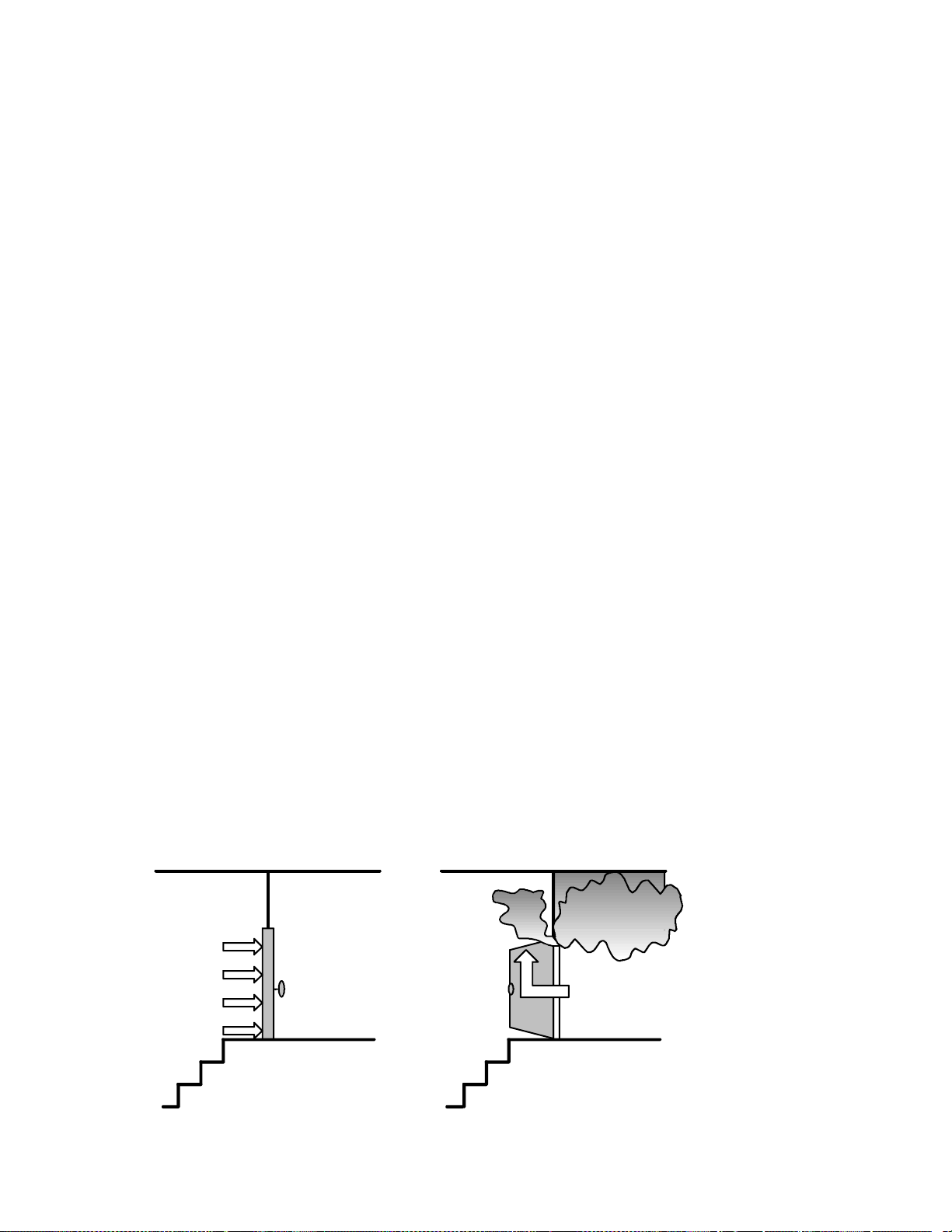
You must pressurize a stairtower enough to keep smoke out. However,
if the pressure in the stairtower is too great, then opening the doors
leading into the stairtower can be difficult. You must strike a balance.
The stairtower smoke control system must pressurize the stairway
enough to keep the smoke out, but it must not pressurize it so much that
the doors cannot be opened.
Figure 1-4. The Effects of Too Much and Too Little Pressure
Too Much Pressure
Too Little Pressure
Stairtower BuildingStairtower Building
Andover Controls Corporation 1-15
The Fundementals of Smoke Con trol
TOC
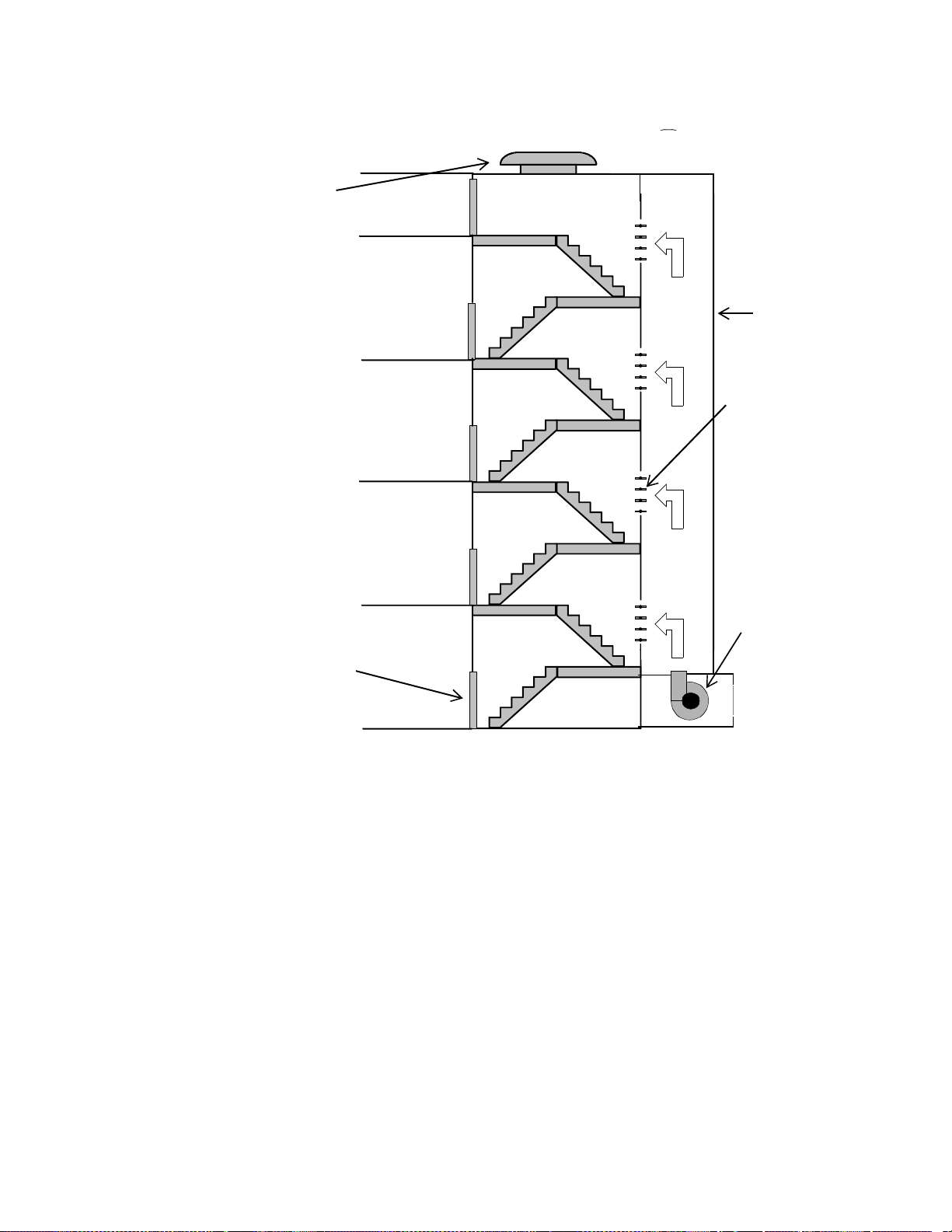
Figure 1-5. Parts of a Stairtower System
Exhaust Fan
or Vent
Air
Supply
Duct
Pressure
Vents
Fire Rated Door
Supply Fan
StairtowerBuilding
1-16 Infinity Smoke Control Guide

The Fundementals of Smoke Control
Ensuring Doors Can Be Opened
The table below shows the maximum allowable pressure differential
across a door in inches water gauge based on how wide the door is and
how much force the automatic door closing mechanism exerts. At the
pressures shown in the table, the door requires 30 lbf (pound of force) to
open, the maximum limit suggested by the NFPA Life Safety Code.
Table 1-2. Pressure Differential Across Doors
TOC
Door Closer
Force (lbf)
6 0.45 0.40 0.37 0.34 0.31
8 0.41 0.37 0.34 0.31 0.28
10 0.37 0.34 0.30 0.28 0.26
12 0.34 0.30 0.27 0.25 0.23
14 0.30 0.27 0.24 0.22 0.21
Pressure Differential for Various
Door Widt h s (inches)
32 in 36 in 40 in 44 in 48 in
The table above assumes a door height of 7 ft and a distance from the
doorknob to the knob side of the door of 3 in. If your door does not meet
these requirements, or has opening hardware other than a doorknob,
such as panic hardware, then refer to the ASHRAE publication Design
of Smoke Control Systems for Buildings for a formula to calculate the
proper opening force. The door widths in the table are only valid for
doors that are hinged at one end. For other types of doors, see the
ASHRAE document.
Many door closers vary the amount of force as the door opens. They
provide less resistance in the early stages of opening t he door than they
do later, when the door is almost fully open. The force to open the door
shown in the previous table represents the force needed to open the door
only enough to let air flow through the opening. Once air is able to flow,
the force exerted by the difference in air pressure on the door lessens.
Therefore, when calculating the force required to open the door, you
may need to lower the door closer force.
Andover Controls Corporation 1-17
The Fundementals of Smoke Con trol
Controlling Pressure in a Stairtower
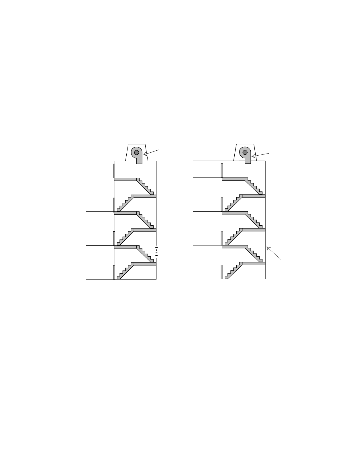
Stairtower smoke control systems are divided into two categories—
noncompensated and compensated. Noncompensated systems simply
turn on a fan to pressurize the stairtower. The fan’s speed does not
change to compensate for doors opening and closing. The more doors
that are open, the more the pressure differential between the stairwe ll
and the building drops.
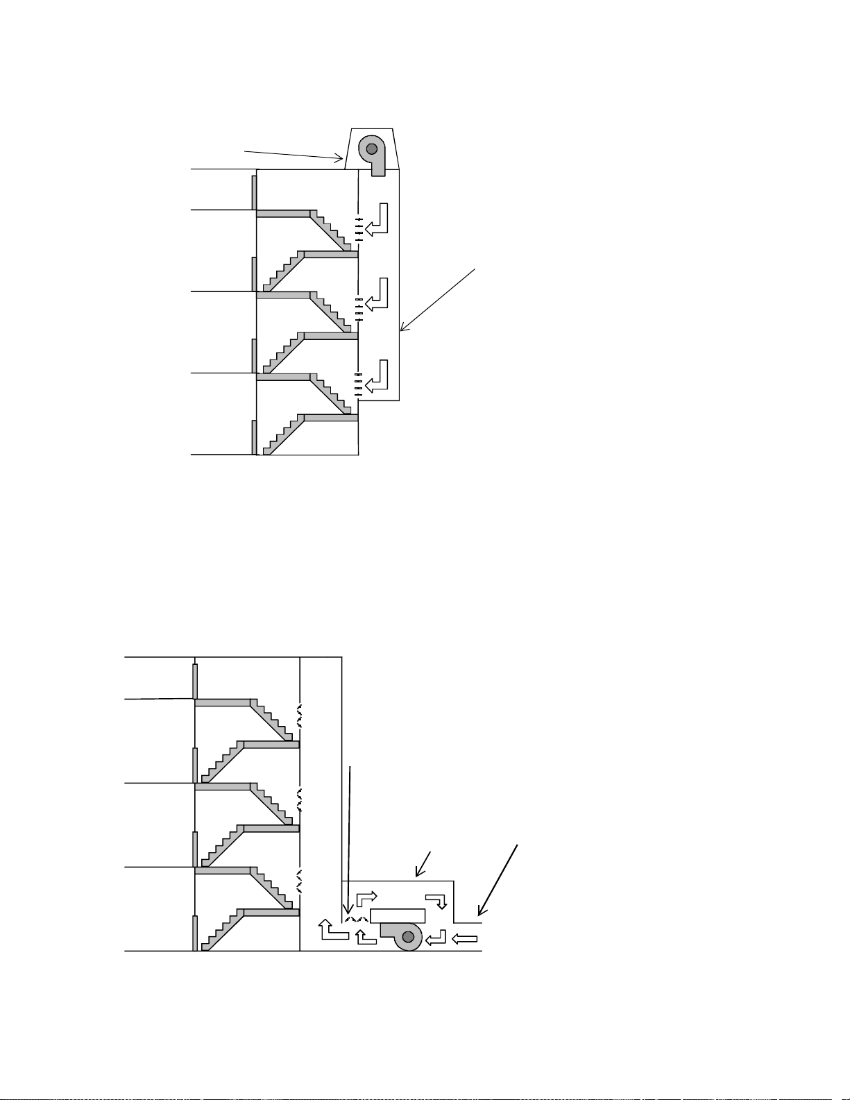
Figure 1-6. Compensated and Noncompensated Stairtower
Systems
Constant
Speed
Fan
VariableSpeed
Fan
TOC
Vent
A compensated system adjusts the airflow to make up for pressure lost
through open doors. It can use dampers to relieve excess pressure in the
stairtower to ensure that the pressure does not go over the maximum
limit.
There are a number of ways compensated stairtower smoke control
systems can control pressurization. In a basic system with a roofmounted fan blowing air into the stairtower, pressure can be regulat ed by
varying the speed of the fan, the pitch of the fan’s blade, the inl et vanes,
or the number of fans operating (assuming there is more than one).
More sophisticated systems use ducts to deliver air to several points in
the stairtower. The dampers can be controlled to maintain the
appropriate pressure in their zone.
1-18 Infinity Smoke Control Guide
The Fundementals of Smoke Control
TOC
Figure 1-7. Examples of Controlling Stairtower Pressure
Pressurizati o n Fan
Air Pressure
Duct
Duct systems can also use bypass dampers and ducts to control the
amount of air flowing from the fan to the outlets. The bypass dampers
are opened when the stairtower is at the proper pressure, so that excess
air flows not into the duct system, but into the bypass duct and back to
the air inlet. See the next diagram for an example of a bypass duct
system.
Figure 1-8. A Bypass Pressure Control System
Bypass Duct Dampers
Bypa ss Duct
Air Intake
Andover Controls Corporation 1-19

The Fundementals of Smoke Con trol
There are also a number of ways a compensated stairtower smoke control
system can get rid of excess air pressure, to ensure that the doors leading into
the stairtower can open properly. One or more vents to the building’s
exterior (with dampers) can be used in the stairtower to release excess
pressure. These dampers can be barometrically controlled (being forced
open by the excess air pressure) or controlled by electric motors or
pneumatics as in conventional HVAC systems. In both cases, the dampers
must be placed far enough away from the air s upply to prevent venting of
air that has not yet been able to disperse through the stairtower. Vents can
also lead into the building, but you should consider carefully the impact of
venting extra pressure into the building before using this type of vent.
In some cases, a ground-level stairtower door can be used in place of
dampers. This door automatically opens and closes to maintain the
proper amount of pressure in the stairtower. The door is usually locked,
for security reasons. During an emergency, the smoke control system
has to be able to override the lock. Using a door in this manner has its
problems, since wind effects close to the base of a building could
prevent the air from escaping through the door.
TOC
Figure 1-9. Methods of Controlling Stairtower Pressure
Roof-mounted Exhaust Fan
Vent to Outside with Barometrically
or Automatically Controlled Dampers
Automatic Door Used to Vent Pressure
You can al so use an exhaust fan to vent th e excess pressure f r om t he
stairtower. Such a f an should be d esigned to op er ate only when th e
stairtower is overpressurized. It should never be on when the pressure
differential between t he building and the s tairtower i s below the lowest
limit.
1-20 Infinity Smoke Control Guide

The Fundementals of Smoke Control
Elevators
Elevator shafts present a special menace with regards to smoke control.
The elevator shafts form perfect chimneys to draw smoke into the upper
levels of a building. Since elevators usually have openings on each floor,
and the seals on the elevator doors are often poor, the elevator shaft can
become a mechanism to spread smoke throughout a building. Smoke
control in an elevator shaft is an important consideration in the overall
smoke control plan.
Figure 1-10. Smoke Control For Elevator Shafts
Low Pressure Area
Created by Elevator
TOC
Speci a l Smoke
Proof Elevator
Doors
Low Pressure Area
Created by Elevator
Pressurization Fan
for Elevator Shaft
If you could manage to make them safe during smoke emergencies,
elevators would ease the evacuation of the building, especially for
people in wheelchairs. To have the elevators usable during a smoke
emergency, you need to pressurize the elevator shafts the same way you
pressurize a stairtower.
However, pressurizing the elevator shaft presents a number of problems.
While the elevator doors can be fitted with improved seals and rubber
sweeps, these systems will no t totally e liminate air leakage. Also, most
elevator shafts are not designed to be pressurized. They often have large
openings at the top where the cables feed into the winding room. Shafts
are often constructed of porous material that cannot contain the air
pressure. And since most shafts are not designed to be inspected after the
elevators are installed, finding and repairing cracks that would let smoke
infiltrate or pressure esc ap e is difficult.
Andover Controls Corporation 1-21

The Fundementals of Smoke Con trol
Another primary problem with letting elevators run during a smoke
emergency is the localized pressure differences that the cars create as
they travel up and down the shafts. For example, a car moving down
from the top of the shaft may create a small low air pressure zone near
the shaft’s top, which can pull smoke from the fire zone into the shaft.
At the present time , these issues have not be en resolved. Pressur izing the
elevator shafts so that the elevators can operate during a smoke
emergency is still being studied. In general, elevators should not be used
as an escape route during an evacuation.
TOC
1-22 Infinity Smoke Control Guide

The Fundementals of Smoke Control
Detecting Smoke
The fire control system is the system that is connected to the smoke and
fire detectors. Every smoke zone should have a Listed smoke and fire
detector installed in it. The detectors should be located so that they will
detect the presence of smoke or fire before it spreads beyond the zone.
Once the fire control system detects the fire, it relays to the smoke
control system the zone and the type of alarm that was triggered. The
smoke control system then takes action.
Never use manual pull stations to start the smoke control system. There
is no guarantee that the person pulling the alarm is in the same smoke
zone as the fire. The automatic smoke control system should take only
those actions that are common to all smoke strategies when a manual
pull station is activated. For example, the stairwell can be pressurized in
response to a manual pull box alarm. Implementing a specific smoke
control strategy must wait until the smoke detectors locate the fire zone.
TOC
Configuring and Mon itoring a S moke Control
System
The smoke control system should be able to act on its own in response
to detecting smoke. When it detects smoke, the system enacts the
strategy you planned out (as discussed in the design section of this
article). The automatic smoke control should stick with the strategy to
control smoke in the first zone that smoke is detected in. It would be
difficult for you to create strategies for controlling smoke in all possible
combination of zones.
The automatic smoke control system must have the highest priority over
all other automatic control systems in the building. It must override
energy management, occupancy schedules, or other controls. The
smoke emergency will probably last only several hours, so the impact
on energy management should be minimal. The only systems that
should be able to automatically override the smoke control system are
such safety systems as high pressure limiters.
Considering how unpredictable smoke is, you must have a manual
control panel from which the smoke control system can be monitored
and overridden. This panel, called a Firefighter’s Smoke Control Station
(FSCS), allows firefighting personnel to take manual control of the
smoke control system.
Andover Controls Corporation 1-23

The Fundementals of Smoke Con trol
Firefighter’s Smoke Control Station
The Firefighter’s Smoke Control Station (FSCS) is a graphic
annunciating control panel that gives firefighters information about the
state of the smoke control system as well as manual control over all of
its components. The FSCS should be located in a secure room or cabinet
to prevent unauthorized personnel from tampering with it. The room or
cabinet should be clearly marked so that firefighters can quickly locate
the FSCS.
The Fireman’s Smoke Control Station panel has a diagram of the
building showing the entire smoke control system, along with status
lights and override switches for all of the system’s components. The
diagram of the building should include all smoke control zones, all of
the ducts leading to and from the zones with arrows indicating the
direction of air flow in the ducts, and a clear indication of which zone
each piece of equipment serves.
TOC
The panel must have controls to activate all fans, dampers, and other
equipment related to the smoke control system. These manual controls
must be able to override all automatic control of smoke control
equipment. In particular, the FSCS must be able to override:
• Hand/off/auto switches
• Local start/stop switches on fan motor controllers
• Freeze detection devices
• Duct smoke detectors
The FSCS must not override such safety controls as:
• Electrical overload protection
• Maintenance personnel’s electrical disconnects
• High limit pressure switches
• Any fire/smoke damper thermal control as required by UL33
(standard for heat responsive links for fire protection service), heat
responsive links, or UL555S (the standard used for leakage rated
dampers for use in smoke control systems).
In non-dedicated systems, local motor controller’s hand/off/auto
switches can remain in-circuit with the FSCS panel. But, they can
remain in-circuit only if the switches are in a locked room accessible
only to authorized personnel. Also, if such a switch is thrown, a trouble
alarm must sound in the building’s main control center.
1-24 Infinity Smoke Control Guide

The Fundementals of Smoke Control
The indicator lights on the FSCS provide information about the
functioning of the system. The following colors should be used for the
FSCS indicators:
• Green—Fans and other equipment are running or dampers are open.
• Yellow—Dampers are in the closed position.
• Orange or Amber—The equipment has failed.
• Red—A fire has been detected in the area.
The FSCS has a lamp te st button that turns on all t he panel’s li ghts. Use
this button regularly to make sure none of the lights has burned out.
The FSCS gets information on the status of the smoke control system’s
equipment from proof monitors on the equipment itself. Each fan that
has a capacity over 2,000 cfm capacity should be mounted with a
pressure monitor. Smoke dampers should be fitted with end-range
microswitches to indicate that they are fully opened or fully closed.
TOC
All of the failure lights on the FSCS (the orange or amber ones)
represent the state of the equipment as determined by the proof sensors.
The failure light comes on if the piece of equipment is not in the state its
control is set for within its trouble indication time. This time is 60
seconds for a fan and 75 seconds for a damper. If, within that time, the
proof sensors do not report that the piece of equipment has responded to
the control system’s command, the FSCS indicates that the piece of
equipment has failed.
Andover Controls Corporation 1-25

The Fundementals of Smoke Con trol
Testing the System
During the installation, you should perform operational tests that make
sure the components and subsystems of the smoke control system are
installed correctly. After the installation is done, you must perform
acceptance tests, to prove that the smoke control system is capable of
doing what it was designed to do. The testing procedures are covered in
a later chapter of this manual.
Bibliography
The National Fire Prot ection As sociation. NFP A 90A, Standard for the
Installation of Air Conditioning and Ventilating Systems. The National
Fire Protection Association.
The National Fire Protection Association. 1988. NFPA 92A,
Recommended Practices for Smoke Control Systems. The National Fire
Protection Association.
TOC
Underwriters Laboratories, Inc. UL 555S, Standard for Leakage Rated
Dampers for Use in Smoke Control Systems. Underwriters Laboratories,
Inc.
Underwriters Laboratories, Inc. UL 555, Fire Dampers. Underwriters
Laboratories, Inc.
Underwriters Laboratories, Inc. UL 864, Control Units for Fire-
Protective Signaling Systems. Underwriters Laboratories, Inc.
1-26 Infinity Smoke Control Guide

Chapter 2
Infi nity Smoke Contr o l
System Components
This chapter presents a general overview of the Infinity smoke control
system and describes the UL listed system components used, the
features of each component, and their role within the system. The
following components are described:
• CX9200 main controller
• SCX920S controller
TOC
• TCX840 series controllers
• TCX850 series controllers
• TCX860/865 series controllers
• EnergyLink 2500 repeater
• InfiLink 200 repeater
• InfiLink 210 repeater
• FSCS (Firefighter’s Smoke Control Station)
• Fire Panel
Infinity Smoke Control System Components
Smoke Control System Overview
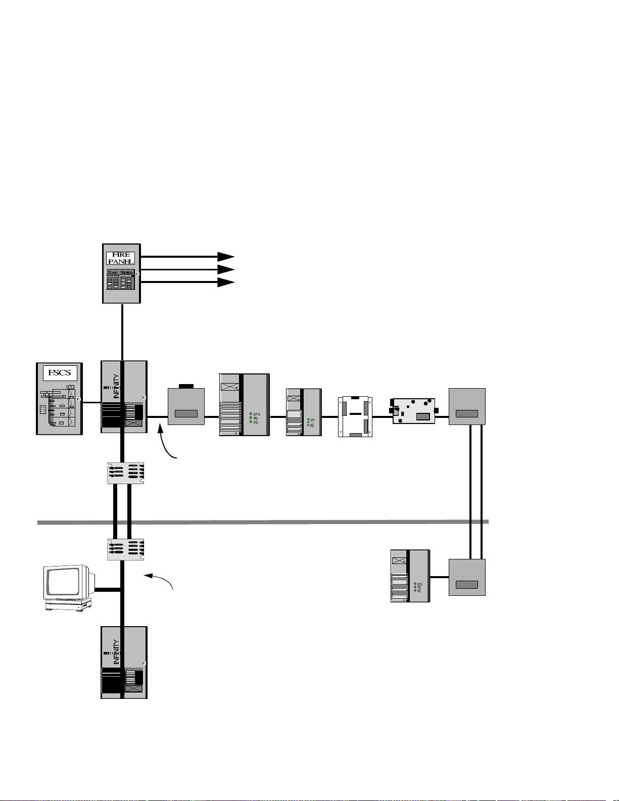
Figure 2-1 shows the components that are used in an Infinity smoke
control system and how they are connected together. The component
descriptions in the re mai nder of this chapter describe in more detail the
role of each component in the system. Notice that the smoke control
system itself is electricall y isol ated from the non-smoke control
components.
Figure 2-1. Smoke Control System Overview
Smoke Detectors,
Fire Detectors,
Manual Pull Boxes,
Etc.
TOC
RS-232
Cable
RS-232
Cable
fiber opti c
cable
SX8000
Workstation
CX9200
Infilink
200
Infi n et Cable
EnergyLink 2500
EnergyNet
Cable
SCX920S
UL Listed Smoke C ont rol Compon ents
Non-Sm oke Contr ol C omponent s
TCX 850
series series
TCX 840
series
TCX 860/5
fiber optic
cable
Infilink
210
2-2 Infinity Smoke Control Guide

Infinity Smoke Control System Components
CX9200 Controller
The CX9200 serves as the central controller in the Infinity smoke
control system. It controls the communication between the other system
components within the smoke control system. The C X9200 can be used
in a dedicated or a non-dedicated smoke control application. The
CX9200 connects to other controllers in the following ways:
• The CX9200 connects to other CX9200 controllers via the E nergyNet
network.
• The CX9200 connects to the Infinet controlle rs, such as the SCX920S,
the TCX850 series, TCX 840 series, or the TCX860/865 series, via
the Infinet network.
• The CX9200 also connects to both the FSCS and Fire panel using 2
RS-232 ports.
TOC
When the CX9200 is utilized for smoke control, it performs the
following functions:
• Initializes the smoke control system.
• Receives fire alarms from the Fire Panel and instructs the Infinet
controllers to execute a smoke control strategy.
• Reads the manual override settings and updates the LEDs and alarm
on the FSCS.
• Performs weekly self-tests on all the dedicated components in the
smoke control system.
• Monitors the controllers in the smoke control system and signals the
FSCS when there is a communication fault or output override.
Features
• Plain English programming language
•1 Energynet communications port
• 3 RS-232/RS-485 communications ports
• 1 RS-232/RS-485/RS-422 communications port
• Supports up to 254 Infinet controllers
• Battery backup: 1 hour full UPS to 72 hours for memory only
• 115V/230V AC power input
• DCX250 touch-screen display option
• 9600 bps Infinity Modem option
• ENL2500 Energynet repeater option
Andover Controls Corporation 2-3

Infinity Smoke Control System Components
SCX920S Controller
The SCX920S controller is used to control a large piece of equipment,
such an AHU (Air Handling Unit), or several smaller pieces of
equipment, such as smoke dampers. The SCX920S communicates with
the CX9200, as well as other Infinet controllers, via the Infinet network.
The SCX920S can be used in a dedicated or a non-dedicated smoke
control application.
Features
• Plain English programming language
• 16 Universal inputs that can be configured to measure Voltage,
Current, Temperature, or Digital (contact closure) values
• 8 Outputs that can be either FormC relay contacts, Voltage outputs,
or Current outputs
TOC
• 1 RS-485 Infinet port
• Lithium battery backup for memory and Real Time Clock
• 24V/115V/230V AC power input
• Available in either an open class plastic housing, designed to be
placed in a Listed enclosure, or as a fully enclosed unit with a locking
door
• Optional Local Display/Keypad option
2-4 Infinity Smoke Control Guide

Infinity Smoke Control System Components
TCX840 Series Controllers
The TCX840 series includes the TCX840, TCX843, TCX845, TCX846
controllers. The TCX840 series controlle rs are used to control small
pieces of equipment that require fewer I/O points than an SCX920S,
such as VAV boxes or stairwell fans. The TCX840 series communicates
with the CX9200, as well as other Infinet controllers, via the Infinet
network. The TCX840 series can be used in a dedicated or a nondedicated smoke control application.
Features
• Plain English programming language
• Universal inputs that can be configured to measure Voltage, Current,
Temperature, or Digital (contact closure) values
TOC
• Analog outputs can be either voltage or current
• Air-flow sensor that measures differential pressure
• 1 RS-485 Infinet port
• Lithium battery backup for memory
• 24V AC power input
Table 2-1 lists the I nput/Output capabiliti es of each of the controlle rs in
the TCX840 series.
Table 2-1. TCX840 series I/O capabilities
TCX840 TCX843 TCX845 TCX846
Universal Inputs
Form A Outputs
Tri-State Outputs
Analog Outputs
0 - 1" Air-flow Sensors
2244
2555
1222
0022
1101
Andover Controls Corporation 2-5

Infinity Smoke Control System Components
TCX850 Series Controllers
The TCX850 series includes the TCX850, TCX851, TCX852, TCX853,
and TCX855 controllers. The TCX850 series controllers are used to
control small pieces of equipment that require fewer I/O points than an
SCX920S, such as VAV boxes or stairwell fans. The TCX850 series
communicates with the CX9200, as well as other Infinet controllers, via
the Infinet network. The TCX850 series can be used in a dedicated or a
non-dedicated smoke control application.
Features
• Plain English programming language
• Universal inputs that can be configured to measure Voltage, Current,
Temperature, or Digital (contact closure) values
• Air-flow sensors that measure di ffer enti al pressu r e
TOC
• 1 RS-485 Infinet port
• Lithium battery backup for memory
• 24V AC power input
Table 2-1 lists the Input/Output capabilities of each of the controllers in
the TCX850 series .
Table 2-1. TCX850 series I/O capabilities
TCX850 TCX851 TCX852 TCX853 TCX855
Universal Inputs
Form A Outputs
Tri-State Outputs
0 - 1" Air-flow Sensors
0 - 0.2" Air-flow Sensors
44264
33133
11111
10120
00001
2-6 Infinity Smoke Control Guide

Infinity Smoke Control System Components
TCX860 Series Controllers
The TCX860 series includes the TCX860, TCX861, TCX862, and
TCX863 controllers. Like the TCX850 series, the TCX860 series
controllers are used to control VAV boxes. The TCX860 series
communicates with the CX9200, as well as other Infinet controllers, via
the Infinet network. The TCX860 series can be used in a dedicated or a
non-dedicated smoke control application.
The TCX860 series controllers have a built-in motor and gear assembly
for direct control of a damper.
Features
• Plain English programming language
• Universal inputs that can be configured to measure Voltage, Current,
Temperature, or Digital (contact closure) values
TOC
• Analog outputs can be either Voltage or Current
• Air-flow sensors that measure differential pressure from 0 to 1 inches
water gauge
• One RS-485 Infinet port
• Lithium battery backup for memory
• 24 V AC power input
Table 2-2 lists the I nput/Output capa bilities of each of the controlle rs in
the TCX860 series.
Table 2-2. TCX860 Series I/O Capabilities
Input/Output Types TCX 860 TCX 861 TCX 862 TCX 863
Universal Inputs
Form A Outputs
Analog Outputs
Airflow Sensors
4424
3333
—222
1111
Damper Motor
EMX170 ports
Powerfail PCB
Andover Controls Corporation 2-7
111—
—111
——1 —

Infinity Smoke Control System Components
TCX865 Series Controllers
The TCX865 series includes the TCX865, TCX866, TCX867, TCX868 and
TCX869 controllers. Like the TCX860 series, the TCX865 series controllers are
used to control VAV boxes. The TCX865 series communicates with the
CX9200, as well as other Infinet controllers, via the Infinet network. The
TCX865 series can be used in a dedicated or a non-dedicated smoke control
application.
The TCX865 series controllers have a built-in motor and gear assembly for
direct control of a damper.
Features
• Plain English programming language
• Universal inputs that can be configured to measure Voltage, Temperature, or
Digital (contact closure) values
TOC
• Analog outputs can be either Voltage or Current
• Air-flow sensors that measure differential pressure from 0 to 1 inches water
gauge
• One RS-485 Infinet port
• Lithium battery backup for memory
• 24 V AC power input
Table 2-1 lists the Input/Output capabilities of each of the controllers in the
TCX865 series.
Table 2-1. TCX865 Series I/O Capabilities
Input/Output Types TCX 865 TCX 866 TCX 867 TCX868 TCX 869
Universal Inputs
Form A Outputs
Analog Outputs
Airflow Sensors
22222
33033
00002
11111
Damper Motor
Sensor ports
Real Time Clock
2-8 Infinity Smoke Control Guide
111 —
00011
01011

Infinity Smoke Control System Components
EnergyLink 2500
The EnergyLink 2500 is an active network hub for the EnergyNet
network that has slots for plugging in various media interface modules.
The EnergyLink 2500 can perform the following functions:
• Allows the Energynet to be used in a star configuration
• Extends the length of an Energynet network
• Connects different Energynet media types together
• Allows for electrical isolation on an Energynet network by using fiber optics.
Features
• Slots for up to 7 media interface modules
TOC
• Mounts inside the CX9200 cabinet
• Power (+5V DC) supplied by the CX9200 power supply
Table 2-3 lists the 3 different media interface modules that are available
for the EnergyLink 2500.
Table 2-3. EnergyLink 2500 Media Interface Modules
Media Type Media Interface Module
Twi s te d Pair (10 BASE-T) ENL2501
Thin Coaxial (10BASE-2) ENL2502
Fiber Optic (10BASE-FL) ENL2503
Andover Controls Corporation 2-9

Infinity Smoke Control System Components
Infilink 200
The InfiLin k 200 is a repeater and network expander for the Infinet
network.
The InfiLink 200 can perform the following functions:
• Amplify an RS-485 Infinet signal, thus allowing for extension
beyond 4,000 feet
• Expand an RS-485 Infinet signal into 4 more RS-485 channels, thus
allowing for up to 127 Infinet controllers on a network
• Convert an RS-485 signal into an RS-232 signal
Features
• 5 RS-485 ports
TOC
• 1 RS-232 port
• Switch selectable baud rates
• Enclosure is standard
• 115V/230V AC power input
2-10 Infinity Smoke Control Guide

Infinity Smoke Control System Components
Infilink 210
The InfiLi nk 210 is a fiber optic repeater for the Infinet network. The
InfiLink 210 is used to convert a single RS-485 Infinet signal into 2 fiber
optic Infinet channels. Therefore, if an Infilink 210 is used at each Infinet
controller, the entire network can use fiber optics. The Infilink 210 can
be used to electrically isolate one section of the Infinet network from
another section.
Features
• 1 RS-485 port
• 2 fiber optic ports. Each port has a Receive Data connection and a
Transmit Data connection.
• Switch selectable baud rates
• Enclosure is standard
TOC
• 115V/230V AC power input
Andover Controls Corporation 2-11

Infinity Smoke Control System Components
The FSCS
The Firefighter’s Smoke Control Station (FSCS) is a custom panel that
provides full monitoring and manual control capability over all smoke
control equipment. In the event of an emergency, it is used by the fire
department to override the smoke control system.
Features
The FSCS should contain a building diagram that clearly indicates the
type and location of all smoke control equipment, and the areas served
by the equipment (smoke control zones). Since the FSCS uses a
graphical depiction of the building, each FSCS will be unique and must
be custom made.
The FSCS graphic must show all fans in excess of 2000 CFM, all
dampers or groups of VAV boxes, and all major ducts and how the ducts
are connected together. The FSCS graphic must provide a clear
indication of the direction of airflow in the ducts.
TOC
If the FSCS graphic is t oo la rge to fit on a single panel, multiple pane ls
may be used.
Manual Overrides
The FSCS must provide manual controls that will override any piece of
equipment in the smoke control system. The FSCS must have the
highest priority in the smoke control system. The FSCS must be able to
override any other manual or automatic control that is being used in the
system, except when these controls are intended to protect against
electrical overloads, provide for personal safety, or prevent major
system damage. VAV boxes that are all located within and serve one
designated smoke control zone may be controlled collectively.
Fans require a 3-position control that provides ON-AUTO-OFF
capabilities. Dampers require a 3-position control that provides OPENAUTO-CLOSE capabilities. The AUTO position is removed if the
override is for a piece of equipment that can only be controlled by the
FSCS.
In addition to the controls mentioned above, you can also have a 3position control for each zone that provides PRESSURIZE-AUTOEXHAUST capabilities.
2-12 Infinity Smoke Control Guide

Infinity Smoke Control System Components
Status Indicators
The actual status of the smoke control equipment must be clearly
indicated on the FSCS by the use of visual indicators with appropriate
legends.
Fans must have a single indicator that turns on when the fan’s
differential pressure “proof sensor” indicates that the fan is operating.
Dampers must have 2 indicators: one that turns on when the damper’s
end-limit “proof sensor” indicates that the damper is closed , and one that
turns on when the damper’s other end-limi t “proof sensor” indicates that
the damper is open. Both indicators should be off when the damper is
positioned between the open and closed positions.
The FSCS should provide a status indicator for each zone that signals
whether or not the zone is in an alarm condition.
TOC
The FSCS should provide status indicators for each piece of equipment
that signals when there has been an equipment failure. For instance, if
the fans do not turn on within 60 seconds, or the dampers do not reach
the desired position within 75 seconds, the fault indicator should turn on.
Table 2-4 lists the status indicator colors that m ust be used on the FSCS
Table 2-4. FSCS Status Indicator colors
Status Color
Damper OPEN or Fan ON Green
Damper CLOSED Yellow
System or Equipment FAULT Amber/Orange
Zone ALARM Red
Andover Controls Corporation 2-13

Infinity Smoke Control System Components
Other Features
The FSCS will also have the following features:
• Master Key – This key will silence the audible alarm and enable all
of the controls on the FSCS. This key must be made available to
authorized personnel only.
• Clear Faults Button -- This momentary push-button will clear all of
the fault indicators on the FSCS. This push-button is not enabled
unless the Master key is ON. If the fault corrects itself, the fault
indicator will automatically turn off. If the fault returns, the fault
indicator will turn on again. If there is a fault detected during the
weekly self-test of a dedicated controller, the fault indicator for that
piece of equipment will stay on until it is cleared. The C lear Faults
push-button is wired to an input on the FSCS, just like any other
switch.
• Lamp Test Button - This momentary push-button turns on all of the
status indicators on the FSCS, thus allowing the operator to
determine if there is a bad indicator.
TOC
• Audible Alarm – The alarm sounds when there is a smoke emergency
or when there is an equipment fault. Turning the Master key ON is
the only way to silence the alarm.
Ordering Information
Andover Controls’ UL listing includes a custom FSCS panel that is
manufactured by Automation Displays Incorporated. For ordering
information, contact:
Automation Displays Inc.
3533 North White Avenue
Eau Claire, Wisconsin 54703
(715) 834-9595
2-14 Infinity Smoke Control Guide

Infinity Smoke Control System Components
Design Guidelines
In order to have the FSCS built to your specifications, you will need to
supply the following:
• An accurate drawing of the smoke control system. This drawing will
be used to create the FSCS front panel graphic.
• A second copy of the FSCS drawing indicating the colors of the
status indicators.
• A third copy of the FSCS drawing indicating the colors that are to be
used for the front panel graphic. Consult Automation Displays, Inc.
for a list of options.
• Specify whether you need a flush-mount or a surface-mount panel.
• Specify whether or not you need a transparent cover for the FSCS.
• Specify whether or not you need a terminal block wired to the FSCS
inputs, to be used for Zoned Wiring to the Fire Panel.
TOC
Automation Displays, Inc. will provide you with a copy of the FSCS
drawing that indicates the I/O numbers that correspond to each LED
output and each switch input on the FSCS. Each 2 position switch
requires 1 input and each 3 position switch requires 2 inputs.
The FSCS you order from Automation Displays Inc. will contain the
following:
• An Automation displays’ Autoface IV graphic door with a keylock.
• Switches and Status Indicators for each piece of smoke control
equipment.
• A “Master” keyswitch, a “Clear Faults” push-button, a “Lamp Test”
push-button and a sonalert audible annunciator.
• An Automation Displays’ Q-Card CPU board with the “Andover
Data Interface” firmware that is wired to an RS232 Protection PCB.
• An Automation Displays’ 80 Point Driver card for every 80 status
indicators.
• An Automation Displays’ 80 Point Driver card for reading the FSCS
switches. A 2 position switch requires 1 input and a 3 position switch
requires 2 inputs. A Switch Protection PCB is also included.
• A 5V DC power supply for the Q-Card, the 80 Point Driver cards,
and the FSCS Status Indicators.
Refer to Chapter 5 for a drawing of an example FSCS graphic.
Andover Controls Corporation 2-15

Infinity Smoke Control System Components
The Fire Panel
The Fire Panel connects to all of the smoke detectors, fire detectors,
manual pull boxes, fire alarms, etc. within the buil ding. When one of the
Fire Panel sensors detects a problem, the Fire Panel informs the Infinity
smoke control which sensor is in an alarm condition and what the alarm
condition is. The Infinity smoke control system receives all of it’s alarm
information from the Fire Panel. The smoke control zones must
correspond to the Fire Panel’s fire zones.
There are two methods for connecting the Fire Panel to the Infinity
smoke control system: using an RS-232 communications channel or by
the Zoned Wiring method.
RS-232 Communications
As part of Andover Controls’ UL Listing, the following Fire Panels can
communicate directly with the CX9200 via RS-232:
TOC
Simplex Time Recorder Co. Series 4100
1 Simplex Plaza
Gardner, Massachusetts 01441
(508) 632-2500
Edwards Systems Technology, Inc. Model # IRC-3
195 Farmington Avenue
Farmington, Connecticut 06032
(203) 678-0410
Zoned Wiring
If you are using a Fire Panel that is not listed above, you will have to
connect to the Infinity smoke control system using the Zoned Wiring
method. This requires running a set of wires for each zone from a contact
closure output on the Fire Panel to inputs on the FSCS. The CX9200 will
poll the FSCS to determine when a zone is in an alarm condition. If you
plan on using this method, you must specify that a terminal block be
provided with the FSCS that connects to the FSCS inputs. See the
following chapter for more details.
2-16 Infinity Smoke Control Guide

Chapter 3
Installation and Layout
This chapter gives instructions for installing and interconnecting the
Infinity smoke control system components.
All wiring in an Infinity smoke control system must comply with the
National Electric Code (NFPA 70), as well as any state or local
regulations.
Special requirements for using Infinity equipment to perform smoke
control is covered in detail in this chapter. For general installation
instructions, see the installation guides for each individual component.
These installation guides are shipped with the Infinity controllers.
Topics covered in this chapter are:
TOC
• Installing the CX9200
• Installing Infinet Controllers
— The SCX920S
— The TCX840 series
— The TCX850 series
—The TCX860/865 series
— The Infilink 200
— The Infilink 210
• Installing the FSCS
• Installing the Fire Panel

Installation and Layout
Installing the CX9200
For detailed information on how to mount and connect the wiring to the
CX9200 and it’s peripherals, refer to the following Andover Controls
documentation:
TOC
Infinity CX9200 Hardware Installation Guide
Energylink 2500 Installation Guide
DCX250 Installation Guide
Infinity Modem Guide
(P/N 30-3001-196)
(P/N 30-3001-404)
(P/N 30-3001-393)
(P/N 30-3001-347)
Cable Li m i ta tions
• The RS-232 cable between the CX9200 and the FSCS must be no
longer than 20 feet, and must be enclosed in conduit.
• The RS-232 cable between the CX9200 and the Fire Panel must be
no longer than 20 feet, and must be enclosed in conduit.
Comm Port Assignments
In a smoke control system, it is recommended that you use the following
Comm Port assignments:
• COMM1 – FSCS panel RS-232
•COMM2 – Infinet Network
• COMM3 – User terminal
• COMM4 – Fire Panel RS-232
Isolating Energynet Controllers
In a system that performs smoke control, the CX9200s have to be
electrically isolated from other Energynet devices using the Energylink
2500 and the ENL2503 fiber optic module. This is done in order to
ensure that a fault on one of these devices will not interfere with the
operation of the smoke control system. The Energylink 2500 is only
required when connecting CX9200s to other Energynet devices, it is not
required between CX9200s.
The Energylink 2500 mounts in the CX9200 cabinet and receives it’s
power from the CX9200 power supply.
Figure 3-1 shows the use of the Energylink 2500 to isolate the CX9200
from other Energynet controllers.
3-2 Infinity Smoke Control Guide

Installation and Layout
Figure 3-1. Isolating the CX9200
CX9200
CX9200
with
Energylink 2500
TOC
Energynet
Smoke Control Components
Fiber
Optics
Energynet
Other Energynet Components
Andover Controls Corporation 3-3

Installation and Layout
Installing Infinet Controllers
For detailed information on how to mount and connect the wiring to the
various Infinet controllers and repeaters, refer t o the following Andover
Controls documentation:
TOC
SCX920 Installation Guide
TCX840 Installation Guide
TCX850 Installation Guide
TCX860 Installation Guide
TCX865 Installation Guide
Infilink 200 Installation Guide
Infilink 210 Installation Guide
(P/N 30-3001-170)
(P/N 30-3001-493)
(P/N 30-3001-173)
(P/N 30-3001-390)
(P/N 30-3001-497)
(P/N 30-3001-178)
(P/N 30-3001-394)
Smoke Control Requirements
In addition to the information contained in each installation guide, the
following requirements apply when using the Infinet controllers and
repeaters in a smoke control system .
The SCX920S
• When using the SCX920S in a dedicated smoke control application,
the manual overrides must be disabled. The SCX920 installation
guide explains this process in detail.
• When using the SCX920S in a non-dedicated smoke control
application, you must do one of the following:
— Disable the manual overrides, or
— Locate the SCX920S in area only accessable to authorized
personnel, and provide an OVERRIDE status indicator on the
FSCS that turns on when the outputs are overridden. The FSCS
audible indicator must also turn on.
• If the AC input voltage is to be set to 24 V, an Andover Controls’
Listed transformer must be used to supply the 24V AC input power .
These transformers must be placed in a Listed enclosure and must be
wired according to the National Electric Code, as well as any state or
local regulations.
Table 3-1 lists the step-down transformers that are available from
Andover Controls.
3-4 Infinity Smoke Control Guide

Installation and Layout
The TCX840 and TCX 850 serie s
• Only an Andover Controls’ Listed transformer may be used to supply the 24V AC
input power for the TCX840 and TCX850 series. These transformers must be placed
in a Listed enclosure and must be wired according to the National Electric Code, as
well as any state or local regulations.
Table 3-1 lists the step-down transformers that are available from Andover Controls.
• All of the Input and Output wiring on the TCX840 and TCX850 series must remain in
the same room.
The TCX860/865 series
• Only an Andover Controls’ Listed transformer may be used to supply the 24V AC
input power for the TCX860/865 series. These transformers must be placed in a Listed enclosure and must be wired according to the National Electric Code, as well as
any state or local regulations.
TOC
Table 3-1 lists the step-down transformers that are available from Andover Controls.
Table 3-1. Listed 24V Step-down Transformers
Primary and
Voltage PRI:SEC VA Rating Part Number
115V : 24V 40 VA 01-2100-378 Solderless Lug
115V : 24V 40 VA 01-2100-323 Wires
277V : 24V 50 VA 01-2100-379 Solderless Lug
208/240V : 24V 40 VA 01-2100-407 Wires
Secondary
Connec t io ns
• All of the Input and Output wiring on the TCX860/865 series must remain in the s ame
room.
The Infilink 200
• Any cables connected to the RS-232 port must be less than 20 feet in length, and must
be enclosed in conduit.
The Infilink 210
• The Infilink 210 must be used to electrically isolate the Infinet controllers that are
performing smoke control from the non-smoke control Infinet controllers. This is
Andover Controls Corporation 3-5

CX9200
TOC
Installation and Layout
done in order to ensure that a fault on one of these devices will not
interfere with the operation of the smoke control system. The Infilink
210 is not required between every Infinet controller, it is only
required between groups of controllers that are performing smoke
control and groups of controllers not performing smoke control.
Figure 3-2 shows the use of the Infilink 210 to isolate the Infinet
smoke control components.
Figure 3-2. Isolating the Infinet Controllers
SCX920S
TCX840 series
TCX850 series
TCX860/865 series
Infilink 200
Smoke Control Components
Infilink
210
Fiber
Optics
Infilink
210
Infinet
Other Infinet Controllers
3-6 Infinity Smoke Control Guide

Installation and Layout
Installing the FSCS
For detailed information on how to mount the FSCS, refer to:
Automation Displays Inc.
3533 North White Avenue
Eau Claire, Wisconsin 54703
(715) 834-9595
Location and Access
The FSCS should be located close to the other fire fighter’s systems that
are in the building. Means should be provided to ensure only authorized
access to the FSCS. When acceptable to the authority having
jurisdiction, the FSCS should be located in a room that is separated from
public areas by a suitably marked and locked door. The location, room
size, access means, and other physical design considerations of the
FSCS location must be acceptable to the authority having jurisdiction.
TOC
Inside the FSCS
Figure 3-3 shows what the typical components inside an FSCS wil l look
like. Since the FSCS is custom made for each application, the internal
layout will vary from panel to panel.
Andover Controls Corporation 3-7

SWITCH
PROTECTION
PCB
TOC
Installation and Layout
Figure 3-3. Typical Internal Components in an FSCS
80 POINT LED DRIVER CARD
80 POINT SWITCH INPUT CARD
WIRING
TROUGH
+5V
+5V
COM
COM
12 3 4
Q-CARD PROCESSOR PCB
+5V DC POWER SUPPLY
ON
1 A
POWER SWITCH
AND LINE FUSE
RS-232
PROTECTIO N
PCB
OUT IN COM
RS-232 FIELD
WIRING TERMINALS
AC POWER
H
FIELD WIRING
N
TERMINALS
G
3-8 Infinity Smoke Control Guide

Installation and Layout
Field Wiring Te r m inals
The following are the only field connections that are required when
installing an FSCS. All field wiring must be installed by qualified
personnel and must comply with the National Electric Code, as well as
any state or local regulations.
AC Power Wiring
The AC input voltage is connected to the AC POWER FIELD WIRING
TERMINALS.
Figure 3-4 shows this terminal block and how it is wired.
Figure 3-4. AC Power Terminal Block
TOC
H
N
G
The HOT Terminal (Black wire)
The NEUTRA L Te rm inal (White w ire )
The GROUND Terminal (Green wire)
RS-232 Communication Port Wiring
The RS-232 cable from the CX9200 connects to the FSCS at the RS-232
FIELD WIRING TERMINALS. This cable must be less than 20 feet in
length, and must be enclosed in conduit.
Figure 3-5 shows this terminal block and how it is wired to the CX9200.
Andover Controls Corporation 3-9

Figure 3-5. RS-232 Terminal Block
RS-232
PROTECTION
PCB
OUT IN COM
TOC
Installation and Layout
COMMON
DATA IN
DATA OUT
Wire to pin 7 on the CX9200 RS-232 port
Wire to pin 2 on the CX9200 RS-232 port
Wire to pin 3 on the CX9200 RS-232 port
Zoned Alarm Contact Wiring (Optional)
As stated in the previous chapter, if you are not using a Fire Panel that
is part of the Andover Controls Listing, you will have to connect the Fire
Panel to the smoke control system using the Zoned Wiring method. This
involves connecting a set of wires for each zone from the Fire Panel to
the FSCS. Each contact closure output on the Fire Panel will be wired to
an input on the FSCS, which is read by the CX9200. These FSCS inputs
will be wired at a terminal block in the FSCS (not shown). This wiring
must be less than 20 feet in length, and must be enclosed in conduit.
The Q-Card Processor PCB
The Q-Card controls the RS-232 communications with the CX9200,
reads the FSCS switch inputs from the 80 Point Switch I nput cards, and
controls which Status Indicators will be turned on by the 80 Point LED
Driver cards.
The Q-Card has a Reset switch and an Options dipswitch. Pressing the
Reset switch re sets the pr ocessor, but maintains t he curre nt status of the
LEDs. The Options dipswitch is used to s et the RS-232 baud r ate and to
enable the auto-blanking feature. When the auto-blanking feature is on,
the status LEDs will be cleared if the FSCS does not receive any data
from the CX9200 within 10 seconds. The Q-Card only reads the Options
dipswitch after a Reset.
3-10 Infinity Smoke Control Guide

Installation and Layout
Table 3-2 shows the settings for the Options dipswitch..
Table 3-2. Q-Card Options Dipswitch Settings
Switch Position: 1234
Auto-blanking ON ON
Auto-blanking OFF OFF
9600 Baud OFF OFF OFF
7200 Baud OFF OFF ON
4800 Baud OFF ON OFF
3600 Baud OFF ON ON
2400 Baud ON OFF OFF
1200 Baud ON OFF ON
600 Baud ON ON OFF
TOC
300 Baud ON ON ON
Andover Controls recommends setting the FSCS for 9600 baud, with
auto-blanking disabled, therefore all the dipswitches are OFF.
Figure 3-6 shows the location of the switches on the Q-Card.
Figure 3-6. The Q-Card switch settings
Reset Switch Options Dipswitch
1 2 3 4
Q-CARD PROCES SOR PCB
Andover Controls Corporation 3-11

Installation and Layout
Installing the Fire Panel
Refer to the Fire Panel manufacturer’s documentation for installation
and wiring instructions.
The Fire Panel connects to the CX9200 through an RS-232 cable. This
cable should be no longer than 20 feet in length, and must be enclosed
in conduit.
Figure 3-7 shows how to wire the RS-232 cable from the Fire Panel to
the CX9200.
Figure 3-7. Fire Panel RS-232 Wiring
a. Simplex Model 4020
TOC
Port A
XMIT
RTS
RCV
CTS
GND
CX9200 DB-25
b. Edwards Systems Technology Model IRC-3
TB1
TXD
RXD
COMM
CX9200 DB-25
Pin 2 (TD)
Pin 3 (RD)
Pin 7 (GND)
Pin 2 (TD)
Pin 3 (RD)
Pin 7 (GND)
3-12 Infinity Smoke Control Guide

Chapter 4
Configuring the System
This chapter briefly describes how to configure the smoke control
system and how to communicate with the various smoke control system
components. For more detailed information concerning these and other
topics, refer to the following Andover Controls manual:
Infinity CX Programmer’s Guide (P/N 30-3001-166)
This chapter does not attempt to explain the system’s programming
language or how to write smoke control application programs. Refer to
Chapter 5 for example smoke control programs.
Topics covered in the chapter are:
TOC
• Logging On to the CX9200
• Using the Command Window
• Using the Menus
• Logging Off the CX9200
• Assigning Security Levels to Users
• Setting the System Date and Time
• Configuring the Commports
• Creating and Editing Points
• Creating and Editing Files

Configuring the Sys te m
Logging on to the CX9200
When you first power up the CX9200, COMM3 at 9600 baud is the
default communications port for your terminal. After connecting an R S232 cable between your terminal and COMM3, type WINDOW. You
will not see the word WINDOW on your terminal as you are typing.
The CX9200 will respond with the Infinity Window.
The Infinity Window prompts you for a User Name first. If the CX9200
has just been powered up or reset, you must type in the predefined User
Name ACC. Otherwise, type in your own User Name.
The Infinity Window then prompts you for a Password. If the CX9200
has just been powered up or reset, you must type in the predefined
Password ACC. Otherwise, type in your own Password.
If you logged in under the User Name ACC and Password ACC, you
are the system administrator and have full access t o the system. You
should change the Password ACC to another Password in order to
prevent unauthorized access to the system. For details , refer to the
section in this chapter on Assigning Security Levels to Users.
TOC
Figure 4-1 shows the Infinity Window.
Figur e 4-1. The Infinity Window
iewV ditE onnectC ogoutL
INFINI TY
(C) 1990 Andover Controls Corporation
Version 1.5
User Name
Password
ACC
4-2 Infinity Smoke Control Guide

Configuring the System
Using the Command Window
Once you have logged on to the CX9200, th e Command window will be
displayed. The Command window is the main window in the Infinity
system .
Along with the Command window, you will see the Main Me n u Bar at
the top of the screen and the StatusBar at the bottom.
Figure 4-2 shows the Command window.
Figure 4-2. The Command Window.
iewV ditE onnectC ogoutL
Command Window - INFINITY1
R>
TOC
The Main Menu Bar
The Main Menu Bar has selections for View, Edit, Connect and
Logout. The current selection will be highlighted. The View and Edit
selections will cause a Pulldown Menu to appear. The Main Menu Bar
selections will be discussed in more detail throughout this chapter.
The Command Window
The Command window allows you to enter commands directly to the
smoke control system. You enter these commands at the Command
Andover Controls Corporation 4-3

Configuring the Sys te m
window’s R> prompt. You toggle between the Main Menu Bar and the
Command window using the F4 key.
You can print the values of System Variables, Start and Stop Programs,
or execute many other commands from the Command window. For
example, if you type the following:
R>PRINT DATE
The CX9200 will respond by printing the Date and Time inside the
Command window.
The StatusBar
The StatusBar can be used by a program to Print any information that is
available in the Infinity syste m .
TOC
4-4 Infinity Smoke Control Guide

Configuring the System
Using the Menus
Although many of the Infinity Menus look different, they all respond to
the same set of keystrokes. This section summarizes some of these
keystrokes.
You change between the Main Men u Bar selections using the LEFT and
RIGHT ARROW keys. In order to accept a selection, you can either
press ENTER while the selection is highlighted, or enter the first letter
of the selection.
You change between selections in a pulldown menu using the UP and
DOWN ARROW keys. In order to accept a selection, you can either
press ENTER while the selection is highlighted, or enter the first letter
of the selection.
Once in another menu, you use the TAB key to change from attri bute to
attribute. To go to the previous attr ibute, hit the ES C key, then the T AB
key.
TOC
If an attribute uses a small window and has a list of selections that have
a set of parentheses before them, use the UP and DOWN ARROWS to
change between the selections, and use the SPACE bar to accept a
selection. After you accept the selection, an X will appear in the
parentheses.
When the system is prompting you to enter a name, you can press the F2
key to get a list of the available choices.
The F4 key allows you to toggle between the Menu Bars and the
Windows.
Logging Off the CX9200
In order to Log Off the CX9200, simply se lect the Logout selection from
the Main Menu Bar.
After Logging Off the CX9200, it will not respond t o anything you type
on the terminal. You must perform the Logging On procedure if you
want to communicate with the CX9200 again.
Andover Controls Corporation 4-5

Configuring the Sys te m
Assigning Security Levels to Users
This section describes how to assign new Users for the Infinity system
and how to set the Passwords and Security Levels for these Users.
Starting at the Main Menu Bar, select the Edit function. A pulldown
menu will appear showing what Edit functions are available. Select the
Users option from the pulldown menu.
Figure 4-3 shows the Edit pulldown menu.
Figure 4-3. Edit pulldown menu
TOC
iewV ditE onnectC ogoutL
R>
Edit
Command Window - INFINITY1
Users
Points
Files
Commports
Controllers
Infinet Controllers
System Date & Time
System Variables
Persons
Areas
Doors
After selecting Edit Users, you will be prompted to enter the User
Name. Type in the Name of the User that you want to add or change and
hit ENTER. For example, if you want to change the Password of the
initial predefined use r, enter ACC. You may also use the F2 key to view
the selections that are available to you.
The User Window will now appear on the screen. The User Window
allows you to enter the Password, set the Security Level, and enter other
information about this User.
4-6 Infinity Smoke Control Guide

Configuring the System
When you want to select a particular security level, hit the SPACE bar
and an (X) will appear to the left of the selection. When you are done
editing this User, TAB over to the Save box and hit ENTER. This new
User information will now be entered into the system.
Figure 4-4 shows the User Window.
Figure 4-4. The User Window
iewV ditE onnectC ogoutL
Command Window - INFINITY1
User - INFINITY1 ACC
TOC
User Name
Full Name
Password
Login Program
Logout Program
ACC
ACC
Security Level
( ) No Access
( ) View Only
( ) Acknowledge Alarms
( ) Change Values
( ) Enable/Disable
( ) Configure
( ) Program
(X) Administrate
SAVE
SAVE AS
CANCEL
DELETE
TEACH
Andover Controls Corporation 4-7

Configuring the Sys te m
Setting the System Date and Time
Starting at the Main Menu Bar, select the Edit function. A pulldown
menu will appear showing you the Edit functions that are available.
Figure 4-3 shows the Edit pulldown menu.
Select the System Date & Time option from the pulldown menu. The
System Time window, which allows you to set the date and time, will
now appear on the screen. Enter the date and time in the same format
that appears in the window. When the date and time are set, TAB to the
OK box and hit ENTER. You have now set the date and time throughout
the Infinity system.
Figure 4-5 shows the System Time window.
Figure 4-5. The System Time Window
TOC
iewV ditE onnectC ogoutL
Command Window - INFINITY1
R>
System Time - INFINITY1
Date and Time
March 24 1994 15:20:00
OK
CANCEL
4-8 Infinity Smoke Control Guide

Configuring the System
Configuring the Commports
The CX9200 has four Communication Ports that must be configured for
use with the smoke control system. In a smoke control system, it is
recommended that you assign the Commports as follows:
• COM M1 - RS-232 port for the FSCS
•COMM2 - Infinet Network
• COMM3 - User Terminal
• COM M4 - RS-232 port for the Fire Panel
Configuring COMM1 for the FSCS
Starting at the Main Menu Bar, select the Edit function. A pulldown
menu will appear showing you the Edit functions that are available.
Figure 4-3 shows the Edit pulldown menu.
TOC
Select the Commports option from the pulldown menu. After selecting
Edit Commp orts, you will be pr ompted to enter the Commport Na me.
You can either type in COMM1, or press the F2 key for a list of the
available selections. After entering COMM1, press the ENTER key and
the Commport window will appear on the screen.
The Commport window allows you to enter a description, set the Default
Mode, and set the Baud rate. For use with the FSCS, the Commport
should be set up as follows:
• Description = F SCS In t erf ace (for example)
• DefaultMode = Printer
• Baud rate = Baud9600
Once the information has been entered, TAB to the SAVE box and hit
the ENTER key. Comm1 has now been configured.
Figure 4-6 shows the Commport window.
Andover Controls Corporation 4-9

Configuring the Sys te m
Figure 4-6. The Commport Window
iewV ditE onnectC ogoutL
Command Window - INFINITY1
Commport - INFINITY1 COMM1
TOC
Name
DefaultMode
Mode
COMM1
(X) Printer
( ) Window
( ) Command
( ) Infinet
( ) Lbus
( ) Autoset
( ) TankNet
( ) Xdriver
Printer
Description
Baud
( ) Baud300
( ) Baud1200
( ) Baud2400
( ) Baud4800
(X) Baud9600
( ) Baud19200
FSCS Interface
SAVE
CANCEL
Configuring COMM2 for Infinet
Select Edit Commports and enter COMM2 at the Name prompt. When
the Commport window comes up, set the DefaultMode attribute to
Infinet.
When you hit the TAB key the Commport window will change slightly
and two more boxes will appear that are labeled Learn and View. These
new selections apply to an Infinet port. The Learn box in st r u ct s t h e
CX9200 to poll the Infinet Network and bring any available controllers
On-line. The View box instructs the CX9200 to print out the status of the
Infinet controllers.
The attributes should be set as follows:
• Description = Infinet Port (for example)
• DefaultMode = Infinet
• Baud rate = Baud19200
Once the attributes are set properly, TAB to the Learn box and hit
ENTER. Th e CX9200 will respond with a window that says Learn
Mode is Active.
4-10 Infinity Smoke Control Guide

Configuring the System
When the CX9200 has completed polling the Infinet Network, it will
display the Infinet Summary window. This window shows the name,
port, model, serial number and status of all of the Infinet devices.
Figure 4-7 shows an example of the Infinet Summary window.
Figure 4-7. The Infinet Summary window
iewV ditE onnectC ogoutL
Infinet Summary - INFINITY1
Name Model Serial Number ID StatusPort
920 80858 1 OnlineCOMM2lc_0080858
920 80857 2 OnlineCOMM2lc_0080857
853 63078 3 OnlineCOMM2lc_0063078
TOC
The F4 key will bring you back to the Commport window. Use the UP
ARROW key to go to the SAVE box and hit the ENTER key. The
CX9200 will display the Command window. COMM2 has now been
configured for Infinet.
If this is the first Learn you have performed on this Infinet Network, the
CX9200 will assign a name to each controller that is based on it’s serial
number and port. You can change these names to something more
meaningful, such as AHU1 or FLOOR2_TCX, by going to the Edit
pulldown menu, selecting Infinet Controllers, pressing the F2 key to
list the available choices, and selecting the Infinet controller name that
you would like to change.
The CX9200 will display the Infinet Controller window. You can now
change the name of the Infinet controller. You can also add a
Description for this Infinet controller, such as Floor 1 Air Handling
Andover Controls Corporation 4-11

Configuring the Sys te m
Unit. When you have done this, TAB to the Save box and hit the
ENTER key. The CX9200 will return to the Command window.
Figure 4-8 shows the Infinet Controller window.
Figure 4-8. The Infinet Controller Window
iewV ditE onne c tC ogoutL
Command Window - INFINITY1
Infinet Controller - INFINITY1 AHU1
TOC
Name
Model
Description
Infinet ID
Serial Number
Error Time
Error Count
AHU1
920
Floor 1 Air Handling Unit
COMM2
Port
1
80858
Error
0
Version
Status
Reconfigs
SAVE
1.5
SAVE AS
CANCEL
OnLine
DELETE
RESET
0
From the Ma in Me n u Ba r , you can select View, then Infinet
Controllers to verify your name changes and to view the status of all of
the Infinet cont rollers.
Configuring COMM3 for the Users Terminal
The default settings are as follows:
• DefaultMode = Autoset
• Baud rate = Baud9600
• TerminalType = VT100
If you need to change any of these settings, or you want to enter a
description, you select Edit Commports and use COMM3 as the name.
4-12 Infinity Smoke Control Guide

Configuring the System
Configuring COMM4 for the Fire Panel
This section describes how to configure COMM4 to communicate with
the Fire Panel. The CX9200 communicates with the Fire Panel using a
piece of software called an Xdriver, which is available from Andover
Controls. Instead of selecting Edit Commports from the Main Menu
Bar to configure COMM4, you load an Xdriver “.dmp” file into the
CX9200 using a computer that is running a communications program.
Each Fire Panel will have it’s own unique Xdriver. If you are using a
Simplex Fire Panel, you will need the SPX Xdriver. If you are using an
Edwards Systems Technology Fire Panel, you will need the EST
Xdriver.
Loading an Xdriver
You should receive four files in your Xdriver package, one for each
commport. Since COMM4 is being used for the Fire Panel, you will
either use the spxcom4.dmp Xdriver for a Simplex panel, or the
estcom4.dmp Xdriver for an Edwards Systems Technology panel. The
Xdriver loading procedure is as follows:
TOC
• If your CX9200 controller name is not “INFINITY1”, then you must
edit the Xdriver file and change all occurrences of “INFINITY1’’ to
your controller name.
• If your CX9200 Energynet ID is not “1”, then you must change the
number at the end of the line “Dictionary : CONTROLLER NAME
: 1” to your controller’s Energynet ID.
• Go to the Command window on the CX9200 and type load -o-m at
the R> prompt and hit the ENTER key.
• From your computer, send the appropriate Xdriver “.dmp” file.
• When the reload is done, the CX9200 will return to the Command
window. Type print COMM4 xdriverstatus at the R> prompt and
the CX9200 should respond with “Installed”.
See the section titled Creating and Editing Points for instructions on
how to create variables that use the Xdriver port.
Andover Controls Corporation 4-13

Configuring the Sys te m
Creating and Editing Points
This section explains how to create and edit a Point. A point refers to a
variable that is us ed by the Infinity system. For example, a Point can be
an input on a controller, an output on a controller, a numeric variable, a
character string, or an Xdriver variable.
Creating an Input/Output Point
Select Edit Points from the Main Menu Bar. Enter the name of the
Infinet controller at the InfinetCtlr prompt. Enter the name of the Point
at the Name prompt. If it is a new Point, you will have to type in the
name that you wish to give the Point, such as:
OADmp for the Outside Air Damper output
Sfan for the Supply Fan output
TOC
If you are editing an existing Point, you can hit the F2 key at the Name
prompt and get a list of the available choices.
After entering the Point Name , the Point window will appear. The Point
window allows you to define the attributes of this Point. You must set
the Type of Point, such as Input or Output. You must set the Electrical
Type for an Input/Output Point, such as Voltage, Digital, Current, or
TriState. You must set the Channel Number for each Input/Output
Point. The Ch annel Number refers to the physical Input or Output
number on the Infinet controller. Each Infinet controller will have
different Input/Output capabilitie s. Refe r to Chapte r 2 for an
explanation of each controller.
If you select the DETAILS box, you can enter a Description of the
Point, enter the Display Format f or a Point, or define other attributes of
the Point.
When you are done entering the attributes, TAB to the SAVE box in the
Point window and hit the ENTER key. The CX9200 will return you to
the Command window.
Figure 4-9 shows an example of a Point window.
4-14 Infinity Smoke Control Guide

Configuring the System
Figure 4-9. Example Point Window
iewV ditE onnectC ogoutL
Command Window - INFINITY1
Point - INFINITY1 AHU1 Sfan
TOC
Name
Type
( ) Input
(X) Output
( ) Numeric
( ) Dat eTim e
State
( ) Disabled
(X) Enabled
Sfan
=
Channel Number
Electric al Type
( ) Voltage
(X) Digital
( ) Current
( ) TriState
( ) Pneumatic
( ) ReaderDoor
( ) HiResVoltage
( ) HiResCurrent
1
SAVE AS
Creating a Numeric Point
A Numeric Point is a variable that can be used by the Infinity system . A
Numeric Point is created the same way as an Input or Output point.
When you call up the Point window, set the Type to Numeric. A
Numeric Point does not have selections for Channel Number or
Electrical Type because they do not apply. You can select the
DETAILS box in order to enter a description for the point.
SAVE
CANCEL
DETAILS
Creating an Xdriver Point
An Xdriver Point is a variable that will be used by the CX9200 to get
alarm and status information from the Fire Panel. In order to create an
Xdriver Point, create a Numeric Point and select the DETAILS1 box.
A window will appear on the screen prompting you to enter a Port. Enter
COMM4 for the Port because that is the Port that the Fire Panel is
connected to. Press the TAB key (not ENTER) after typing in COMM4
and some additional fields will appear on the screen. The number of
fields and the name of the fields will be different for different Xdrivers.
These fields correspond to the physical Fire Panel sensor numbers that
Andover Controls Corporation 4-15

Configuring the Sys te m
this Xdriver Point is to represent. Refer to your Fire Panel
manufacturer’s documentation for a description of these fields.
Figure 4-10 shows the Simplex Xdriver fields.
Figure 4-10. Simplex Xdriver Fields
iewV ditE onnectC ogoutL
Point - INFINITY1 Smoke.SPX
COMM4
Port
SAVE
TOC
Card
Point
Sub-Point
Status/Time
CANCEL
Figure 4-11 shows the Edwards Systems Technology fields.
4-16 Infinity Smoke Control Guide

Configuring the System
Figure 4-11. EST Xdriver Fields
iewV ditE onnectC ogoutL
Point - INFINITY1 Smoke.EST
COMM4
Port
Loop
Address
TOC
SAVE
CANCEL
Refer to Appendix A for a list of the possible Xdriver values that can be
received from the Fire Panel, and what Events they correspond to.
Andover Controls Corporation 4-17

Configuring the Sys te m
Creating and Editing Files
This section briefly explains how to create and edit a File. A File can be
a Program, a Function, a Data file or a Report. These Programs, which
run in the CX9200 and in the Infinet controllers, determine how the
Infinity smoke control system operates.
The Programs are written in Andover Controls’ Plain-English language.
It is beyond the scope of this manual to explain the Plain-English
language or how to write Programs. Refer to the following Andover
Controls documentation for Plain-English programming instructions:
TOC
Plain English Language Reference
Infinity CX Programmer’s Guide (P/N 30-3001-166)
(P/N 30-3001-165)
Creating a Program
Select Edit Files from the Main Menu Bar. If the Program will be
running in an Infinet controller, enter the name of the Infinet controller
at the InfinetCtlr prompt. If the Program will be running in the CX9200,
leave the InfinetCtlr prompt blank. Enter the name of the Program at the
Name prompt. If it is a new Program, you will have to type in the name
that you wish to give the Program, such as:
SmokeSelfTest
FSCS_Interface
If you are editing an existing Program, you can hit the F2 key at the
Name prompt and get a list of the available choices.
After entering the Program Name, the File window will appear. The File
window allows you to enter a Description for the Program or define the
attributes of the Program, such as State, Flowtype or whether or not the
Program should start automatically.
Figure 4-12 shows the File window.
4-18 Infinity Smoke Control Guide

Configuring the System
Figure 4-12. The File Window
iewV ditE onnectC ogoutL
Command Window - INFINITY1
File - INFINITY1 SmokeSelfTest
TOC
Filename
Type
(X) Program
( ) Function
( ) Data
( ) Report
SmokeSelfTest
Description
State
FlowTyp e
( ) AutoStart
(X) Command Line
Weekly Dedicated System Tests
( ) Disable d
(X) Enabled
CANCEL
( ) Looping
(X) FallThru
After entering the information into the File window, TAB to the SAVE
box and hit the ENTER key. The CX9200 will now bring up the Editor
window. The Editor window allows you to create a new Program or edit
an existing Program.
SAVE
DELETE
DETAILS
When you are editing a File, the File Menu Bar is at the top of the screen.
The File Menu Bar has pulldown menus that allow you to use the Editor.
Hit the F4 key to toggle between the Editor window and the File Menu
Bar.
When you are finished editing your program, select the File pulldown
menu from the File Menu Bar, then select the Save option. The CX9200
will now compile and save your program. The compiler will alert you i f
there are any errors in the program.
If you configured the Program for AutoStart, it will begin to run after it
is compiled and saved. If not, you can Start or Stop the Program from
the Command window, or from another Program.
To exit the Editor and r etu rn to the Command window, select File Quit
from the File Menu Bar.
Andover Controls Corporation 4-19

Configuring the Sys te m
Figure 4-13 shows the Editor window, the File Menu Bar, and part of a
sample program.
Figure 4-13. The Editor
TOC
File
Begin_prog:
‘Clear Self - Tes t Fa ults
AH3Sfan.ST.Fail = Off
FL2SADmp.ST.Fail = Off
FL2RADmp.ST.Fail = Off
FL3SADmp.ST.Fail = Off
FL3RADmp.ST.Fail = Off
FL4SADmp.ST.Fail = Off
FL4RADmp.ST.Fail = Off
RunTests:
Print “ RUNNING DEDICATED SELF-TEST “ to COMM3 StatusBar
CloseDampers:
SMKDMPRS DefaultDmprPosn = On
WaitForDampers:
If TS < (MaxDamperTime + 5) then Goto WaitForDampers
ditE
INFINITY1 - SmokeSelfTest
earchS heckC
oolsT
Functions, Data files and Reports are created the same way as a
Program.
The File Menu Bar
• The File pulldown menu allows you to Open a File, Save a File,
modify the Configuration of a File, set the Firing Order of a File,
or Quit the Editor and return to the Command window.
•The Edit pulldown menu allows you to Cut, Copy, Paste, Clear,
and Select text within the Editor.
• The Search pulldown menu allows you to Find text, find and
Replace text, or search for the Next Error or the Previous Error.
•The Check selection will check for errors in your File.
• The Tools pulldown menu will allow you to view a Point Summary,
a File Summary, a Program Summary, a System Variable
Summary, or the Message window. It will also allow you to Edit a
Point, Edit a System Variable, or create a split screen that contains
the Com mand Windo w on the top of the screen and the Editor on
the bottom half.
4-20 Infinity Smoke Control Guide

Smoke Control Programs
Chapter 5
Smoke Control Programs
This chapter describes some example Infinity smoke control programs.
These example programs are for illustrative purposes only. Since each
system is unique, your programs will not be identical to these examples,
but the same principles will apply.
The HVAC example programs were included to show how the smoke
control mode must have priority over the HVAC modes. The HVAC
programs do not perform any HVAC functions.
These programs are written in Andover Controls’ Plain-English
language. It is beyond the scope of this manual to explain the Plain-
English language or how to write applications programs. Refer to the
following Andover Controls documentation for Plain-English
programming instructions:
TOC
Plain English Language Reference
Infinity CX Programmer’s Guide (P/N 30-3001-166)
Topics covered in this chapter are:
• Example Smoke Control System
• CX9200 Programs
— Programs for Communicating with the FSCS
— Programs for Verifying Equipment Operation
— Programs for Smoke Control
— Programs for Controlling the System
• Controlling the Smoke Dampers
• Controlling the Air Handling Units
• Controlling the Stairwell Fan
• Controlling the VAV Terminals
(P/N 30-3001-165)
5-1 Infinity Smoke Control Guide

Smoke Control Programs
Example Smoke Control System
Figure 5-1 shows a block diagram of the smoke control components that
could be used to create a smoke control system for a small, four story
building. This example system will be used as the basis for the programs
in this chapter.
Figure 5-1. Example Smoke Control System
TCX853
AHU-3
Stairwell
TOC
SCX920S
AHU-2
Floors 2-4
SCX920S
Smoke
Dampers
Floors 2-4
SCX920S
AHU-1
Floor 1
TCX861
VAV Terminal
Floor 4
TCX851
VAV Terminal
Floor 3
TCX840
VAV Terminal
Floor 2
INFINET
RS-485
Firefighter’s Smoke
Control Station
5-2 Infinity Smoke Control Guide
CX9200
Main Controller
RS-232RS-232
Fire Panel
Simplex or EST

Figure 5-2 shows the FSCS graphic for the example system.
Figure 5-2. Example FSCS
TOC
Smoke Control Programs
Firefighter’s Smoke Control Station
AHU-2 SUPPLY FAN
STAT US FAIL
AUTO
AHU-2
AHU-2 OA DAMPER
FAIL
OPEN
OPEN
AHU-2 EX DAMPER
OPEN
OPEN
AHU-2 CONTROLLER
FLOORS 2 - 4
FAULT OVERRIDE
AHU-1 CONTROLLER
FAULT OVERRIDE FAULT OVERRIDE
SMOKE DAMPER
CONTROLLER
FAULT OVERRIDE FAULT OVERRIDE
AHU-3 STAIRWELL
CONTROLLER
FAULT OVERRIDE
CLEAR
FAULTS
AUTO
FAIL
AUTO
FLOOR 1
CLOSED
CLOSED
CLOSED
CLOSED
LAMP TEST
FAULT OVERRIDE
ON
AHU-2 RA DAMPER
FAIL
OPEN
AUTO
OPEN
AHU-2 RETURN FAN
STATUS FAIL
ON
FLOOR 4
VAV CONTROLLERS
FLOOR 3
VAV CONTROLLERS
FLOOR 2
VAV CONTROLLERS
MASTER
KEY
SONALERT
AUTO
OFF
CLOSED
CLOSED
OFF
SA SMOKE DAMPER
FAIL
OPEN
OPEN
RA SMOKE DAMPER
OPEN
OPEN
SA SMOKE DAMPER
OPEN
OPEN
RA SMOKE DAMPER
OPEN
OPEN
SA SMOKE DAMPER
OPEN
OPEN
RA SMOKE DAMPER
OPEN
OPEN
AUTO
FAIL
AUTO
FAIL
AUTO
FAIL
AUTO
FAIL
AUTO
FAIL
AUTO
CLOSED
CLOSED
CLOSED
CLOSED
CLOSED
CLOSED
CLOSED
CLOSED
CLOSED
CLOSED
CLOSED
CLOSED
AHU-3
4TH FLOOR - ZONE 4
ZONE 4 VAV DAMPER
FAIL
OPEN
OPEN
SMOKE ALARM
PRESS
3RD FLOOR - ZONE 3
ZONE 3 VAV DAMPER
OPEN
OPEN
SMOKE ALARM
PRESS
2ND FLOOR - ZONE 2
ZONE 2 VAV DAMPER
OPEN
OPEN
SMOKE ALARM
PRESS
AUTO
ZONE 4
AUTO
FAIL
AUTO
ZONE 3
AUTO
FAIL
AUTO
ZONE 2
AUTO
CLOSED
CLOSED
EXHAUST
CLOSED
CLOSED
EXHAUST
CLOSED
CLOSED
EXHAUST
AHU-3 SUPPLY FAN
STAT US FAIL
AUTO
ON
STAIRWELL
SMOKE ALARM
PRESS
OFF
AUTO
AHU-1 OA DAMPER
FAIL
OPEN
AUTO
OPEN
AHU-1 EX DAMPER
FAIL
OPEN
AUTO
OPEN
1ST FLOOR - ZONE 1
ZONE 1
SMOKE ALARM
AUTO
PRESS
EXHAUST
CLOSED
CLOSED
CLOSED
CLOSED
AHU-1
OPEN
OPEN
ON
AHU-1 RA DAMPER
FAIL
CLOSED
AUTO
CLOSED
ON
AHU-1 SUPPLY FAN
STATUS FAIL
AUTO
OFF
AHU-1 RETURN FAN
STATUS FAIL
AUTO
OFF
ANDOVER CONTROLS
5-3 Infinity Smoke Control Guide

Smoke Control Programs
CX9200 Programs
The CX9200 is the central controller in the smoke control system. It
controls the communications with the Infinet controllers, the FSCS, and
the Fire Panel. The CX9200 is also responsible for initiating a smoke
control strategy, verifying that the system components are functioning
properly, and performing a weekly self-test on the dedicated smoke
control equipment.
Table 5-1 lists the programs, functions, and data files that the CX9200
uses to control the example system. :
Table 5-1. CX9200 Files
NAME TYPE DE SCRIPTION
PilotLights Function Updates the FSCS LED and Override
numerics in the
controller point values.
LampPointMap Data Maps the
numbers on the FSCS.
OutputLampString Function Formats the string that is sent to the
FSCS in order to update the LEDs.
DecodeSwitches Function Uses the string that was read from the
FSCS for the override switches and sets
the corresponding
FSCS_Interface P rogram Controls the RS-232 interface between
CX9200
the
CX9200
CX9200
and the FSCS.
with the
numerics to the LED
CX9200
Infinet
numeri cs.
TOC
NetStatus Function Checks the Comm status of the
controllers.
PlantFaultCheck Function Determines whether or not the fans and
dampers have reached their desired
state within the time allowed by NFPA
92A.
HornControl Program Controls the state of the FSCS audible
annunciator.
ClearFaults Program Clears all faults when the FSCS
“MASTER KEY” is ON and the “CLEAR
FAULTS” pushbutton is pressed.
FireAlarmCheck Function Determines whether or not, and in which
zones, to perform smoke control. Sets
the FSCS Alarm LEDs based on the
inputs from the Fire Panel.
SmokeSelfTest Program Runs a weekly self-test on the dedicated
controllers.
5-4 Infinity Smoke Control Guide
Infinet

Smoke Control Programs
Table 5-1. CX9200 Files
NAME TYPE DE SCRIPTION
Main Program The main sequen cing program. This
program determines what the entire
system is doing by calling the other
programs and functions.
FirstAid Program Initializes the system when a System
Error occurs, or when the System Time
is changed.
These files are explained in detail in this section. As stated previously,
this is not the only way to program your system to perform smoke
control, it represents one example.
Refer to Appendix B for an explanation of the Points used in the example
programs.
TOC
5-5 Infinity Smoke Control Guide

Smoke Control Programs
Programs for Communicating with the FSCS
PilotLights
TOC
Type:
Description:
the CX9200 with the Infinet controller point values.
Code:
‘ Update LED Numerics
AH1Sfan.On = AHU1 SfanSt
AH1Rfan.On = AHU1 RfanSt
AH2Sfan.On = AHU2 SfanSt
AH2Rfan.On = AHU2 RfanSt
AH3Sfan.On = AHU3 SfanSt
AH1OADmp.Opn = AHU1 OADmp.Opn
AH1OADmp.Cls = AHU1 OADmp.Cls
AH1EADmp.Opn = AHU1 EADmp.Opn
AH1EADmp.Cls = AHU1 EADmp.Cls
AH1RADmp.Opn = AHU1 RADmp.Opn
AH1RADmp.Cls = AHU1 RADmp.Cls
AH2OADmp.Opn = AHU2 OADmp.Opn
AH2OADmp.Cls = AHU2 OADmp.Cls
AH2EADmp.Opn = AHU2 EADmp.Opn
AH2EADmp.Cls = AHU2 EADmp.Cls
AH2RADmp.Opn = AHU2 RADmp.Opn
AH2RADmp.Cls = AHU2 RADmp.Cls
FL2VAV.Opn = Flr2TCX VAVDmp.Opn
FL2VAV.Cls = Flr2TCX VAVDmp.Cls
FL3VAV.Opn = Flr3TCX VAVDmp.Opn
FL3VAV.Cls = Flr3TCX VAVDmp.Cls
FL4VAV.Opn = Flr4TCX Damper.Opn
FL4VAV.Cls = Flr4TCX Damper.Cls
FL2SADmp.Opn = SMKDMPRS Fl2.SASDmp.Opn
FL2SADmp.Cls = SMKDMPRS Fl2.SASDmp.Cls
FL2RADmp.Opn = SMKDMPRS Fl2 .RASDmp.Opn
FL2RADmp.Cls = SMKDMPRS Fl2.RASDmp.Cls
FL3SADmp.Opn = SMKDMPRS Fl3.SASDmp.Opn
FL3SADmp.Cls = SMKDMPRS Fl3.SASDmp.Cls
FL3RADmp.Opn = SMKDMPRS Fl3 .RASDmp.Opn
FL3RADmp.Cls = SMKDMPRS Fl3.RASDmp.Cls
FL4SADmp.Opn = SMKDMPRS Fl4.SASDmp.Opn
Function
Updates the FSCS LED and Override numerics in
5-6 Infinity Smoke Control Guide

Smoke Control Programs
FL4SADmp.Cls = SMKDMPRS Fl4.SASDmp.Cls
FL4RADmp.Opn = SMKDMPRS Fl4 .RASDmp.Opn
FL4RADmp.Cls = SMKDMPRS Fl4.RASDmp.Cls
‘ Update Override Numerics
AHU1.OVRR = AHU1 OverrideOn
AHU2.OVRR = AHU2 OverrideOn
SMKDMPRS.OVRR = SMKDMPRS OverrideOn
Return
File Explanation:
This function sets the CX9200 numerics in the left column equal to the
Infinet controller points in the right column. The CX9200 numerics are
used to control their corresponding LED on the FSCS and to set the
“.OVRR” override fault numerics.
TOC
5-7 Infinity Smoke Control Guide

LampPointMap
TOC
Smoke Control Programs
Type:
Description:
on the FSCS.
Code:
Record 80
String 16
“SpareLamp “
“AH3Sfan .On “
“AH3Sfan.Fail “
“AH2Sfan .On “
“AH2Sfan.Fail “
“AH2OADmp.Op n “
“AH2OADmp.Fail “
“AH2OADmp.Cls “
“AH2RADmp.Opn “
“AH2RADmp.F a il “
“AH2RADmp.Cls “
“FL4SADmp.Opn “
“FL4SADmp.Fail “
“FL4SADmp.Cls “
“FL4VAV.Opn “
“FL4VAV.Fail “
“FL4VAV.Cls “
“AH2EADmp.Opn “
“AH2EADmp.F ail “
“AH2EADmp.Cls “
“AH2Rfan.On “
“AH2Rfan.F ail “
“FL4RADmp.Opn “
“FL4RADmp.F a il “
“FL4RADmp.Cls “
“Zone4.ALM “
“STR WL.A LM “
“AHU2.Fail “
“AHU2.OVRR “
“FLR4TCX.Fail “
“FLR4TCX.OVRR “
“AHU1.Fail “
“AHU1.OVRR “
“FLR3TCX.Fail “
“FLR3TCX.OVRR “
“SMKDMPRS.Fail “
Data
Maps the
CX9200
numerics to the LED numbers
5-8 Infinity Smoke Control Guide

“SMKDMPRS.OVRR “
“FLR2TCX.Fail “
“FLR2TCX.OVRR “
“AHU3.Fail “
“AHU3.OVRR “
“FL3SADmp.Opn “
“FL3SADmp.Fail “
“FL3SADmp.Cls “
“FL3RADmp.Opn “
“FL3RADmp.F a il “
“FL3RADmp.Cls “
“FL3VAV.Opn “
“FL3VAV.Fail “
“FL3VAV.Cls “
“Zone3.ALM “
“FL2SADmp.Opn “
“FL2SADmp.Fail “
“FL2SADmp.Cls “
“FL2RADmp.Opn “
“FL2RADmp.F a il “
“FL2RADmp.Cls “
“FL2VAV.Opn “
“FL2VAV.Fail “
“FL2VAV.Cls “
“Zone2.ALM “
“AH1Sfan .On “
“AH1Sfan.Fail “
“AH1OADmp.Op n “
“AH1OADmp.Fail “
“AH1OADmp.Cls “
“AH1RADmp.Opn “
“AH1RADmp.F a il “
“AH1RADmp.Cls “
“AH1EADmp.Opn “
“AH1EADmp.F ail “
“AH1EADmp.Cls “
“AH1Rfan.On “
“AH1Rfan.F ail “
“Zone1.ALM “
“SpareLamp “
“SpareLamp “
“SpareLamp “
“SpareLamp “
“Horn “
TOC
Smoke Control Programs
5-9 Infinity Smoke Control Guide

Smoke Control Programs
File Explanation:
This data file contains the CX9200 numerics that are used to set the state
of all of the LEDs on the FSCS. If the numeric is turned ON, the
corresponding LED on the FSCS will turn ON.
The position of the numeric in the file must correspond to the LED
Addresses for that LED. The LED Adrress is determined by the internal
FSCS wiring from the LED to the I/O card. The FSCS manufacturer will
supply you with the LED Addresses. Since the I/O cards have 80 points
each, there should be 80 entries in LampPointMap for each I/O card.
For example, the LED Addresses for this example are as follows:
LED 0 --> SpareLamp (not used)
LED 1 --> AH3Sfan.ON (AHU3 Supply Fan STATUS LED)
LED 2 --> AH3Sfan.Fail (AHU3 Supply Fan FAIL LED)
LED 3 --> AH2Sfan.ON (AHU2 Supply Fan STATUS LED)
.
.
LED 80 --> Horn (Audible Annun ciator)
TOC
The last output, called “Horn”, controls the state of the audible
annunciator on the FSCS.
5-10 Infinity Smoke Control Guide

OutputLampString
TOC
Smoke Control Programs
Type:
Description:
Function
Formats the str ing tha t is sent to t he FS CS i n ord er
to update the LEDs.
Code:
Numeric Loop
String 1 LampState
‘ Insert start parenthesis
LampWriteString = “(”
‘ Fill in lamps 0 to 79
For Loop = 1 to 80
If getname(LampPointMap[Loop][1] ; “ Value”) = On then ~
LampState = “X” Else LampState = “Z”
LampWriteString = left(LampWriteString, Loop) ; LampState
Next Loop
‘ Insert end parenthesis
LampWriteString = left(LampWriteString, 81) ; “)”
Return (LampWriteString)
File Explanation:
This function generates the string (LampWriteString) that must be sent
to the FSCS in order to set all of the LEDs and the Horn. It does this by
reading the “value” of all 80 numerics that are in the data file named
OutputLampString.
If the CX9200 numeric is ON, an “X” is placed in it’s position. If the
numeric is OFF, a “Z” is placed in it’s position. The 1st character
controls LED 0, the 2nd character controls LED 1, and so on. The string
must begin with a parenthesis and end with a parenthesis. A typical string
would have 80 characters and look like the following:
LampWriteString = “(ZZZXXZXZZZZZZZXXZXZ...XZXZZZ)”
Wherever there is an “X” in the string the LED will be ON, and wherever
there is a “Z” the LED will be OFF.
Refer to Appendix C for a complete discussion of the FSCS
communications protocol.
5-11 Infinity Smoke Control Guide

DecodeSwitches
TOC
Smoke Control Programs
Type:
Description:
the override switches and sets the corresponding
numerics.
Code:
Numeric SwitchState, SWS
SWS = search(InBuffer, “(000”)
If SWS <> 0 then
‘ Input string found, offset past 4 intro characters.
SWS = SWS + 4
If mid(InBuffer, SWS + 0, 1) = “A” and Main.Key then ~
SwitchState = On Else SwitchState = Off
SpareSwitch = SwitchState
If mid(InBuffer, SWS + 1, 1) = “A” and Main.Key then ~
SwitchState = On Else SwitchState = Off
AH3Sfan.OVR.On = SwitchState
If mid(InBuffer, SWS + 2, 1) = “A” and Main.Key then ~
SwitchState = On Else SwitchState = Off
AH3Sfan.OVR.Off = SwitchState
If mid(InBuffer, SWS + 3, 1) = “A” and Main.Key then ~
SwitchState = On Else SwitchState = Off
AH2Sfan.OVR.On = SwitchState
Function
Uses the string that was read from the FSCS for
CX9200
If mid(InBuffer, SWS + 4, 1) = “A” and Main.Key then ~
SwitchState = On Else SwitchState = Off
AH2Sfan.OVR.Off = SwitchState
If mid(InBuffer, SWS + 5, 1) = “A” and Main.Key then ~
SwitchState = On Else SwitchState = Off
AH2OADmp.OVR.Opn = SwitchState
If mid(InBuffer, SWS + 6, 1) = “A” and Main.Key then ~
SwitchState = On Else SwitchState = Off
AH2OADmp. OVR.Cls = Sw i tc h S t at e
If mid(InBuffer, SWS + 7, 1) = “A” and Main.Key then ~
SwitchState = On Else SwitchState = Off
AH2RADmp.OVR.Opn = SwitchState
5-12 Infinity Smoke Control Guide

Smoke Control Programs
If mid(InBuffer, SWS + 8, 1) = “A” and Main.Key then ~
SwitchState = On Else SwitchState = Off
AH2RADmp.OVR.Cls = SwitchState
If mid(InBuffer, SWS + 9, 1) = “A” and Main.Key then ~
SwitchState = On Else SwitchState = Off
FL4SADmp.OVR.Opn = SwitchSt ate
If mid(InBuffer, SWS + 10, 1) = “A” and Main.Key then ~
SwitchState = On Else SwitchState = Off
FL4SADmp.OVR.Cls = SwitchState
If mid(InBuffer, SWS + 11, 1) = “A” and Main.Key then ~
SwitchState = On Else SwitchState = Off
FL4VAV.OVR.Opn = SwitchState
If mid(InBuffer, SWS + 12, 1) = “A” and Main.Key then ~
SwitchState = On Else SwitchState = Off
FL4VAV.OVR.Cls = SwitchState
TOC
If mid(InBuffer, SWS + 13, 1) = “A” and Main.Key then ~
SwitchState = On Else SwitchState = Off
AH2EADmp.OVR.Opn = SwitchState
If mid(InBuffer, SWS + 14, 1) = “A” and Main.Key then ~
SwitchState = On Else SwitchState = Off
AH2EADmp.OVR.Cls = SwitchS tate
If mid(InBuffer, SWS + 15, 1) = “A” and Main.Key then ~
SwitchState = On Else SwitchState = Off
AH2Rfan.OVR.On = SwitchState
If mid(InBuffer, SWS + 16, 1) = “A” and Main.Key then ~
SwitchState = On Else SwitchState = Off
AH2Rfan.OVR.Off = SwitchState
If mid(InBuffer, SWS + 17, 1) = “A” and Main.Key then ~
SwitchState = On Else SwitchState = Off
FL4RADmp.OVR.Opn = SwitchState
If mid(InBuffer, SWS + 18, 1) = “A” and Main.Key then ~
SwitchState = On Else SwitchState = Off
FL4RADmp.OVR.Cls = SwitchState
If mid(InBuffer, SWS + 19, 1) = “A” and Main.Key then ~
SwitchState = On Else SwitchState = Off
5-13 Infinity Smoke Control Guide

Smoke Control Programs
Zone4.PRS = SwitchState
If mid(InBuffer, SWS + 20, 1) = “A” and Main.Key then ~
SwitchState = On Else SwitchState = Off
Zone4.EXH = SwitchState
If mid(InBuffer, SWS + 21, 1) = “A” and Main.Key then ~
SwitchState = On Else SwitchState = Off
STR W L.PRS = SwitchState
If mid(InBuffer, SWS + 22, 1) = “A” and Main.Key then ~
SwitchState = On Else SwitchState = Off
Fault.Clear = SwitchState
If mid(InBuffer, SWS + 23, 1) = “A” then SwitchState = On Else ~
SwitchState = Off
LampTest = SwitchState
TOC
If mid(InBuffer, SWS + 24, 1) = “A” and Main.Key then ~
SwitchState = On Else SwitchState = Off
FL3SADmp.OVR.Opn = SwitchSt ate
If mid(InBuffer, SWS + 25, 1) = “A” and Main.Key then ~
SwitchState = On Else SwitchState = Off
FL3SADmp.OVR.Cls = SwitchState
If mid(InBuffer, SWS + 26, 1) = “A” and Main.Key then ~
SwitchState = On Else SwitchState = Off
FL3RADmp.OVR.Opn = SwitchState
If mid(InBuffer, SWS + 27, 1) = “A” and Main.Key then ~
SwitchState = On Else SwitchState = Off
FL3RADmp.OVR.Cls = SwitchState
If mid(InBuffer, SWS + 28, 1) = “A” and Main.Key then ~
SwitchState = On Else SwitchState = Off
FL3VAV.OVR.Opn = SwitchState
If mid(InBuffer, SWS + 29, 1) = “A” and Main.Key then ~
SwitchState = On Else SwitchState = Off
FL3VAV.OVR.Cls = SwitchState
If mid(InBuffer, SWS + 30, 1) = “A” and Main.Key then ~
SwitchState = On Else SwitchState = Off
Zone3.PRS = SwitchState
5-14 Infinity Smoke Control Guide

Smoke Control Programs
If mid(InBuffer, SWS + 31, 1) = “A” and Main.Key then ~
SwitchState = On Else SwitchState = Off
Zone3.EXH = SwitchState
If mid(InBuffer, SWS + 32, 1) = “A” and Main.Key then ~
SwitchState = On Else SwitchState = Off
FL2SADmp.OVR.Opn = SwitchSt ate
If mid(InBuffer, SWS + 33, 1) = “A” and Main.Key then ~
SwitchState = On Else SwitchState = Off
FL2SADmp.OVR.Cls = SwitchState
If mid(InBuffer, SWS + 34, 1) = “A” and Main.Key then ~
SwitchState = On Else SwitchState = Off
FL2RADmp.OVR.Opn = SwitchState
If mid(InBuffer, SWS + 35, 1) = “A” and Main.Key then ~
SwitchState = On Else SwitchState = Off
FL2RADmp.OVR.Cls = SwitchState
TOC
If mid(InBuffer, SWS + 36, 1) = “A” and Main.Key then ~
SwitchState = On Else SwitchState = Off
FL2VAV.OVR.Opn = SwitchState
If mid(InBuffer, SWS + 37, 1) = “A” and Main.Key then ~
SwitchState = On Else SwitchState = Off
FL2VAV.OVR.Cls = SwitchState
If mid(InBuffer, SWS + 38, 1) = “A” and Main.Key then ~
SwitchState = On Else SwitchState = Off
Zone2.PRS = SwitchState
If mid(InBuffer, SWS + 39, 1) = “A” and Main.Key then ~
SwitchState = On Else SwitchState = Off
Zone2.EXH = SwitchState
If mid(InBuffer, SWS + 40, 1) = “A” and Main.Key then ~
SwitchState = On Else SwitchState = Off
AH1Sfan.OVR.On = SwitchState
If mid(InBuffer, SWS + 41, 1) = “A” and Main.Key then ~
SwitchState = On Else SwitchState = Off
AH1Sfan.OVR.Off = SwitchState
If mid(InBuffer, SWS + 42, 1) = “A” and Main.Key then ~
SwitchState = On Else SwitchState = Off
5-15 Infinity Smoke Control Guide

Smoke Control Programs
AH1OADmp.OVR.Opn = SwitchState
If mid(InBuffer, SWS + 43, 1) = “A” and Main.Key then ~
SwitchState = On Else SwitchState = Off
AH1OADmp. OVR.Cls = Sw i tc h S t at e
If mid(InBuffer, SWS + 44, 1) = “A” and Main.Key then ~
SwitchState = On Else SwitchState = Off
AH1RADmp.OVR.Opn = SwitchState
If mid(InBuffer, SWS + 45, 1) = “A” and Main.Key then ~
SwitchState = On Else SwitchState = Off
AH1RADmp.OVR.Cls = SwitchState
If mid(InBuffer, SWS + 46, 1) = “A” and Main.Key then ~
SwitchState = On Else SwitchState = Off
AH1EADmp.OVR.Opn = SwitchState
TOC
If mid(InBuffer, SWS + 47, 1) = “A” and Main.Key then ~
SwitchState = On Else SwitchState = Off
AH1EADmp.OVR.Cls = SwitchS tate
If mid(InBuffer, SWS + 48, 1) = “A” and Main.Key then ~
SwitchState = On Else SwitchState = Off
AH1Rfan.OVR.On = SwitchState
If mid(InBuffer, SWS + 49, 1) = “A” and Main.Key then ~
SwitchState = On Else SwitchState = Off
AH1Rfan.OVR.Off = SwitchState
If mid(InBuffer, SWS + 50, 1) = “A” and Main.Key then ~
SwitchState = On Else SwitchState = Off
Zone1.PRS = SwitchState
If mid(InBuffer, SWS + 51, 1) = “A” and Main.Key then ~
SwitchState = On Else SwitchState = Off
Zone1.EXH = SwitchState
If mid(InBuffer, SWS + 52, 1) = “A” then SwitchState = On Else ~
SwitchState = Off
Zone1.CON = SwitchState
If mid(InBuffer, SWS + 53, 1) = “A” then SwitchState = On Else ~
SwitchState = Off
Zone2.CON = SwitchState
5-16 Infinity Smoke Control Guide

Smoke Control Programs
If mid(InBuffer, SWS + 54, 1) = “A” then SwitchState = On Else ~
SwitchState = Off
Zone3.CON = SwitchState
If mid(InBuffer, SWS + 55, 1) = “A” then SwitchState = On Else ~
SwitchState = Off
Zone4.CON = SwitchState
If mid(InBuffer, SWS + 56, 1) = “A” then SwitchState = On Else ~
SwitchState = Off
STRWL.CON = SwitchState
If mid(InBuffer, SWS + 59, 1) = “A” then SwitchState = On Else ~
SwitchState = Off
Main.Key = SwitchState
Endif
Return
TOC
File Explanation:
This function sets the CX9200 numerics that represent the FSCS
switches. It does this by searching through the InBuffer string that was
received from the FSCS and turning the numeric ON if an “A” is found
at the corresponding location. Otherwise the numeric is set to OFF.
The position of the character in the string corresponds to the Switch
Addresses for that Switch. The Switch Adrress is determined by the
internal FSCS wiring from the Switch to the I/O card. The FSCS
manufacturer will supply you with the Switch Addresses.
A 2 position switch requires 1 input. The input is ON when the swit ch is
in one position, the input is OFF when the switch is in the other position.
A 3-position switch requires 2 inputs. One input is ON when the switch
is in the left position, the other input is ON when the s witch is in the right
position, and both inputs are OFF when the switch is in the center
position.
For example, the Switch Addresses for this example are as follows:
Switch 0 --> SpareLamp (not used)
Switch 1 --> AH3Sfan.OVR.On (AHU3 Sfan Overridden ON)
Switch 2 --> AH3Sfan.OVR.Off (AHU3 Sfan Overridden OFF)
Switch 3 --> AH2Sfan.OVR.On (AHU2 Sfan Overridden On)
5-17 Infinity Smoke Control Guide

Smoke Control Programs
.
.
Switch 59 --> Main.Key (MASTER KEY keyswitch)
The first three digits in the InBuffer string represent the address of the
first switch. In this case, we are only using one input card, therefore this
will always be “000” for Switch 0. If we had two input cards, the string
from the second card would begin with “080” for Switch 80. A typical
string would have 83 characters and look like the following:
InBuffe r = “(000AARARRRRARARRARAAA...RAARRRR)”
Wherever there is an “A” in the string the Switch has been activated, and
wherever there is an “R” the Switch is released.
Also notice that some of the variables will not be turned on if
MAIN.KEY is not ON. This prevents the FSCS overrides from being
used unless the Master Key is turned ON. The Zoned Wiring inputs from
the Fire Panel (if used), and the MAIN.KEY input MUST be updated
even if the Master Key is turned OFF.
TOC
Refer to Appendix C for a complete discussion of the FSCS
communications protocol.
5-18 Infinity Smoke Control Guide

FSCS_Interface
TOC
Smoke Control Programs
Type:
FlowType:
Description:
and the FSCS.
Code:
Numeric Result, Timeout
Begin_Prog:
Timeout = 4
If COMM1 Mode = Raw then Goto Send_Request Else Goto ~
Open_Comm1
Open_Comm1:
Result = Open(COMM1)
Test_Open:
If Result = Success then Goto Send_Request Else Goto ~
Found_Problem
Send_Request:
Print “(SPR)(?SBK1)”; to COMM1
Goto Wait_For_Print
Wait _F or_Print:
If COMM1 PrintDone then Goto Read_Comm1
If TS > Timeout then Goto Found_Problem
Read_Comm1:
Result = read(COMM1, 100, InBuffer, 500, “)”)
Test_Read:
If COMM1 TimedOut then Goto Found_Problem
If Result = Success then Goto Decode_Data Else Goto
Found_Problem
Decode_Data:
DecodeSwitches()
Goto Output_Lamp
Output_Lamp:
Print OutputLampString(); to COMM1
Goto Wait_For_Output
Wait_For_Output:
If COMM1 PrintDone then
Status2 = Off
Program
Looping
Controls the RS-232 interface between the
CX9200
5-19 Infinity Smoke Control Guide

Goto Done
Endif
If TS > Timeout then Goto Found_Problem
Found_P rob l e m:
Status2 = On
Goto Close_Comm1
Close_Comm1:
Result = Close(COMM1)
Test_Close:
If Result = Success then Goto Done
If TS > Timeout then Goto Done
Done:
FSCS LinkActi ve = False
TOC
Smoke Control Programs
File Explanation:
This program communicates with the ADI FSCS panel using the
Andover Data Interface protocol. Refer to Appendix C for a complete
discussion of the FSCS communications protocol.
The sequence of operations are as follows:
• Open the Comm port to the FSCS (COMM1)
• Send the command for the FSCS to print out the Switch status data
• Read the switch data into the InBuffer string
• Call the DecodeSwitches function
• Print the string OutputLampStr ing to COMM1 in order to set the
LEDs on the FSCS
• Set the numeric FSCSLinkActive to FALSE
If any of the Comm port statements, such as Open or Read, are not
successful, then the program will turn ON the Status2 indicator on the
CX9200 and Close the Comm port. If any of the Print statements are not
completed within 5 seconds (Timeout+1), then the program will turn ON
the Status2 indicator on the CX9200 and Close the Comm port. The
Status2 indicator signals an FSCS communications fault.
5-20 Infinity Smoke Control Guide

Smoke Control Programs
This program will not be Run again until the FS CS Lin k Ac tiv e numeric
is set to FALSE.
The command for the FSCS to print out the status of the switches is:
Print “(SPR)(?SBK1)”; to COMM1
The “(SPR)” part tells the FSCS to suppress all switch activation
messages until it is polled. The “(?SBK 1)” part tells the FSCS to perform
a Switch Status Block Transfer on I/O card 1. If you had a second switch
I/O card, you would request it’s switch data by sending “(?SBK2)” to the
FSCS.
The Read statement for reading the FSCS switch data from COMM1 into
the string InBuffer is:
Result = read(COMM1, 100, InBuffer, 500, “)”)
TOC
This command tells the CX9200 to wait for 100 characters, OR 5
seconds, OR until it receives the right parenthesis. Under normal
circumstances, it will receive the parenthesis first.
5-21 Infinity Smoke Control Guide

Smoke Control Programs
Programs for Verifying Equipment Operation
NetStatus
TOC
Type:
Description:
Code:
If AHU1 CommStatus is OnLine then CtlrTimer[1] = Time
AHU1.Fail = ((Time - CtlrTimer[1]) > MaxCtlrTime)
If AHU2 CommStatus is OnLine then CtlrTimer[2] = Time
AHU2.Fail = ((Time - CtlrTimer[2]) > MaxCtlrTime)
If AHU3 CommStatus is OnLine then CtlrTimer[3] = Time
AHU3.Fail = ((Time - CtlrTimer[3]) > MaxCtlrTime)
If SMKDMPRS CommStatus is OnLine then CtlrTime r[4] = Time
SMKDMPRS.Fail = ((Time - CtlrTimer[4]) > MaxCtlrTime)
If Flr2TCX CommStatus is OnLine then CtlrTimer[5] = Time
FLR2TCX.Fail = ((Time - CtlrTimer[5]) > Ma xCtlrTime)
If Flr3TCX CommStatus is OnLine then CtlrTimer[6] = Time
FLR3TCX.Fail = ((Time - CtlrTimer[6]) > Ma xCtlrTime)
If Flr4TCX CommStatus is OnLine then CtlrTimer[7] = Time
FLR4TCX.Fail = ((Time - CtlrTimer[7]) > Ma xCtlrTime)
Return
Function
Checks the Comm status of the
Infinet
controllers.
File Explanation:
This function uses the DateTime array called CtlrTimer[ ] to keep track
of how long each Infinet c ontr o ller is OffL ine . If the controller goes
OffLine, CtlrTimer[n] no longer gets set to the system Time. If the
controller is Offline for a period of time longer than MaxCtlrTime, then
the expression “((Time - CtlrTimer[n]) > MaxCtlrTime)” will be
TRUE, therefore the corresponding .Fail nume ric is set TRUE.
In the MAIN Program, MaxCtlrT ime is set to 10 s econds to allow Infinet
to Reconfigure without the FSCS turning on a Fault alarm.
5-22 Infinity Smoke Control Guide

PlantFaultCheck
TOC
Smoke Control Programs
Type:
Description:
Function
Determines whether or not the fans and dampers
have reached their desired state wi thin the time al lo wed by NFPA
92A.
Code:
‘ Checks all fans and dampers to ensure that the status input
follows
‘ the output wi thin t he all o w ab le ti me , if no t the fail flag will be set.
‘ PlantTimer[] is an Array holding the datetime of the last plant
state change.
‘ Plant 1
If (AHU1 Sfan = AHU1 SfanSt) then PlantTimer[1] = Time
AH1Sfan.Fail = (Time - PlantTimer[1]) > MaxFanTime
‘ Plant 2
If (AHU1 Rfan = AHU1 RfanSt) then PlantTimer[2] = Time
AH1Rfan.Fail = (Time - PlantTimer[2]) > MaxFanTime
‘ Plant 3
If (AHU2 Sfan = AHU2 SfanSt) then PlantTimer[3] = Time
AH2Sfan.Fail = (Time - PlantTimer[3]) > MaxFanTime
‘ Plant 4
If (AHU2 Rfan = AHU2 RfanSt) then PlantTimer[4] = Time
AH2Rfan.Fail = (Time - PlantTimer[4]) > MaxFanTime
‘ Plant 5
If (AHU3 Sfan = AHU3 SfanSt) then PlantTimer[5] = Time
AH3Sfan.Fail = (Time - PlantTimer[5]) > MaxFanTime
‘ Plant 6
If not (((AHU1 OADmp = On) and (AHU1 OADmp.Opn <> On))
or ((AHU1 OADmp = -On) and (AHU1 OADmp. Cls <> On))) then
PlantTimer[6] = Time
AH1OADmp.Fail = (Time - PlantTimer[6]) > MaxDamperTime
‘ Plant 7
If not (((A HU1 EADmp = On) and (AHU1 EAD mp .Opn <> On)) or
((AHU1 EADmp = -On) and (AHU1 EADmp.Cls <> On))) then
PlantTimer[7] = Time
AH1EADmp.Fail = (Time - PlantTimer[7]) > MaxDamperTime
5-23 Infinity Smoke Control Guide

Smoke Control Programs
‘ Plant 8
If not (((AHU1 RADmp = On) and (AHU1 RADmp.Opn <> On))
or ((AHU1 RADmp = -On) and (AHU1 RADmp.Cls <> On))) then
PlantTimer[8] = Time
AH1RADmp.Fail = (Time - PlantTimer[8]) > MaxDamperTime
‘ Plant 9
If not (((AHU2 OADmp = On) and (AHU2 OADmp.Opn <> On))
or ((AHU2 OADmp = -On) and (AHU2 OADmp. Cls <> On))) then
PlantTimer[9] = Time
AH2OADmp.Fail = (Time - PlantTimer[9]) > MaxDamperTime
‘ Plant 10
If not (((A HU2 EADmp = On) and (AHU2 EAD mp .Opn <> On)) or
((AHU2 EADmp = -On) and (AHU2 EADmp.Cls <> On))) then
PlantTimer[10] = ~
Time
AH2EADmp.Fail = (Time - PlantTimer[10]) > MaxDamperTime
‘ Plant 11
If not (((AHU2 RADmp = On) and (AHU2 RADmp.Opn <> On))
or ((AHU2 RADmp = -On) and (AHU2 RADmp.Cls <> On))) then
PlantTimer[11] = ~
Time
AH2RADmp.Fail = (Time - PlantTimer[11]) > MaxDamperTime
‘ Plant 12
If not (((SMKDMPRS Fl2.SASDmp = On) & (SMKDMPRS
Fl2.SASDmp .Cls < > On)) or ((SMK DMPRS F l2.SASDmp = Off) &
(SMKDMPRS Fl2.SASDmp.Opn ~
<> On))) then PlantTimer[12] = Time
FL2SADmp.Fail = (Time - PlantTimer[12]) > MaxDamperTime
‘ Plant 13
If not (((SMKDMPRS Fl2.RASDmp = On) & (SMKDMPRS
Fl2.RASDmp.Cls <> On)) or ((SMKDMPRS Fl2.RASDmp = Off)
& (SMKDMPRS Fl2.RASDmp.Opn ~
<> On))) then PlantTimer[13] = Time
FL2RADmp.Fail = (Time - PlantTimer[13]) > MaxDamperTime
‘ Plant 14
If not (((SMKDMPRS Fl3.SASDmp = On) & (SMKDMPRS
Fl3.SASDmp .Cls < > On)) or ((SMK DMPRS F l3.SASDmp = Off) &
(SMKDMPRS Fl3.SASDmp.Opn ~
<> On))) then PlantTimer[14] = Time
TOC
5-24 Infinity Smoke Control Guide
 Loading...