


 Loading...
Controlling Tomorrow’s World
TCX 865
TCX 865 VAV Controller
Family Installation Guide
30-3001-497 Version D
Downloaded from - http://www.guardianalarms.net
Version D
Reproduction or distribution forbidden.
Copyright © 1997 by Andover Controls.
Subject to change without notice.
Order No. 30-3001-497
Copyright © 1997
Andover Controls Corporation
300 Brickstone Square
Andover, Massachusetts 01810 USA
All Rights Reserved.
Published by the Engineering Department at Andover Controls Corporation.
IMPORTANT NOTICE
This product is subject to change without notice. This document does not constitute any warranty, express or implied. Andover Controls Corporation reserves the right to alter capabilities, performance, and presentation of this product at any time.
TCX 865 Installation Guide i
Note
This equipment has been tested and found to comply with the limits for a Class A digital device, pursuant to Part 15 of the FCC Rules. These limits are designed to provide reasonable protection against harmful interference when the equipment is operated in a commercial environment. This equipment generates, uses, and can radiate radio frequency energy and, if not installed and used in accordance with the instructions in this manual, may cause harmful interference to radio communications. Operation of this equipment in a residential area is likely to cause harmful interference in which case the user will be required to correct the interference at his own expense.
Note
This digital apparatus does not exceed the Class A limits for radio noise emissions from digital apparatus set out in the Radio Interference Regulations of the Canadian Department of Communications.
Avis
Le présent appareil numérique n’émet pas de bruits radioélectriques dépassant les limites applicables aux appareils numériques de la class A prescrites dans le Règlement sur le brouillage radioélectrique édicté par le ministère des Communications du Canada.
ii Andover Controls Corporation
Contents
TCX 865 Series VAV Controller |
|
TCX 86X Series Characteristics ........................................................................................ |
2 |
What You Received ........................................................................................................... |
2 |
Parts Included with the TCX 86X Series ..................................................................... |
2 |
Mechanical Installation ...................................................................................................... |
3 |
Chassis Road Map ............................................................................................................. |
5 |
Power Connection .............................................................................................................. |
6 |
Battery Connection & Replacement ............................................................................ |
6 |
24 VAC Connection ..................................................................................................... |
7 |
Building Ground Requirements ................................................................................... |
8 |
Inspecting the Ground .................................................................................................. |
8 |
Lightning Protection .................................................................................................... |
8 |
Infinet Network Connection .............................................................................................. |
9 |
Input Connections ............................................................................................................ |
10 |
Universal Inputs ......................................................................................................... |
10 |
Input Wiring ............................................................................................................... |
10 |
Wiring Concerns ........................................................................................................ |
11 |
Thermistor Inputs ....................................................................................................... |
11 |
Voltage Inputs ............................................................................................................ |
14 |
Digital/Counter Inputs ............................................................................................... |
14 |
Air Flow Sensor Connection ............................................................................................ |
15 |
Output Connections ......................................................................................................... |
16 |
Output Wiring ............................................................................................................ |
16 |
TCX 866 Analog Output Wiring ................................................................................ |
16 |
Switching Loads with Triacs ...................................................................................... |
17 |
Form A Outputs ......................................................................................................... |
17 |
Form K Tri-state Outputs ........................................................................................... |
17 |
Analog Outputs ........................................................................................................... |
18 |
Operation ......................................................................................................................... |
19 |
TCX 865 Installation Guide iii
Service Tool ............................................................................................................... |
20 |
Pre-Operation Checks .......................................................................................... |
20 |
Initial Power-Up .................................................................................................. |
20 |
Troubleshooting ............................................................................................................... |
21 |
CPU LED Is Not Blinking ................................................................................... |
21 |
Unit Appears Functional But Is Not Responding To CX Controller ................... |
21 |
One Input or Output Appears to Be Dysfunctional ............................................. |
22 |
Internal Reset Switch ............................................................................................ |
22 |
Sample Applications ........................................................................................................ |
23 |
iv Andover Controls Corporation

TCX 865
VAV Controller
This manual describes the installation and care of the TCX 865 Series VAV control units.
The Infinity TCX 865 Series VAV controllers are unique VAV box controllers that come equipped with a built-in damper actuator to streamline hardware installation.
The TCX 865 series features several combinations of universal inputs, an on-board pressure transducer, Form A, and Tri-state outputs for flexible control configurations.
Metal oxide varistors and optocouplers provide 2500V isolation on each triac-based output on theTCX 865 models to ensure noise-free operation and virtually eliminate the need to install MOVs in the field.
The Infinet’s true peer-to-peer communications protocol provides the Infinity TCX 865 with the ability to instantly communicate with an Infinity network controller such as the CX 9200, as well as the entire network of Andover Infinet field controllers. Up to 254 TCX 865 series controllers can be networked to one CX series network controller.
TCX 865 Family Installation Guide 1
TCX 865 Series Characteristics
The following table lists the features included in the TCX 865:
|
|
|
|
|
|
|
|
|
|
|
|
|
|
|
Model |
Outputs |
Inputs |
Special |
|
|
|
TCX 865 |
3 |
Form A Triac outputs |
2 Universal Inputs |
Damper Actuator |
|
|
|
or 1Form K Tri-state output |
Airflow sensor (0-1” W.C.) |
RTC* |
|
|
|
|
and 1 Form A Triac output |
|
|
|
|
|
|
|
|
|
|
|
|
TCX 866 |
3 |
Form A Triac outputs |
3 Universal Inputs |
Damper Actuator |
|
|
|
or 1Form K Tri-state output |
Smart Sensor Input |
RTC* |
|
|
|
|
and 1 Form A Triac output |
|
|
|
|
|
|
2 |
Analog outputs |
Airflow sensor (0-1” W.C.) |
|
|
|
|
|
|
|
|
|
|
|
|
|
|
|
|
* RTC: Hardware-based, battery-maintained real time clock.
What You Received
After unpacking the unit, take care to not damage the packaging material—you must reuse it if you ship the product back for repair.
Parts Included with the TCX 865 Series
TCX 86X Controller 5-micron Ramay Filter
Hardware Reference Manual (this document)
2 Andover Controls Corporation

Mechanical Installation
The TCX 865 Series is designed to be mounted directly to the shaft of an air handler. The shaft is inserted through the opening in the controller and secured using a U-bolt.
Note:
The unit requires that the VAV blade shaft be at least 1.5” (38 mm) in length and 1/4”-5/8” (6- 16 mm) in diameter (1/4” - 7/16” (6-11 mm) square) for proper mounting.The unit may be mounted in any orientation.
Attach the TCX 86X to the air handling unit using the procedure outlined below:
1. Center the movable grommet in its mounting trough as illustrated:
Center the Grommet
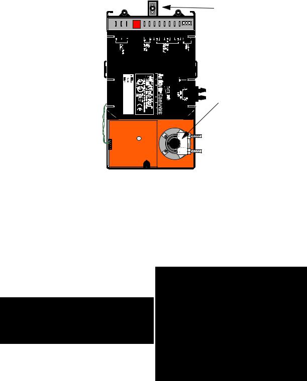
2. Loosen the nuts that attach the mounting U-bolt to the actuator motor.
U-bolt clamp with nuts
Manual override button
3.Manually, position the damper blade at its fully closed position.
4.With the manual override button depressed, rotate the actuator clamp of the TCX 86X
motor counter clockwise to approximately 1/16 - 1/8” between the actuator stop and clamp, depending on seal design. 


TCX 865 Family Installation Guide 3
5.Position the unit at the proper perspective on the VAV box. Carefully insert the shaft of the VAV unit into the opening of the actuator motor through the U-bolt. Make sure the TCX 86X is flush with the VAV housing. Finger tighten the nuts to secure the shaft to the actuator.
6.Insert the supplied self-tapping screw through the grommet and secure the TCX 86X to the housing.
Self-tapping screw secures the unit to the housing
Shaft inserted into the actuator.
7. Tighten the U-Bolt to the shaft using an 8 mm wrench.
Overall Dimensions
The TCX 865 Series are designed to fit over an existing VAV shaft and be mounted to the housing. It is secured via one sheet metal screw. The overall dimensions of the unit are:
4 Andover Controls Corporation
Loading...