


 Loading...
USER MANUAL
Saphyr
Ref. SPX450


 THANK YOU
By following these simple steps you will be able to obtain the most from your powerful Saphyr and its many features.
 1. TRADEMARKS
 2. INTRODUCTION
 3. TERMS AND DEFINITIONS
 4. HARDWARE SPECIFICATIONS
7
7
8
9
4.1 Safety instructions |
9 |
4.1.1English
4.1.2French
4.1.3Italian
4.1.4German
4.1.5Spanish
4.2 Unpacking and inspection |
14 |
4.3 Rack mount information |
14 |
4.4 Cable and adaptor information |
15 |
4.5 Hardware specifications |
15 |
4.5.1Signal descriptions
4.5.2Supported video formats
4.5.3Computer formats
4.5.4Input Computer formats
4.5.5Output Computer formats
4.6 |
Input specifications |
17 |
4.7 |
Output specifications |
19 |
4.7.1Standard output
4.7.2Video output
4.8 Communication specifications |
20 |
4.8.1Serial interface
4.8.2LAN interface
4.9 Environmental specifications |
22 |

4.10 HDCP management |
23 |
4.10.1Input HDCP detection
4.10.2Output HDCP detection
4.10.3Keys’ checking
4.10.4Output management
4.10.5HDCP Classification
4.10.6Status
5. CONNECTING THE SAPHYR |
24 |
|
5.1 |
Description |
24 |
|
5.1.1 Rear panel |
|
|
5.1.2 Front panel |
|
6. CONTROLLING THE SAPHYR |
26 |
|
6.1 |
RCS² requirement |
26 |
6.2 |
Connecting with the RCS² |
26 |
6.3 |
RCS² top menu |
28 |
|
6.3.1 Setup |
|
|
6.3.2 Edit |
|
|
6.3.3 Live |
|
7. OPERATING THE SAPHYR FROM THE RCS² |
29 |
|
7.1 |
Operating mode |
29 |
7.2 Setup |
29 |
|
|
7.2.1 Mode |
|
|
7.2.2 Audio |
|
|
7.2.3 Screens |
|
7.2.4 Preview
7.2.5 Misc
7.2.6 Output management 7.2.7 Input management
7.2.8 Logo/frame management 7.2.9 Video out
7.2.10 Audio management 7.2.11 Service management 7.2.12 Control management
7.3 Edit |
41 |
7.3.1Layer management
7.3.2Layer adjustments
7.3.3Effects
7.3.4Background Frame
7.3.5Preset load and save management
7.4 Live |
47 |

8. OPERATING THROUGH THE FRONT PANEL |
49 |
8.1 Front panel |
49 |
8.1.1Menu navigation
8.1.2Home menu
8.1.3Operating modes
8.1.4Reseting default values
8.1.5Saphyr color codes
8.2 Settings in Mixer mode |
50 |
8.2.1Source Input selection
8.2.2Input selection settings
8.2.3Source Output selection
8.2.4Output selection settings
8.2.5Preview features
8.2.6Preview mode and OSD settings
8.2.7Preview Id
8.2.8How to use the Mosaic Preview feature
8.2.9Working with layers
8.2.10Working with layers functions
8.2.11Opening transitions and closing live layers
8.2.12Layer adjustment menu
8.2.13Layers with transitions & borders
8.2.14Capturing frames
8.2.15Working with frames
8.2.16Opening transitions & closing still layers (logos or frames)
8.2.17Frame input setup menu
8.2.18Frames as layer
8.2.19Layer transitions & effects
8.2.20Capturing logos
8.2.21Capturing an animated logo
8.2.22Logos input setup menu
8.2.23Working with logos
8.2.24Logos as layer
8.2.25Creating presets
8.2.26Working with presets
8.2.27Working with audio
8.2.28Special features
8.3 Settings in native Matrix mode |
65 |
8.3.1Source Input selection
8.3.2Input selection settings
8.3.3Working with layers
8.3.4Source Output selection
8.3.5Output selection settings
8.3.6Working with native Matrix mode
8.3.7Working with Cut, Fade or Transitions
8.3.8Working with presets in Matrix mode
8.3.9Working with Mirror modes

8.3.10 Working with frames/logos |
|
8.4 Menu tree |
70 |
9. MAINTENANCE AND SUPPORT |
97 |
|
9.1 Dashboard (RCS²) |
97 |
|
10. APPLICATIONS NOTE AND TIPS |
98 |
|
10.1 HDCP |
98 |
|
11. WARRANTY |
99 |
|
11.1 |
Warranty conditions |
99 |
11.2 |
Repair and return instructions |
99 |
11.3 |
Return conditions |
99 |
12. CONTACT INFORMATION |
100 |
|
13. APPENDICES |
101 |
|
13.1 |
Crestron 2&3 series Midra™ Driver |
101 |
13.2 |
AMX NetLinx® Integrated Controllers Midra™ Driver |
101 |
6

1. Trademarks
 1. TRADEMARKS
ThetermsHDMI,HDMIHigh-DefinitionMultimediaInterfaceandtheHDMIlogoaretrademarksorregistered trademarks of HDMI Licensing LLC in the United States and other countries.
 2. INTRODUCTION
Thank you for choosing the Analog Way Saphyr. Before you start setting up your Saphyr for the first time, please read through all of the documentation to become familiar with its powerful features. The Saphyr can be used in several configurations, which results in a versatile video production tool for live event staging and fixed installation applications.
7

3. Terms and definitions
 3. TERMS AND DEFINITIONS
BACKGROUND: a “Background” is a source, typically originating from a computer. Saphyr enables you to work with still (frame) background — visually in back of all other sources.
LAYER: a“layer”isanimagedisplayelement(suchasaPIPwindow,Key,logoorBackground)thathasavisual priority — either in front (or in back) of another layer. 1 frame non-resizable, up to 4 live layers resizable and 2 logos available on the Saphyr.
PIP: a “PIP” (Picture In Picture) is a picture, typically of reduced size, which is positioned over another background image or other PIPs. PIPs can be repositioned, reduced, enlarged and displayed with borders. PIPscanoverlap,dependingontheirvisualpriority.Saphyr offersvariousslides,wipes,andfadesfordynamic PIPentrancesand exits. A“flying” PIPisalso possible using vertical,horizontal,ordiagonal movement.APIP is considered as a layer.
FRAME: a “frame” is a full screen image which is selected from one of the still frames you can capture. A frame can be captured in flash memory from any video or computer source plugged into the machine.
LOGO: a“logo”isapartofascreenimagethatcanbecapturedinflashmemoryfromanyvideoorcomputer source, by keying or image cut-out. A logo can be positioned anywhere on the screen.
KEYING: “Key” is an electronic process whereby a video image is electronically superimposed over another sourceorbackground,bydynamicallyremovingaportionofthefirstimage.Forexample,removingallcontent ofacertaincolor(suchasgreenorblue)iscalledaChromaKey,andremovingcontentbasedonitsbrightness or luminance levels is called a (Luma Key). Keys are typically used for titles, logos and special effects. Saphyr allows you to key a live source (such as a camera shot with green or blue background, or a title with a black background) over any other source or sources.
SEAMLESS: Cleantransitionwithnoglitchorlossofsyncwhileswitchingbetweentwosources.Forexample, fading through black to another source is a seamless transition.
TRUE SEAMLESS: Clean seamless transitions with no glitch or freeze between two sources. For example, crossfading from source to source is a true seamless transition.
RCS²: Remote Control Software used to control, set up, and operate the device.
QUICK FRAME: The “Quick Frame” feature allows the instant display of a stored frame above all layers.
8

4.1.1 English
 4. HARDWARE SPECIFICATIONS
4.1 Safety instructions
4.1.1 English
All of the safety and operating instructions should be read before the product is operated and should be maintained for further reference. Please follow all of the warnings on this product and its operating instructions.
•WARNING: To prevent the risk of electric shock and fire, do not expose this device to rain, humidity or intenseheatsources(suchasheatersanddirectsunlight).Slotsandopeningsinthedeviceareprovidedfor ventilationandtoavoidoverheating.Makesurethedeviceisneverplacednearatextilesurfacethatcould block the openings. Also keep away from excessive dust, vibrations and shocks.
•POWER: Only use the power supply indicated on the device of the power source. Devices equipped with a grounding plug should only be used with a grounding type outlet. In no way should this grounding be modified, avoided or suppressed. Connection of equipment to main supply must be after branch circuit breaker of the building installation.
•POWER CORD: The device is equipped with a detachable power cord, to remove mains disconnect it at appliance coupler. A rear switch is also available, turn OFF to switch off the device.
Caution: The power cord constitutes the only mean to completely disconnect the equipment from the main
power.
Apply the following guidelines:
-The equipment connected to the network must have a release system easily accessible and located outside the unit.
-Unplug the power cord; do not pull on the power cord but always on the plug itself.
-The outlet should always be near the device and easily accessible.
-Power supply cords should be routed so that they are not likely to be walked on or pinched by items placed upon or against them.
Ifthepowersupplycordisdamaged,unplugthedevice.Usingthedevicewithadamagedpowersupplycord may expose your device to electric shocks or other hazards. Verify the condition of the power supply cords once in a while. Contact your dealer or service center for replacement if damaged.
•CONNECTIONS: All inputs and outputs (except for the power input) are Safety Extra Low Voltage (SELV) circuits as defined in UL/IEC 60950-1.
•SERVICING: Do not attempt to service this product yourself by opening or removing covers and screws since it may expose your device to electric shocks or other hazards. Refer all problems to qualified service personnel. You may lose warranty when you open the unit.
•OPENINGS: Never push objects of any kind into this product through the openings. If liquids have been spilled or objects have fallen into the device, unplug it immediately and have it checked by a qualified technician.
9

4.1.2French
4.1.2French
Afin de mieux comprendre le fonctionnement de cet appareil nous vous conseillons de bien lire toutes les consignes de sécurité et de fonctionnement avant utilisation. Conservez les instructions de sécurité et de fonctionnement afin de pouvoir les consulter ultérieurement. Respectez toutes les consignes marquées dans la documentation, sur le produit et sur ce document.
•ATTENTION : Afin de prévenir tout risque de choc électrique et d’incendie, ne pas exposer cet appareil à la pluie, à l’humidité ou à des sources de chaleur intense.
•INSTALLATION : Veillez à assurer une circulation d’air suffisante pour éviter toute surchauffe à l’intérieur de l’appareil.Neplacezpasl’appareilsurouàproximitéd’unesurfacetextilesusceptibled’obstruerlesorificesde ventilation.N’installezpasl’appareilàproximitédesourcesdechaleurcommeunradiateurouunepoched’air chaud, ni dans un endroit exposé au rayonnement solaire direct, à des poussières excessives, à des vibrations ou à des chocs mécaniques. Ceci pourrait provoquer un mauvais fonctionnement et un accident.
•ALIMENTATION : Ne faire fonctionner l’appareil qu’avec la source d’alimentation indiquée sur l’appareil. Lesappareilsdoiventêtreobligatoirementconnectéssurunesourceéquipéed’unemiseàlaterreefficace. En aucun cas cette liaison de terre ne devra être modifiée, contournée ou supprimée. Raccordement des équipementsàl’alimentationprincipaledoitêtrepostérieuraudisjoncteurdebranchementdel’installation électrique du bâtiment.
•CORDON D’ALIMENTATION : Les appareils sont équipés d’un cordon d’alimentation détachable, la mise hors tension se fait en débranchant ce cordon de l’appareil. L’appareil possède un interrupteur en face arrière, appuyez dessus pour éteindre l’appareil.
Attention : le cordon d’alimentation constitue le seul moyen de débrancher l’appareil totalement de l’alimentation secteur. Pour être certain que l’appareil n’est plus alimenté, ce cordon doit être débranché de la prise murale.
Appliquer les consignes suivantes :
-Lematérielreliéàdemeureauréseau,doitavoirundispositifdesectionnementfacilementaccessible qui doit être incorporé à l’extérieur de l’appareil.
-Débrancher le cordon d’alimentation de la prise murale si vous prévoyez de ne pas utiliser l’appareil pendant quelques jours ou plus.
-Pour débrancher le cordon, tirez-le par la fiche. Ne tirez jamais sur le cordon proprement dit.
-La prise d’alimentation doit se trouver à proximité de l’appareil et être aisément accessible.
-Ne laissez pas tomber le cordon d’alimentation et ne posez pas d’objets lourds dessus.
Si le cordon d’alimentation est endommagé, débranchez-le immédiatement de la prise murale. Il est dangereuxdefairefonctionnerunappareilavecuncordonendommagé;uncâbleabîmépeutprovoquerun risque d’incendie ou un choc électrique. Vérifiez le câble d’alimentation de temps en temps. Contactez votre revendeur ou le service après-vente pour un remplacement.
•CONNEXIONS : Toutes les entrées et sorties (exceptée l’entrée d’alimentation) sont des circuits de très basse tension de sécurité (TBTS) tels que définis dans UL / IEC 60950-1.
•RÉPARATION ET MAINTENANCE : L’utilisateur ne doit en aucun cas essayer de procéder aux opérations de dépannage, car l’ouverture des appareils par retrait des capots ou de toutes autres pièces constituant les boîtiers ainsi que le dévissage des vis apparentes à l’extérieur, risquent d’exposer l’utilisateur à des chocs électriques ou autres dangers. Contactez le service après-vente, votre revendeur ou adressez-vous à un personnel qualifié uniquement. L’ouverture de l’appareil provoque la perte de la garantie.
•OUVERTURES ET ORIFICES : Les appareils peuvent comporter des ouvertures (aération, fentes, etc...), veuillez ne jamais y introduire d’objets et ne jamais obstruer ses ouvertures. Si un liquide ou un objet pénètre à l’intérieur de l’appareil, débranchez immédiatement l’appareil et faites-le contrôler par un personnel qualifié avant de le remettre en service.
10
4.1.3 Italian
4.1.3 Italian
Allo scopo di capire meglio il funzionamento di questa apparecchiatura vi consigliamo di leggere bene tutti i consigli di sicurezza e di funzionamento prima dell’utilizzo. Conservare le istruzioni di sicurezza e di funzionamento al fine di poterle consultare ulteriormente. Seguire tutti i consigli indicati su questo manuale e sull’apparecchiatura.
•ATTENZIONE:Alfinediprevenirequalsiasirischiodishockelettricoed’incendio,nonesporrel’apparecchiatura a pioggia, umidità e a sorgenti di eccessivo calore.
•INSTALLAZIONE: Assicuratevi che vi sia una sufficiente circolazione d’aria per evitare qualsiasi surriscaldamento all’interno dell’apparecchiatura. Non collocare l’apparecchiatura in prossimità o su superfici tessili suscettibili di ostruire il funzionamento della ventilazione. Non installate l’apparecchiatura in prossimità di sorgenti di calore come un radiatore o una fuoruscita d’aria calda, né in un posto esposto direttamenteairaggidelsole,apolvereeccessiva,avibrazionioashockmeccanici.Ciópotrebbeprovocare un erroneo funzionamento e un incidente.
•ALIMENTAZIONE: Far funzionare l’apparecchiatura solo con la sorgente d’alimentazione indicata sull’apparecchiatura.Leapparecchiaturequestedevonoessereobbligatoriamentecollegatesuunasorgente fornitadiunaefficientemessaaterra.Innessuncasoquestocollegamentopotràesseremodificato,sostituito o eliminato. Connessione delle apparecchiature alla rete elettrica deve essere successiva interruttore di circuito dell’impianto dell’edificio
•CAVO DI ALIMENTAZIONE: Il dispositivo è dotato di un cavo di alimentazione removibile, per rimuovere alimentazione scollegarlo dalla Presa. L’interruttore di accensione e’ disponibile sul pannello posteriore, posizionarlo su OFF per spegnere il dispositivo.
Attenzione: il cavo di alimentazione è il solo modo di disconnettere l’apparecchio dell’alimentazione. Per assicurarsi che totalemente l’apparecchio non è più collegato, il cavo deve essere disconesso della presa murale.
Seguire le instruzioni seguenti:
-Il materiale collegato a residenza alla rete, deve avere un dispositivo di sezionamento facile da raggiongere eche deve essere inserito all’esterno del apparecchio.
-Disconnetterel’apparecchiaturadallapresamuralesesiprevededinonutilizzarlaperqualchegiorno.
-Per disconnettere il cavo tirare facendo forza sul connettore.
-La presa d’alimentazione deve trovarsi in prossimità dell’apparecchiatura ed essere facilmente accessibile.
-Non far cadere il cavo di alimentazione né appoggiarci sopra degli oggetti pesanti. Se il cavo di alimentazione é danneggiato, spegnere immediatamente l’apparecchiatura.
E’ pericoloso far funzionare questa apparecchiatura con un cavo di alimentazione danneggiato, un cavo graffiatopuóprovocareunrischiodiincendioounoshockelettrico.Verificareilcavodialimentazionespesso. Contattare il vostro rivenditore o il servizio assistenza per una sostituzione.
•CONNESSIONE: Tuttigliingressieleuscite(trannecheperlapotenzainingresso)sonobassissimatensione di sicurezza (SELV) circuiti definiti UL / IEC 60950-1.
•RIPARAZIONI E ASSISTENZA: L’utilizzatore non deve in nessun caso cercare di riparare l’apparecchiatura, poiché con l’apertura del coperchio metallico o di qualsiasi altro pezzo costituente la scatola metallica, nonché svitare le viti che appaiono esteriormente, poiché ció puó provocare all’utilizzatore un rischio di shock elettrico o altri rischi. Qualora si apra l’unita’, la garanzia non sara’ più’ valida.
•APERTURE DI VENTILAZIONE: Le apparecchiature possono comportare delle aperture di ventilazione, si prega di non introdurre mai oggetti o ostruire le sue fessure. Se un liquido o un oggetto penetra all’interno dell’apparecchiatura, disconnetterla e farla controllare da personale qualificato prima di rimetterla in servizio.
11

4.1.4German
4.1.4German
Um den Betrieb dieses Geräts zu verstehen, raten wir Ihnen vor der Inbetriebnahme alle Sicherheits und Betriebsanweisungengenauzulesen.DieseSicherheits-undBetriebsanweisungenfüreinenspäterenGebrauch sicher aufbewahren. Alle in den Unterlagen, an dem Gerät und hier angegebenen Sicherheitsanweisungen einhalten.
•ACHTUNG: um jegliches Risiko eines Stromschlags oder Feuers zu vermeiden, das Gerät nicht Regen, Feuchtigkeit oder intensiven Wärmequellen aussetzen.
•EINBAU: Eine ausreichende Luftzufuhr sicherstellen, um jegliche Überhitzung im Gerät zu vermeiden. Das GerätnichtaufundinNähevonTextiloberflächen,dieBelüftungsöffnungenverschließenkönnen,aufstellen. Das Gerät nicht in Nähe von Wärmequellen, wie z.B. Heizkörper oder Warmluftkappe, aufstellen und es nicht dem direkten Sonnenlicht, übermäßigem Staub, Vibrationen oder mechanischen Stößen aussetzen. Dies kann zu Betriebsstörungen und Unfällen führen.
•STROMVERSORGUNG: DasGerätnurmitderaufdemGerätbezeichneteStromquellebetreiben.Gerätmit geerdeter Hauptstromversorgung muss an eine Stromquelle mit effizienter Erdung angeschlossen werden. Diese Erdung darf auf keinen Fall geändert, umgangen oder entfernt werden. Anschluss von Geräten ans Stromnetz muss nach Abzweigschalter des Gebäudes Installation
•NETZKABEL: Das Gerät ist mit einem lösbaren Netzkabel ausgestattet ; um es völlig vom Netz zu trennen, ziehen Sie bitte das Netzkabel aus der Kaltgerätebuchse. Des Weiteren befindet sich auf der Rückseite ein Schalter, mit dem das Gerät ausgeschaltet werden kann.
Achtung: DasNetzkabelstelltdieeinzigeMöglichkeitdar,dasGerätvollständigvomNetzanschlusszutrennen. Um sicherzustellen, dass das Gerät nicht mehr versorgt wird, muss dieses Kabel aus der Netzsteckdose ausgesteckt werden.
Bitte beachten Sie die folgenden Hinweise:
-Wenn Geräte dauerhaft am Netz bleiben, müssen sie über eine leicht zugängliche Trennvorrichtung verfügen, die außen am Gerät angebracht sein muss.
-Das Kabel mittels dem Stecker herausziehen. Niemals am Stromkabel selbst ziehen.
-Die Steckdose muß sich in der Nähe des Geräts befinden und leicht zugänglich sein.
-Das Stromkabel nicht fallen lassen und keine schweren Gegenstände auf es stellen.
Wenn das Stromkabel beschädigt ist, das Gerät sofort abschalten. Es ist gefährlich das Gerät mit einem beschädigten Stromkabel zu betreiben; ein abgenutztes Kabel kann zu einem Feuer oder Stromschlag führen. Das Stromkabel regelmäßig untersuchen. Für den Ersatz, wenden Sie sich an Ihren Verkäufer oder
Kundendienststelle.
•ANSCHLÜSSE: Alle Eingänge und Ausgänge (mit Ausnahme der Stromversorgung) sind Safety Extra Low Voltage (SELV) Schaltungen wie in UL / IEC 60950-1 definiert.
•REPARATUR UND WARTUNG: Der Benutzer darf keinesfalls versuchen das Gerät selbst zu reparieren, die ÖffnungdesGerätsdurchAbnahmederAbdeckhaubeoderjeglichenanderenTeilsdesGehäusessowiedie Entfernung von außen sichtbaren Schrauben zu Stromschlägen oder anderen Gefahren für den Benutzer führen kann. Wenden Sie sich an Ihren Verkäufer, Ihre Kundendienststelle oder an qualifizierte Fachkräfte. Das Öffnen des Gehäuses führt zum Verlust der Garantie.
•ÖFFNUNGEN UND MUNDUNGEN: DieGerätekönnenüberÖffnungenverfügen(Belüftung,Schlitze,usw.). Niemals Gegenstände in die Öffnungen einführen oder die Öffnungen verschließen. Wenn eine Flüssigkeit odereinGegenstandindasGerätgelangt,denSteckerherausziehenundesvoreinerneuenInbetriebnahme von qualifiziertem Fachpersonal überprüfen lassen.
12

4.1.5 Spanish
4.1.5 Spanish
Paracomprendermejorelfuncionamientodeesteaparato,lerecomendamosqueleacuidadosamentetodas las consignas de seguridad y de funcionamiento del aparato antes de usarlo. Conserve las instrucciones de seguridad y de funcionamiento para que pueda consultarlas posteriormente. Respete todas las consignas indicadas en la documentación, relacionadas con el producto y este documento.
•CUIDADO: Para prevenir cualquier riesgo de choque eléctrico y de incendio, no exponga este aparato a la lluvia, a la humedad ni a fuentes de calorintensas.
•INSTALACIÓN: Cerciórese de que haya una circulación de aire suficiente para evitar cualquier sobrecalentamiento al interior del aparato. No coloque el aparato cerca ni sobre una superficie textil que pudieraobstruirlosorificiosdeventilación.Noinstaleelaparatocercadefuentesdecalorcomoradiadoro bocadeairecaliente,nienunlugarexpuestoalosrayossolaresdirectosoalpolvoexcesivo,alasvibraciones o a los choques mecánicos. Esto podría provocar su mal funcionamiento o un accidente.
•ALIMENTACIÓN: Ponga a funcionar el aparato únicamente con la fuente de alimentación que se indica en el aparato. Los aparatos deben estar conectados obligatoriamente a una fuente equipada con una puesta a tierra eficaz. Por ningún motivo este enlace de tierra deberá ser modificado, cambiado o suprimido. Conexión del equipo a la red eléctrica debe ser posterior del interruptor de circuitos derivados de la instalación del edificio
•CABLE DE CORRIENTE: Elequiposesuministraconuncabledecorriente sidesconectamoselcabledejamos al equipo sin alimentación. Un interruptor situado en la trasera de la unidad, permite apagar el equipo.
Atención: El cable de alimentación constituye el único medio de desconectar el aparato totalmente de la red eléctrica. Para estar seguro de que el aparato no está más alimentado, este cable debe de ser desconectado de la toma de corriente.
Aplicar las siguientes consignas:
-Elmaterialconectadoaresidenciaalaredinformática,debedetenerundispositivodeseccionamiento fácilmente accesible que debe de ser incorporado al exterior del aparato.
-Desconectar el aparato del enchufe mural si no piensa utilizarlo durante varios días.
-Para desconectar el cable, tire de la clavija. No tire nunca del cable propiamente dicho.
-El enchufe de alimentación debe estar cerca del aparato y ser de fácil acceso.
-No deje caer el cable de alimentación ni coloque objetos pesados encima de él.
Si el cable de alimentación sufriera algún daño, ponga el aparato inmediatamente fuera de tensión. Es peligroso hacer funcionar este aparato con un cable averiado, ya que un cable dañado puede provocar un incendio o un choque eléctrico. Verifique el estado del cable de alimentación de vez en cuando. Póngase en contacto con su distribuidor o con el servicio de posventa si necesita cambiarlo.
•CONEXIONES: Todaslasentradasysalidas(aexcepcióndelaentradadealimentación)sondetensiónextra baja de seguridad (SELV) circuitos definidos en UL / IEC 60950-1.
•REPARACIÓN Y MANTENIMIENTO: Por ningún motivo, el usuario deberá tratar de efectuar operaciones de reparación, ya que si abre los aparatos retirando el capó o cualquier otra pieza que forma parte de las cajasosidestornillalostornillosaparentesexteriores,existeelriesgodeproducirseunaexplosión,choques eléctricos o cualquier otro incidente. Contacte el servicio de posventa, a su distribuidor o dirigirse con personal cualificado únicamente. La unidad pierde la garantía si esta ha sido abierta.
•ABERTURAS Y ORIFICIOS: Los aparatos pueden contener aberturas (aireación, ranuras, etc.). Nointroduzca allíningúnobjetoniobstruyanuncaestasaberturas.Siunlíquidoounobjetopenetraalinteriordelaparato, desconéctelo y hágalo revisar por personal cualificado antes de ponerlo nuevamente en servicio.
13

4.2Unpacking and inspection
4.2Unpacking and inspection
•1 x Saphyr (SPX450)
•1 x Power supply cord
•1 x Ethernet cross cable (for device update)
•1 x Remote Control Software (RCS²)*
•1 x Set of 6 audio 5-pin screw terminals
•1 x Front rack ears (the parts are stowed in the packaging foam)
•1 x User manual (PDF)*
•1 x Quick start guide*
* User manual, quick start guide and the RCS² are available on www.analogway.com
Beforerackingandplugginganyinputsandoutputs,itisadvisedtopowerontheunit.Shouldyouencounter any issue, you must contact immediately your local distributor or dealer, or closest Analog Way technical support offices (see chapter: 12. Contact information).
4.3 Rack mount information
Tabletop mounting: The Saphyr can be used directly on a table; the unit is equipped with 4 handy anti-slip rubber feet.
Rack mounting: TheSaphyr iscompatiblewitha19”enclosure.Pleasefollowtheinstructionsbelowtoinstall
the device in a 19” rack.
Placethedeviceinyourrack.Attachthedevicetotherackbyscrewing2frontearsonit(screwsnotincluded).
Rear fixing is also recommended, in particular for permanent installations.
Connect all of the cables of the device and attach them to the rack with the help of tie wraps.
IMPORTANT:
-The openings in the side of the device are for cooling. Do not cover these openings to avoid blocking air circulation.
-Be sure that no weight in excess of 2 kg (4.4 Lbs.) is added onto the Saphyr.
-The maximum ambient operating temperature should not exceed 40°C (104°F).
-The rack and all mounted equipment in it must be reliably grounded according to national and/or local electrical standards.
Dismantlingfronthandlesofthedevicecouldinvalidatewarrantyonafter-salesservicesofyour Saphyr. It is strongly advised to avoid using front handles as rests for your Saphyr, they are  designed for manipulation purposes only.
If required,front handles of the devicecan be dismantled, but with caution. The original screws removed must not be reintroduced to their location without handles in place. Substantial damages can occur, including risk of electric shock from the main voltage. Only M4x12mm screws can be used. They are supplied with the unit.
14

4.4 Cable and adaptator information
4.4 Cable and adaptor information
A large choice of cables and adaptors are compatible with the Saphyr. Please refer to the hardware specifications chapter to find the most suitable cables for your operations.
4.5 Hardware specifications
4.5.1 Signal descriptions
For each type of signal, here are the levels and the impedance accepted by the Saphyr.
Analog SDTV
Type |
Levels |
|
Impedance |
Composite |
0,7 Vpp + 0,3 Vpp |
|
75 Ω |
|
|
|
|
S. Video |
Y = 0,7 Vpp + 0,3 Vpp |
|
75 Ω |
|
C = 0,7 Vpp |
|
|
|
|
|
|
YUV |
Y = 0,7 Vpp + 0,3 Vpp |
|
|
|
U = 0,7 Vpp |
|
75 Ω |
|
V = 0,7 Vpp |
|
|
RGsB |
R = 0,7 Vpp |
|
|
|
G = 0,7 Vpp + 0,3 Vpp |
|
75 Ω |
|
B = 0,7 Vpp |
|
|
|
R, G, B = 0,7 Vpp |
|
R, G, B = 75 Ω |
|
|
|
|
RGBS |
S = 0,3 Vpp 75 Ω |
||
or |
|
||
|
|
||
|
S = TTL |
|
|
Digital SDTV
Type |
Characteristics |
SD-SDI |
YUV - 10 bits – 4.2.2 - 270 Mb/s |
|
No payload ID management |
|
Only A-level type |
DVI |
RGB ou YUV – 8 bits – 4.4.4 – 16/235 - TMDS |
HDMI |
RGB or YUV – 8 bits – 4.4.4 or 4.2.2 |
|
– 16/235 – TMDS |
Analog EDTV
Type |
Levels |
|
Impedance |
YUV |
Y = 0,7 Vpp + 0,3 Vpp |
|
|
|
U = 0,7 Vpp |
|
75 Ω |
|
V = 0,7 Vpp |
|
|
RGsB |
R = 0,7 Vpp |
|
|
|
G = 0,7 Vpp + 0,3 Vpp |
|
75 Ω |
|
B = 0,7 Vpp |
|
|
|
R, G, B = 0,7 Vpp |
|
R, G, B = 75 Ω |
RGBS |
S = 0,3 Vpp 75 Ω |
||
or |
|
||
|
|
||
|
S = TTL |
|
|
|
|
|
|
Analog HDTV
These formats are compatible with bi-level and trilevel sync on 1 or 3 wires.
Type |
Levels |
Impedance |
YUV |
Y = 0,7 Vpp ±0,3 Vpp |
|
|
U = 0,7 Vpp ±0,3 Vpp |
75 Ω |
|
V = 0,7 Vpp ±0,3 Vpp |
|
RGsB |
R = 0,7 Vpp ±0,3 Vpp |
|
|
G = 0,7 Vpp ±0,3 Vpp |
75 Ω |
|
B = 0,7 Vpp ±0,3 Vpp |
|
Digital EDTV
Type |
Characteristics |
DVI |
RGB or YUV – 8 bits – 4.4.4 – 16/235 - TMDS |
HDMI |
RGB or YUV – 8 bits – 4.4.4 or 4.2.2 |
|
– 16/235 – TMDS |
Digital HDTV
Type |
Characteristics |
HD-SDI |
YUV - 10 bits – 4.2.2 – 1,485Gb/s and |
|
1,485/1.001Gb/s |
|
Only A-level type |
|
Input and output payload ID management |
|
for HDTV format only |
|
|
3G-SDI |
YUV - 10 bits – 4.2.2 – 2,97Gb/s and |
|
2,97/1.001Gb/s |
|
Only A-level type |
|
Input and output payload ID management |
|
for HDTV format only |
DVI |
RGB or YUV – 8 bits – 4.4.4 – 16/235 - TMDS |
|
|
HDMI |
RGB or YUV – 8 bits – 4.4.4 or 4.2.2 |
|
– 16/235 – TMDS |
15

4.5.2 Supported video formats
Analog computer
Type |
Levels |
Impedance |
|
RGsB |
R = 0,7 Vpp |
|
|
|
G = 0,7 Vpp + 0,3 Vpp |
75 Ω |
|
|
B = 0,7 Vpp |
|
|
RGBS |
R, G, B = 0,7 Vpp |
R, G, B = 75 Ω |
|
S = 0,3 Vpp 75Ω or S = TTL |
|||
|
|||
|
|
|
|
RGBHV |
R, G, B = 0,7 Vpp |
R, G, B = 75 Ω |
|
H = TTL and V = TTL |
|||
|
|||
Digital computer
Type |
Characteristics |
DVI |
RGB – 8 bits – 4.4.4 – 0/255 - TMDS |
|
|
HDMI® |
RGB or YUV – 8 bits – 4.4.4 or 4.2.2 |
|
– 0/255 – TMDS |
4.5.2 Supported video formats
The Saphyr can support all the following video formats:
SDTV formats
Standard |
Size |
Vertical frequency |
Horizontal frequency |
NTSC |
525/480i |
59.94Hz/60Hz |
15,735 KHz |
|
|
|
|
PAL |
625/576i |
50Hz |
15.625 KHz |
SECAM |
625/576i |
50Hz |
15.625 KHz |
EDTV formats
Standard |
Size |
Vertical frequency |
Horizontal frequency |
480p |
525/480p |
59.94Hz/60Hz |
31.47 KHz |
|
|
|
|
576p |
625/576p |
50Hz |
31.25 KHz |
HDTV formats
Standard |
Size |
Vertical frequency |
720p |
1280 x 720 |
23.97Hz/24Hz/25Hz/29,97Hz/30Hz/50Hz/59.94Hz/60Hz |
|
|
|
1035i |
1920 x 1035 |
59.94Hz/60Hz |
|
|
|
1080i |
1920 x 1080 |
50Hz/59.94Hz/60Hz |
1080sF |
1920 x 1080 |
50Hz/59.94Hz/60Hz |
|
|
|
1080p |
1920 x 1080 |
23.97Hz/24Hz/25Hz/29,97Hz/30Hz/50Hz/59.94Hz/60Hz |
|
|
|
Cinema formats
Format |
Size |
Vertical frequency |
DCDM |
2048 x 1080 |
24Hz |
|
|
|
4.5.3 Computer formats
Important: The maximum pixel clock frequency is 165 MHz. Supported formats include 1920x1200 @ 60hz RB, 1600x1200 @60hz RB, 2048x1152 @60hz RB.
4.5.4 Input Computer formats
The Saphyr inputs support GTF (version 1.1), CVT (version 1.1) and DMT (version 1.0 rev 12) standards. All others non-standard formats are supported via the custom format capability of the framework.
16

4.5.5 Output computer formats
4.5.5 Output Computer formats
The Saphyr outputs support GTF (version 1.1), CVT (version 1.1) and DMT (version 1.0 rev 12) standards. Other non-standard formats are supported via the custom format capability of the framework.
The Saphyr offers a list of pre-defined output formats. The list of output formats is always displayed from increasing number of pixels per line and then number of lines.
Format |
Size |
Aspect ratio |
Frequency |
|
50 Hz |
60 Hz |
|||
VGA |
640x480 |
4/3 |
Yes |
Yes |
WVGA |
848x480 |
16/9 |
Yes |
Yes |
SVGA |
800x600 |
4/3 |
Yes |
Yes |
720p |
1280x720 |
16/9 |
Yes |
Yes |
XGA |
1024x768 |
4/3 |
Yes |
Yes |
WXGA |
1280x768 |
5/3 |
Yes |
Yes |
SWXGA |
1360x768 |
16/9 |
Yes |
Yes |
1366x768 |
1366x768 |
16/9 |
Yes |
Yes |
WXGA2 |
1280x800 |
16/9 |
Yes |
Yes |
SWXGAP |
1366x800 |
5/3 |
Yes |
Yes |
|
1152x864 |
4/3 |
Yes |
Yes |
900p |
1440x900 |
16/10 |
Yes |
Yes |
|
1440x900 |
3/2 |
Yes |
Yes |
|
1600x900 |
16/9 |
Yes |
Yes |
|
1280x960 |
4/3 |
Yes |
Yes |
SXGA |
1280x1024 |
5/4 |
Yes |
Yes |
|
1360x1024 |
4/3 |
Yes |
Yes |
SXGAP |
1400x1050 |
5/3 |
Yes |
Yes |
Format |
Size |
Aspect ratio |
Frequency |
|
50 Hz |
60 Hz |
|||
WSXGAP |
1680x1050 |
16/9 |
Yes |
Yes |
1080p |
1920x1080 |
16/9 |
Yes |
Yes |
2K |
2048x1080 |
17/9 |
Yes |
Yes |
UXGA |
1600x1200 |
4/3 |
Yes |
Yes |
WUXGA |
1920x1200 |
16/9 |
Yes |
Yes |
|
2048x1152 |
16/9 |
Yes |
Yes |
4.6 Input specifications
The Saphyr offers 10 seamless inputs. Some inputs contain several plugs.
A plug corresponds to a socket or connector on the rear panel.
The following types of plugs are available on the rear panel:
-HDMI
-Single DVI-D (HDMI compatible),
-3G/HD/SD-SDI (BNC),
-Universal Analog (HD-15)
17

4.6 Input specifications
The Saphyr uses an HDMI plug with a standard mounting screwabovetheconnector. Pleaseseethediagrambelow. This hole is occupied by a Torx10 screw when you receive the unit. If desired, this screw can be removed and replaced by a compatible aftermarket HDMI plug locking mechanism to ensure a secure HDMI connection. This threaded hole should not be left empty.
M3x0,5 mm
27 mm
ThisholeisusedbyaTX10screwwhenyoureceivetheunit,ifyouwishtouseanHDMIcablewithasecurity fixing screw you can take this screw off and use your own in order to insure good fixing of your HDMI plug.
Please take a look at the accepted formats regarding the input plug type:
Plug Type |
Formats |
Signals |
Universal Analog Input |
SDTV - EDTV - HDTV - Computer |
Analog SDTV - Analog EDTV - Analog HDTV - Analog Computer |
|
|
|
DVI-D Input |
SDTV - EDTV - HDTV - Computer |
Digital SDTV - Digital EDTV - Digital HDTV - Digital Computer |
|
|
|
HDMI Input |
SDTV - EDTV - HDTV - Computer |
Digital SDTV - Digital EDTV - Digital HDTV - Digital Computer |
3G/HD/SD-SDI Input |
SDTV - HDTV |
Digital SDTV - Digital HDTV |
|
|
|
WARNING: OnlythevideoandaudiosignalisprocessedfortheHDMI®,and3G/HD/SD-SDIinputs;otherem- bedded auxiliary features are not supported or passed through. The embedded audio is processed. All other HDMI® features such as: HDMI Ethernet Channel, Audio Return Channel, 3D, 4K, Content Type, Deep Color and x.v.Color are NOT supported.
Each input can display only one active plug at a time. It is instantly available on the device and can be displayed simultaneously on many layers or outputs, with different sizes and positions.
Standard |
Size |
HD-15 |
3G-SDI |
HDMI |
Single-Link |
|
DVI-D |
||||||
|
|
|
|
|
||
NTSC |
525/480i |
Yes |
Yes |
Yes |
No |
|
PAL |
625/576i |
Yes |
Yes |
Yes |
No |
|
SECAM |
625/576i |
Yes |
Yes |
Yes |
No |
|
EDTV 480p |
525/480p |
Yes |
No |
Yes |
Yes |
|
EDTV 576p |
625/576p |
Yes |
No |
Yes |
Yes |
|
HDTV 720p |
1280x720 |
Yes |
Yes |
Yes |
Yes |
|
HDTV 1035i |
1920x1035 |
Yes |
Yes |
Yes |
Yes |
|
HDTV 1080i |
1920x1080 |
Yes |
Yes |
Yes |
Yes |
|
HDTV 1080p |
1920x1080 |
Yes |
Yes |
Yes |
Yes |
|
HDTV 1080sF |
1920x1080 |
Yes |
Yes |
Yes |
Yes |
|
HDTV 1080p |
1920x1080 |
Yes |
Yes |
Yes |
Yes |
|
HDTV DCDM |
2048x1080 |
No |
Yes |
No |
No |
|
VGA |
640x480 |
Yes |
No |
Yes |
Yes |
|
800x480 |
800x480 |
Yes |
No |
Yes |
Yes |
|
WVGA |
848x480 |
Yes |
No |
Yes |
Yes |
|
SVGA |
800x600 |
Yes |
No |
Yes |
Yes |
|
1280x600 |
1280x600 |
Yes |
No |
Yes |
Yes |
|
720p RGB |
1280x720 |
Yes |
No |
Yes |
Yes |
|
XGA |
1024x768 |
Yes |
No |
Yes |
Yes |
|
WXGA |
1280x768 |
Yes |
No |
Yes |
Yes |
|
SWXGA |
1360x768 |
Yes |
No |
Yes |
Yes |
18

4.7 Output specifications
Standard |
Size |
HD-15 |
3G-SDI |
HDMI |
Single-Link |
|
DVI-D |
||||||
|
|
|
|
|
||
1366x768 |
1366x768 |
Yes |
No |
Yes |
Yes |
|
800p RGB |
1280x800 |
Yes |
No |
Yes |
Yes |
|
SWXGA+ |
1366x800 |
Yes |
No |
Yes |
Yes |
|
1152x864 |
1152x864 |
Yes |
No |
Yes |
Yes |
|
900p RGB |
1440x900 |
Yes |
No |
Yes |
Yes |
|
1600x900 |
1600x900 |
Yes |
No |
Yes |
Yes |
|
960p RGB |
1280x960 |
Yes |
No |
Yes |
Yes |
|
SXGA |
1280x1024 |
Yes |
No |
Yes |
Yes |
|
1360x1024 |
1360x1024 |
Yes |
No |
Yes |
Yes |
|
DILA4/3 |
1364x1024 |
Yes |
No |
Yes |
Yes |
|
SXGA+ |
1400x1050 |
Yes |
No |
Yes |
Yes |
|
WSXGA+ |
1680x1050 |
Yes |
No |
Yes |
Yes |
|
1080p RGB |
1920x1080 |
Yes1 |
No |
Yes |
Yes |
|
2K |
2048x1080 |
Yes1 |
No |
Yes |
Yes |
|
Q WXGA |
2048x1152 |
Yes1 |
No |
Yes |
Yes |
|
UXGA |
1600x1200 |
Yes1 |
No |
Yes |
Yes |
|
WUXGA |
1920x1200 |
Yes1 |
No |
Yes |
Yes |
Note:
1)Reduced Blanking
4.7Output specifications
4.7.1 Standard output
The Saphyr has two standard outputs.
The standard output contains:
-Analog Computer/Video (HD15),
-HDMI output over a DVI-I connector or DVI-I output (DVI-Analog and DVI-Digital).
VGA
DVI-I
19
4.7.2 Video output
Please see the formats available on the output:
Output Type |
Format |
Signal |
|
Analog Computer/Video Ouput |
HDTV |
Analog HDTV |
|
Computer |
Analog Computer |
||
|
|||
DVI-I Output |
HDTV |
Digital HDTV |
|
Computer |
Digital Computer |
||
|
Please note that SDTV and EDTV are not available on the standard output but only on the video output module.
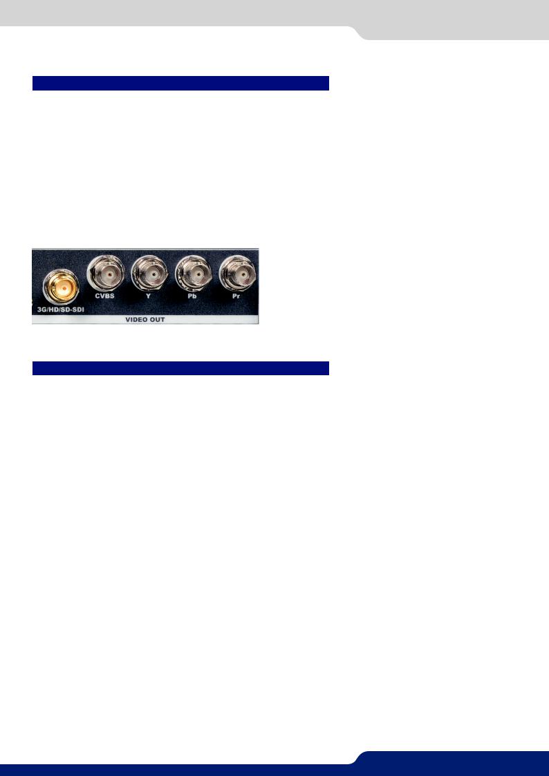
4.7.2 Video output
The Saphyr has one video output.
This video output contains:
-3G/HD/SD-SDI (BNC),
-Analog SDTV (4 × BNC: Composite, YC, YUV, RGBS).
Please see the output formats of the monitoring output:
Output Type |
Format |
Signal |
|
Video Y/C Output |
SDTV |
Analog SDTV |
|
|
|
|
|
Video Y Pb Pr Output |
SDTV |
Analog SDTV |
|
Video RGBSTTL Output |
SDTV |
Analog SDTV |
|
SD-HD-3G-SDI Output |
SDTV |
Digital SDTV |
|
HDTV |
Digital HDTV |
||
|
4.8 Communication specifications
4.8.1 Serial interface
A standard RS232 interface is available through a DB9 female connector:
-It permits controlling the device
-It permits updating the device
Data Rate: 1200 to 115200 Bauds, 8 data bits, 1 stop bit, no parity bit, no flow control by default.
DTR & RTS needed for firmware upgrade.
20
4.8.2 LAN interface
4.8.2 LAN interface
A standard LAN interface is available through a RJ-45 connector
-It permits controlling the device
-It permits transferring configuration
-It permits connectivity with the RCS² application
-It permits updating the device
4.8.2.1 Protocol
Protocol |
Availability |
TCP |
Yes |
|
|
UDP |
Yes |
|
|
4.8.2.2 IP address
Address allocation |
Availability |
Static user defined address |
Yes |
Default IP address: 192.168.2.140
21

4.9 Environmental specifications
4.9 Environmental specifications |
|
Dimensions: |
Weight: |
D 15.75’’x W 19’’ x H 3.46’’ with rack mount and handles |
6,3kg / 13.9 lb |
D 400 mm x W 483 mm x H 88 mm |
(Compatible with a Standard 19” |
|
rack, Height = 2 U) |
D 14.17’’x W 17.3’’ x H 3.46’’ without rack mount and handles
D 360 mm x W 440 mm x H 88 mm
•Cooling air flows from right side to left side.
•Max ambient operating temperature: < 40°C (< 104°F).
•Operating temperature: 0 to +40°C / +32°F to +104°F
•Storage temperature: -40 to +70°C / -40°F to +158°F
•Operating humidity: 10 to 80% (non condensing)
•Input voltage range: 100-240 VAC autosensing, 50/60 Hz
•Typical consumption: 110 W
ELECTRICAL SECURITY:
•IEC 60950-1:2005 (2nd Edition); Am 1:2009
•EN 60950-1:2006 + A1:2010 + A11:2009 + A12:2011, CSA C22.2; National Differences specified in the CB Test Report
•UL listed (Canada & US)
ELECTROMAGNETIC COMPATIBILITY:
•IEC 61000-3-2 (2009)
•IEC 61000-3-3 (2008)
•CISPR22 (2008)
•CISPR24 (2010)
•FCC Part15 of 2012
•IECS-003 of August 2012
ENVIRONMENT:
•RoHS
•WEEE
USE/TRANSPORT:
•ETS 300 019-2-2: Environmental conditions and environmental tests for telecommunications equipment ; Part 2-2 : specification of environmental tests ; Transportation ; Specification T 2.3: Public transportation
•ETS 300 019-2-3: Environmental conditions and environmental tests for telecommunications equipment ; Part2-3:specificationofenvironmentaltests;Stationaryuseatweatherprotectedlocations;Specification T 3.1 and T 3.1 E: Temperature-controlled locations
 If your device should lose power unexpectedly, you may lose any unsaved settings.
22

4.10 HDCP management
4.10 HDCP management
4.10.1 Input HDCP detection
The input HDCP detection is managed by the input components according to HDCP specification.
4.10.2 Output HDCP detection
The Saphyr manages the output HDCP detection according to one of the following criteria:
-Hot plug,
-3-second period attempt.
4.10.3 Keys’ checking
Keys’ checking is performed according to the most restrictive condition among the 2 following ones:
-Every 2 seconds
-Every 128 frames
4.10.4 Output management
HDCP protected content can be displayed only on HDCP protected outputs or displays. Therefore, whenever anHDCPprotectedsourceisplacedintoalayerroutedtoanon-protectedoutput,theSaphyr willnotoutput the protected content on this non-protected output, and the layer will be grayed.
Ifpossible,theSaphyr willallowtodisplayallothernon-protectedcontents,otherwisetheentireoutputwill be muted until the protected content is no longer routed.
4.10.5 HDCP Classification
Class |
Support |
HDCP Receiver |
Yes |
|
|
HDCP Transmitter |
Yes |
|
|
HDCP Repeater |
No |
HDCP Receiver
The HDCP negotiation can be enabled or disabled on all HDCP inputs.
HDCP Transmitter
The HDCP negotiation can be enabled or disabled on all HDCP outputs.
TheSaphyrcanmanageHDCPrepeatersonitsoutputs:upto32displaydevicescanauthenticatesimultaneously on each output.
4.10.6 Status
InordertopermitquickidentificationofalltheHDCPoperationsonthedevice,theSaphyr providesafullset of status summary to help the user with the HDCP management:
- A front panel menu that displays all the general HDCP status of all inputs and outputs
23

5.1.1 Rear panel
 5. CONNECTING THE SAPHYR
5.1 Description
5.1.1 Rear panel
1 |
2 |
3 |
4 |
5 |
6 |
7 |
8 |
9 |
10 |
11 12 |
13 |
14 |
1.Power supply: 100-240 VAC 2.5A 50/60HZ / FUSE F4A 250 VAC; internal, autoswitchable; 110W
2.3G/HD/SD-SDI: inputs #1 to #4
3.S/PDIF: audio inputs #1 to #2
4.MCO male connector: for audio inputs (balanced) #1 to #4
5.MCO male connector: for audio outputs (balanced) #1 to #2
6.S/PDIF: audio outputs #1 to #2
7.Video out connectors: - 1 x BNC-F: 3G/HD/SD-SDI (with audio embedded)
-3 x BNC-F: Y-Cb-Cr
-1 x BNC-F: Composite video PAL/NTSC
8.Universal Analog Computer TV/HDTV: inputs #1 to #4
9.DVI connectors: DVI-D inputs #1 to #4. Capability to receive digital audio signal from HDMI connector via an adaptor (HDMI-compatible)
10.Ethernet plug
11.HDMI connectors: HDMI inputs #3 to #6. Digital audio compliant
12.Communication port: communication port with DB9 female connector
13.Universal Analog Computer TV/HDTV: HD15 outputs #1 to #2
14.DVI connectors: DVI-I outputs #1 to #2. Capability to transmit digital audio signal towards a HDMI connector via an adaptor (HDMI-compatible)
24
5.1.2 Front panel
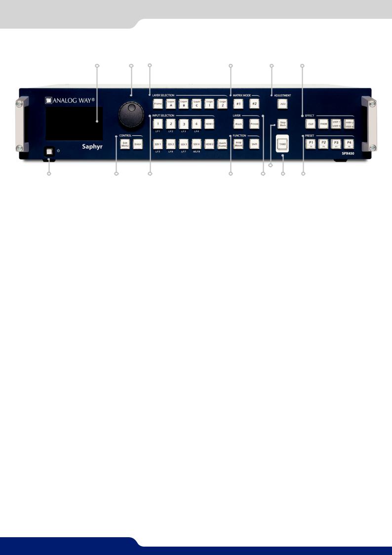
5.1.2 Front panel
1 |
2 |
3 |
4 |
5 |
6 |
|
|
|
|
|
12 |
|
7 |
8 |
9 |
10 |
11 |
13 |
14 |
1.Front panel display: 4-line VFD
2.Menu scroll knob
3.Layer selection: - Frame: un-scaled layer for still frames
-Layer A/B/C: scaled positionable layers for live sources
-Logo 1/2: un-scaled, positionable layer for still logos
4.Matrix mode: #1 to #2: select the output #1 or #2, a layer and a source, then press TAKE
5.Adjustment: adjust layer or logo position, size active layer, zoom active layer
6.Effect: - Cut: select Cut as the current transition type
- |
Fade: select Fade as the current transition type |
-User 1 to 4: select as a customized transition
7.On/Off - Stand-by: hold for 3 seconds for stand-by mode
8.Control: Exit/menu: Home menu or back one level - Enter: validate the menu or command
9.Input selection: - 1 to 4: access source 1 to 4, display frame/logo 1 to 4
-HDMI 1/2: access HDMI 1 or HDMI 2
-SDI 1 to SDI 4: access SDI 1 to SDI 4, display frame/logo 5 to 8
-Quick Frame: allows to quickly display a foreground frame
10.Function: Preview: display Mosaic Preview - Shift: secondary function selection button
11.Layer: - Black: clear the layer
-Freeze: freeze/unfreeze the input selected in the currently selected layer
12.Step Back: recall the last preset into your Preview monitor
13.TAKE: transition the pre-selected sources onto the Program output with the selected effects
14.Preset: P1 to P8: stores and recalls 8 presets available
25
6.1 RCS² requirement
 6. CONTROLLING THE SAPHYR
The Saphyr can be controlled and operated either via the Front Panel, from your computer via the RCS², or via one of our Event Controllers. (Control of the Saphyr can also be integrated into automation and control systems, contact your local technical support for more details.)
6.1 RCS² requirement
The recommended requirements are: |
Operating system: |
- Adobe Air® |
- Windows XP SP3 or above |
- 1Gb Ram |
- Mac OS v10.7 or above |
- 200Mb of free space |
- Ubuntu v10 or above |
- 100Mb Network adaptor or above |
- Linux OS 11 or above |
-1920x1080 optimized screen resolution
-1366x768 as the minimum screen resolution.
For Linux users:
TheRCS²isanAdobe®AIR®applicationthatrequiresthemostrecentversionofthisruntime.AsAdobe®AIR® is no longer supported for desktop Linux distributions, please use a dedicated software such as WINE to use applications designed for Microsoft Windows on your operating system.
1.First, install a Microsoft Windows compatibility layer software on your Linux PC.
2.Then install the Adobe® AIR® last release using your emulator
3.Finally, install the RCS² using your emulator.
You are ready to use the RCS².
6.2 Connecting with the RCS²
The RCS2 is an Adobe Air application that runs on your computer. Before you can connecttoyourdevice,youmustfirstdownloadandinstallAdobeAir,thendownload and install the RCS2 on your computer.
In order to connect the RCS2 to the device, you need to use a LAN connection. Use a crossovercableifyouconnectyourcomputerdirectlytotheunit,orusestraightcablesifyouareconnecting through a switch or hub.
Before switching ON the unit, please plug a LAN cable on the rear panel into the Ethernet port. Then switch ON the unit.
By default, the network settings on the Saphyr are
Default IP Address: 192.168.2.140 Default Subnet Mask: 255.255.255.0
Default port: 10500
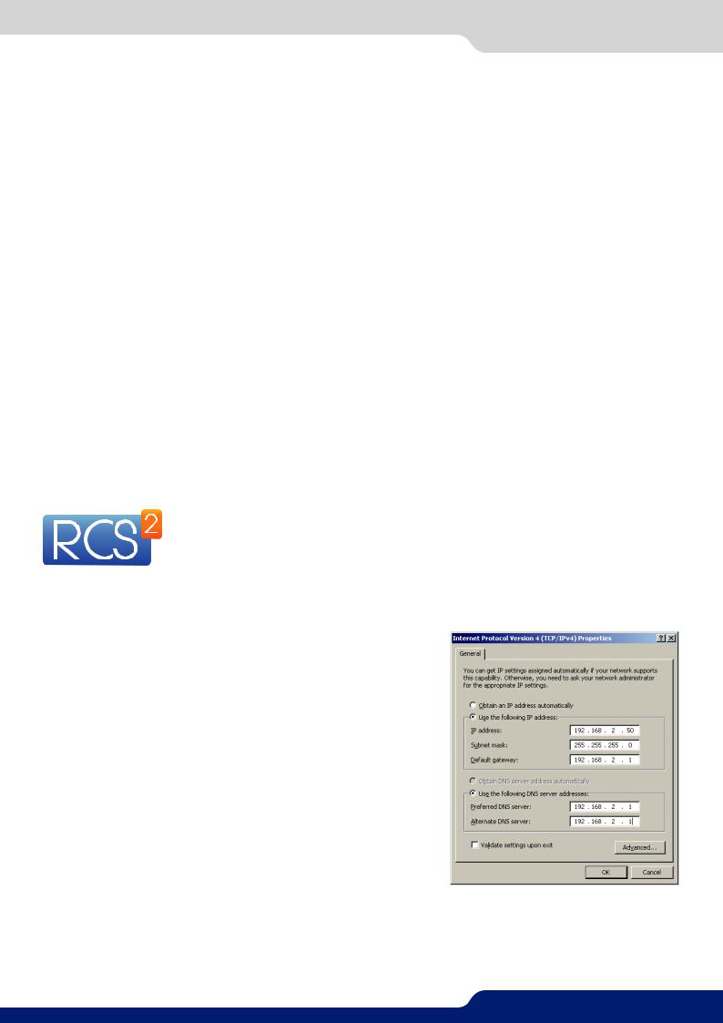
To be able to connect to this address, your computer will need to be configured to use a unique IP address on the same network. If thissetupwillbepartofalargernetworkwithotherdevices,please check with your network administrator before plugging these devices into the network to avoid any IP address conflicts.
Forexample,youcouldassignthefollowingstaticIPaddresstoyour computer:
Example Computer IP address: 192.168.2.50
Example Computer Subnet Mask: 255.255.255.0
To download the Remote Control Software, please visit our website and go into the product section. Then, into the download link, please download the RCS² associated to your product. Install it and then open. Here is the startup screen.
26

6.2 Connecting with the RCS²
Enter the IP address of the device and then the remote port. Click on SET AS DEFAULT if you want the software to remenber your configuration.
Click on Connect to start the connection.
Once connected, you have access to this screen:
In case of difficulties:
-Verify that you are using the correct network cable and that it is free from defects. (Crossover or straight cable as required.)
-Check the IP address of both the device and the computer. It must have a unique IP address on the same network as your Saphyr. You may need to manually configure a static IP address for your computer in your computer’s network configuration.
-You may need to temporarily disable any other networks on the computer, such as turning off the wifi connection.
-Close the RCS².
-Restart the RCS².
Once your computer has established connection, the RCS² control panel will begin to load, and will begin to synchronizewiththedevice. Whenthesmall“Sync”iconatthebottomrightofthedisplayhasturnedgreen, the RCS² software is ready to use.
Some computers use an energy saving mode that turns off the network adaptor during periods of inactivity. To avoid the inconvenience of reconnecting the software during use, please ensure your network adaptor remains active by disabling the energy saving mode.
27

6.3RCS² top menu
6.3RCS² top menu
6.3.1 Setup
The Setup page is where you will review and modify the device configuration, such as output resolutions, input settings, and more.
6.3.2 Edit
TheEditmodeistheplacewhereyouwillmanagepresetcreation.Youwillmakeinputselections,manageyour inputs,adjustthelayerattributessuchassize,position,effect,etc.Youcansaveallyourscreenconfigurations into presets, as well as review and recall them on each individual screen.
6.3.3 Live
The Live mode is the section where you will operate your show. You can quickly recall presets or make input selections, as well as setup a sequence of presets that can run continuously with custom durations, or wait for user interaction.
28
7.1 Operating mode
 7. OPERATING THE SAPHYR FROM THE RCS²
7.1 Operating mode
BeforeyoustartsettingupyourSaphyr forthefirsttime,takesometimetothinkabouthowyouwillbeusing it. The Saphyr offers a choice of two operating modes, which results in a versatile video production tool for live event staging and fixed installation applications.
NOTE: We recommend resetting the device to its default values every time you set up your shows or events.
7.2 Setup
Gotothesetupsectiontostarttosetup your unit. A Setup assistant is available to help you to correctly adjust all basic setups of your unit.
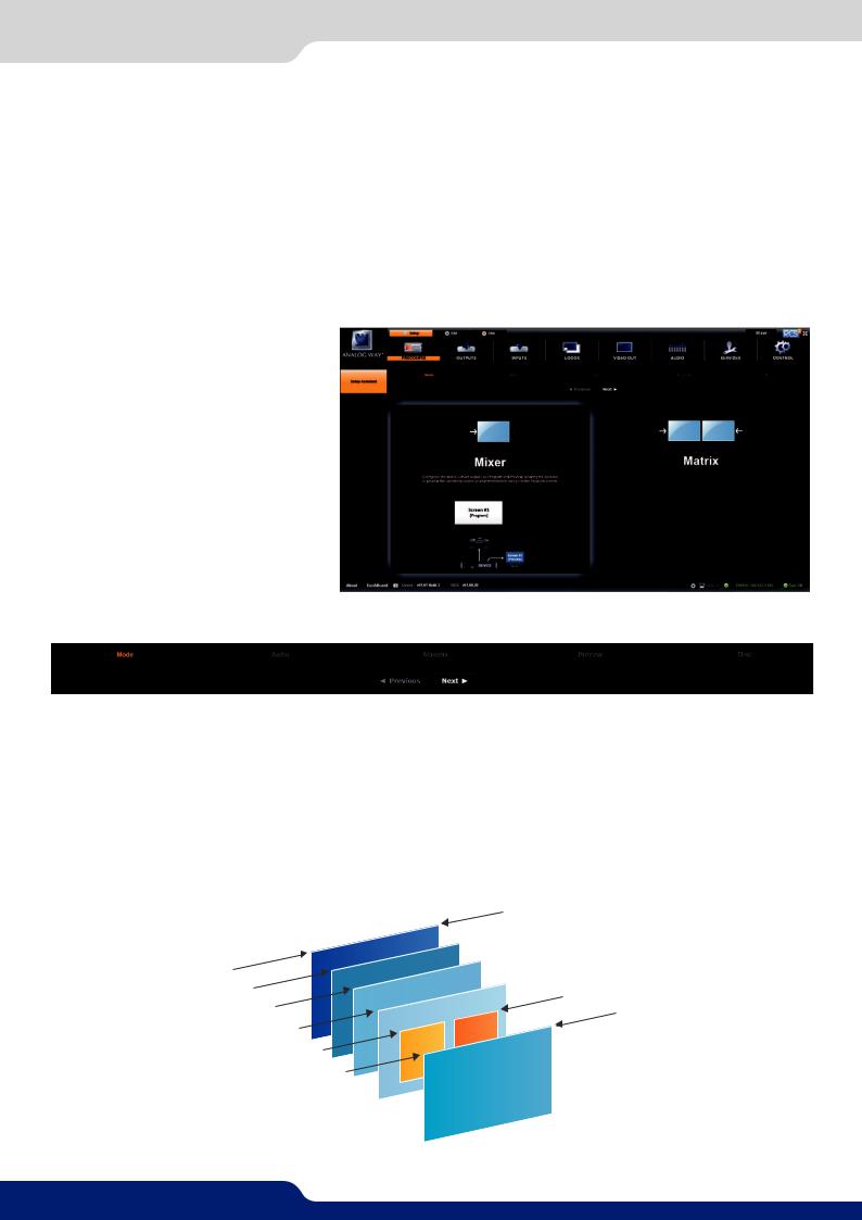
7.2.1 Mode
The device can work in 2 different modes, Mixer mode or Matrix mode.
Mixer mode
ThismodeallowsforasingleSaphyr toseamlesslyswitchanyofits10analog/digitalinputswithanyotherof theinputs,addPIP,titlingorlogoinsertiontotheliveframe,whilepreviewingyoureverymovebeforegoing live,toavoidembarrassingerrorsonyourmainscreen.TheVideooutputoftheSaphyr allowstohaveacopy of the full Main screen at a video resolution for recording or broadcasting.
|
|
|
|
|
|
Background |
|
Frame |
A |
|
|
|
|
Logo |
2 |
Layer |
|
|
|
|
|||
B |
|
|
|
Foreground |
|||
|
|
|
|
|
|||
Layer |
|
|
|
|
|||
|
C |
|
|
|
|
||
|
Layer |
|
|
|
|
||
|
|
|
1 |
|
|
||
|
|
Logo |
|
|
|||
|
|
|
|
|
|||
|
|
Quick |
Frame |
|
|
||
|
|
|
|
|
|
||
29
7.2.2 Audio
Matrix mode
ThismodeturnsyourSaphyr intoatrue10x2scaledmatrix,whilepreservingseamlessswitchingcapabilities. Program1andProgram2outputscanbesettodifferentresolutionsandrates.Switchingbetweenanyofthe inputs can be done with the various effects (Cut, Fade, Slides…) and synchronized on both outputs.
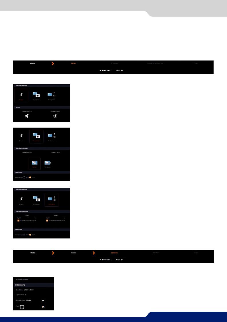
7.2.2 Audio
In this section, you will setup the audio of your device, you have several modes. In all modes, you have the possibility to output the audio in AES3 or SPDIF:
NO AUDIO: the audio of your device is switched off
PRESET MODE: the standard mode of use of the device
You have two possibilities:
•Top layer: the sound on the output will follow the audio input of the top layer.
•Breakaway: when breakaway is activated, the audio on the output is memorized into the preset. A change of preset, changes the audio on the output. A change of content into a video layer has no effect on the audio.
ROUTING MODE: in this configuration, simply choose an audio input to assign it to the output. The audio configuration remains the same during the show.
In this example input1 is on out1 and input 2 is on out 2
7.2.3 Screens
In the screen configuration, you will find the state of your screen. It indicates the screen resolution, the maximum number of layers you can use.
You will find configuration for the Quick Frame and the background color too.
The Quick Frame will be your emergency frame that can be displayed in front of every layer. Here, select the frame slot number to be displayed as the Quick Frame. If you are in Matrix mode, you have 2 screens status.
30
Loading...