


 Loading...
USER MANUAL
LiveCore™ unit
References:
ASC4806, ASC3204, ASC1602, SMX12x4, NXT1604,
LOE048, LOE032, LOE016


 THANK YOU
By following these simple steps you will be able to obtain the most from your powerful LiveCore™ unit and its many features related to the version 02.00.46.
1. TRADEMARKS |
6 |
2. INTRODUCTION |
6 |
3. TERMS AND DEFINITIONS |
7 |
4. HARDWARE SPECIFICATIONS |
8 |
4.1 Safety instructions |
8 |
4.1.1 English |
|
4.1.2 French |
|
4.1.3 Italian |
|
4.1.4 German |
|
4.1.5 Spanish |
|
4.2 Unpacking and inspection |
13 |
4.3 Rack mount information |
13 |
4.4 Cable and adaptor information |
14 |
4.5 Hardware specifications |
14 |
4.5.1 Signal descriptions |
|
4.5.2 Supported video formats |
|
4.5.3 Computer formats |
|
4.5.4 Input Computer formats |
|
4.5.5 Output Computer formats |
|
4.6 Input specifications |
17 |
4.7 Output specifications |
20 |
4.7.1 Standard output |
|
4.7.2 Monitoring output |
|
4.8 Communication specifications |
21 |
4.8.1Serial interface
4.8.2LAN interface
4.8.3Protocol
4.8.4IP address
4.8.5USB host interface
4.8.6Compliance
4.9 Environmental specifications |
23 |
4.9.1Ascender 48
4.9.2Ascender 32
4.9.3Ascender 16
4.9.4SmartMatriX Ultra
4.9.5NeXtage 16
4.9.6LiveCore™ Output Expander - Ref. LOE048, LOE032, LOE016
4.10 HDCP management |
29 |
4.10.1Input HDCP detection
4.10.2Output HDCP detection
4.10.3 Keys’ checking 4.10.4 Output management
4.10.5 HDCP Classification
4.10.6 Status
5. CONNECTING A LIVECORE™ UNIT |
30 |
5.1 Description |
30 |
5.1.1 Rear panel of 4U LiveCore™ unit |
|
5.1.2 Rear panel of 4U LiveCore™ unit - 4K option |
|
5.1.3 Rear panel of NeXtage 16 |
|
5.1.4 Rear panel of NeXtage 16 - 4K option |
|
5.1.5 Rear panel of a LiveCore™ Output Expander |
|
5.1.6 Front panel of Ascender 48 |
|
5.1.7 Front panel of Ascender 32 |
|
5.1.8 Front panel of Ascender 16 |
|
5.1.9 Front panel of SmartMatriX Ultra |
|
5.1.10 Front panel of NeXtage 16 |
|
5.1.11 Front panel of a LiveCore™ Output Expander |
|
6. CONTROLLING A LIVECORE™ UNIT |
41 |
6.1 Web-based RCS requirement |
41 |
6.2 Connecting with the Web RCS |
41 |
6.3 Web RCS top Menu |
42 |
6.3.1 Setup |
|
6.3.2 Edit |
|
6.3.3 Live |
|
7. OPERATING A LIVECORE™ UNIT FROM THE WEB RCS |
43 |
7.1 Functional mode |
43 |
7.2 Display configurations |
43 |
7.2.1 Single device configuration |
|
7.3 Setup |
45 |
7.3.1 Internal rate |
|
7.3.2 Link section |
|
7.3.3 Outputs section
7.3.4 Screens
7.3.5 Inputs section
7.3.6 Logos
7.3.7 Native background section 7.3.8 The miscellaneous section
7.3.9 Output management 7.3.10 Input management
7.3.11 Library management 7.3.12 Logo management 7.3.13 Confidence management 7.3.14 Monitoring management
7.3.15 Blending management
7.3.16 Services management (update) 7.3.17 Control management

7.4 Edit |
73 |
7.4.1Layer management
7.4.2Layer properties
7.4.3Layer settings
7.4.4Layer selection and native background
7.4.5Preset load and save management
7.4.6Logos and Frames management
7.4.7Inputs management
7.4.8Monitoring management
7.5 Live |
86 |
8. OPERATING THROUGH THE FRONT PANEL |
90 |
8.1 Front panel |
90 |
8.1.1Front panel update
8.1.2LCD screen
8.1.3Front panel buttons
8.2 Menu tree |
93 |
|
9. ADDITIONAL REMOTE CONTROL SYSTEMS |
104 |
|
10. ASSEMBLING AND DEVICES COUPLING |
105 |
|
10.1 |
Additive Modularity Linked mode |
105 |
10.2 |
Associative Modularity mode |
106 |
11. MAINTENANCE AND SUPPORT |
107 |
|
11.1 |
Auto Calibration |
107 |
11.2 |
Dashboard (Web RCS) |
108 |
12. APPLICATIONS NOTE AND TIPS |
109 |
|
12.1 HDCP |
109 |
|
13. WARRANTY |
110 |
|
13.1 |
Warranty conditions |
110 |
13.2 |
Repair and return instructions |
110 |
13.3 |
Return conditions |
110 |
14. CONTACT INFORMATION |
111 |
|
15. APPENDICES |
112 |
|

1. Trademarks
 1. TRADEMARKS
ThetermsHDMI,HDMIHigh-DefinitionMultimediaInterfaceandtheHDMILogoaretrademarksorregistered trademarks of HDMI Licensing LLC in the United States and other countries.
 2. INTRODUCTION
Thank you for choosing an Analog Way LiveCore™ unit. Before you start setting up your LiveCore™ unit for the first time, please read through all of the documentation to become familiar with its powerful features. A LiveCore™ unit can be used in several configurations, which results in a versatile video production tool for live event staging and fixed installation applications.
Go on our website to register your product(s) and be notified about new firmware versions:
http://www.analogway.com/en/support/product-registration/
6

3. Terms and definitions
 3. TERMS AND DEFINITIONS
BACKGROUND: a “Background” is a source, typically originating from a computer. A LiveCore™ unit enables you to work with live or still (Frame) background sources — visually in back of all other sources.
LAYER: a “Layer” is an image display element (such as a PIP window, Key, Logo or Background) that has a visual priority — either in front (or in back) of another layer. Depending on the LiveCore™ unit type, up to 6 independent true-seamless scaled layers are available.
PIP: a “PIP” (Picture In Picture) is a picture, typically of reduced size, which is positioned over another background image or other PIPs. PIPs can be repositioned, reduced, enlarged and displayed with borders. PIPs can overlap, depending on their visual priority. A LiveCore™ unit offers various slides, wipes, and fades for dynamic PIP entrances and exits. A “flying” PIP is also possible using vertical, horizontal, diagonal, or curved movement. A PIP is considered a layer.
FRAME:a“Frame”isafullscreenimagewhichisselectedfromoneofthestillFramesloadedontheLiveCore™ unit. Frames are imported from a computer through the Web RCS.
LOGO: a “Logo” is an image imported from a computer, through the Web RCS. It can be keyed, resized and displayed on a layer. A LiveCore™ unit can also resize the logo to be displayed in any size on the screen by resizing and place the related layer.
KEYING: “Key” is an electronic process whereby a video image is electronically superimposed over another sourceorbackground,bydynamicallyremovingaportionofthefirstimage.Forexample,removingallcontent of a certain color (such as green or blue) is called a cutting out either a color (Chroma Key,) and removing content based onor its brightness or luminance levels is called a (Luma Key). Keys are typically used for titles, Logos and special effects. A LiveCore™ unit allows you to key use a live source with Luma or Chroma key effects with green or blue background and to display key it over any other source or sources.
SCREEN: A “Screen” is a destination where the picture will be displayed. For example, it could be a single displayoraprojectionsurfacewhichcanbecomposedofoneorseveraloutputs.Eachscreenmightcomposed with of one or several layers.
SEAMLESS:Clean transition with no glitch or loss of sync while switching between two sources. For example, fading through black to another source is a seamless transition.
TRUE SEAMLESS: Clean seamless transitions with no glitch or freeze between two sources. For example, crossfading from source to source is a true seamless transition.
WEB RCS: Web browser based Remote Control Software used to control, set up, and operate the device.
SOFTEDGE:Soft Edge blending technology is used to compensate for the overlap or covering areawhen two (or more) video projectors are combined to display a continuous content across one screen. The resulting image will appear as though it were a single unified picture.
HARD EDGE: Hard Edge technology is used to display continuous content using to several outputs without any overlap or covering area. The outputs are “side by side”, they don’t overlap or share pixel information. (Opposed to Soft Edge where some parts of the image are simultaneously on several displays.)
CONFIDENCE MONITOR: Confidence monitoring consists on using an output to display a specific content such as another screen, input or combination there-of. You can display one of the main outputs or Preview output content. For example, you might use the confidence monitor to show both the presenter’s laptop input as well as the Program screen on a single display.
7

4.1.1 English
 4. HARDWARE SPECIFICATIONS
4.1 Safety instructions
4.1.1 English
All of the safety and operating instructions should be read before the product is operated and should be maintained for further reference. Please follow all of the warnings on this product and its operating instructions.
•WARNING: To prevent the risk of electric shock and fire, do not expose this device to rain, humidity or intenseheatsources(suchasheatersanddirectsunlight).Slotsandopeningsinthedeviceareprovidedfor ventilation and to avoid overheating. Make sure the device is never placed near a textile surface that could block the openings. Also keep away from excessive dust, vibrations and shocks.
•POWER: Only use the power supply indicated on the device of the power source. Devices equipped with a grounding plug should only be used with a grounding type outlet. In no way should this grounding be modified, avoided or suppressed. Connection of equipment to main supply must be after branch circuit breaker of the building installation.
•POWER CORD: The device is equipped with a detachable power cord, to remove mains disconnect it at appliance coupler.
Caution: The power cord constitutes the only mean to completely disconnect the equipment from the main power.
Apply the following guidelines:
-The equipment connected to the network must have a release system easily accessible and located outside the unit.
-Unplug the power cord; do not pull on the power cord but always on the plug itself.
-The outlet should always be near the device and easily accessible.
-Power supply cords should be routed so that they are not likely to be walked on or pinched by items placed upon or against them.
Ifthepowersupplycordisdamaged,unplugthedevice.Usingthedevicewithadamagedpowersupplycord may expose your device to electric shocks or other hazards. Verify the condition of the power supply cords once in a while. Contact your dealer or service center for replacement if damaged.
•CONNECTIONS: All inputs and outputs (except for the power input) are Safety Extra Low Voltage (SELV) circuits as defined in UL/IEC 60950-1.
•SERVICING: Do not attempt to service this product yourself by opening or removing covers and screws since it may expose your device to electric shocks or other hazards. Refer all problems to qualified service personnel.
•OPENINGS: Never push objects of any kind into this product through the openings. If liquids have been spilled or objects have fallen into the device, unplug it immediately and have it checked by a qualified technician.
8

4.1.2 French
4.1.2 French
Afin de mieux comprendre le fonctionnement de cet appareil nous vous conseillons de bien lire toutes les consignes de sécurité et de fonctionnement avant utilisation. Conservez les instructions de sécurité et de fonctionnement afin de pouvoir les consulter ultérieurement. Respectez toutes les consignes marquées dans la documentation, sur le produit et sur ce document.
•ATTENTION : Afin de prévenir tout risque de choc électrique et d’incendie, ne pas exposer cet appareil à la pluie, à l’humidité ou à des sources de chaleur intense.
•INSTALLATION : Veillez à assurer une circulation d’air suffisante pour éviter toute surchauffe à l’intérieur de l’appareil.Neplacezpasl’appareilsurouàproximitéd’unesurfacetextilesusceptibled’obstruerlesorificesde ventilation.N’installezpasl’appareilàproximitédesourcesdechaleurcommeunradiateurouunepoched’air chaud, ni dans un endroit exposé au rayonnement solaire direct, à des poussières excessives, à des vibrations ou à des chocs mécaniques. Ceci pourrait provoquer un mauvais fonctionnement et un accident.
•ALIMENTATION : Ne faire fonctionner l’appareil qu’avec la source d’alimentation indiquée sur l’appareil. Lesappareilsdoiventêtreobligatoirementconnectéssurunesourceéquipéed’unemiseàlaterreefficace. En aucun cas cette liaison de terre ne devra être modifiée, contournée ou supprimée. Raccordement des équipementsàl’alimentationprincipaledoitêtrepostérieuraudisjoncteurdebranchementdel’installation électrique du bâtiment.
•CORDON D’ALIMENTATION : Les appareils sont équipés d’un cordon d’alimentation détachable, la mise hors tension se fait en débranchant ce cordon de l’appareil.
Attention : Le cordon d’alimentation constitue le seul moyen de débrancher l’appareil totalement de l’alimentation secteur. Pour être certain que l’appareil n’est plus alimenté, ce cordon doit être débranché de la prise murale.
Appliquer les consignes suivantes :
-Lematérielreliéàdemeureauréseau,doitavoirundispositifdesectionnementfacilementaccessible qui doit être incorporé à l’extérieur de l’appareil.
-Débrancher le cordon d’alimentation de la prise murale si vous prévoyez de ne pas utiliser l’appareil pendant quelques jours ou plus.
-Pour débrancher le cordon, tirez-le par la fiche. Ne tirez jamais sur le cordon proprement dit.
-La prise d’alimentation doit se trouver à proximité de l’appareil et être aisément accessible.
-Ne laissez pas tomber le cordon d’alimentation et ne posez pas d’objets lourds dessus.
Si le cordon d’alimentation est endommagé, débranchez-le immédiatement de la prise murale. Il est dangereux de faire fonctionner un appareil avec un cordon endommagé ; un câble abîmé peut provoquer un risque d’incendie ou un choc électrique. Vérifiez le câble d’alimentation de temps en temps. Contactez votre revendeur ou le service après-vente pour un remplacement.
•CONNEXIONS : Toutes les entrées et sorties (exceptée l’entrée d’alimentation) sont des circuits de très basse tension de sécurité (TBTS) tels que définis dans UL / IEC 60950-1.
•RÉPARATION ET MAINTENANCE : L’utilisateur ne doit en aucun cas essayer de procéder aux opérations de dépannage, car l’ouverture des appareils par retrait des capots ou de toutes autres pièces constituant les boîtiers ainsi que le dévissage des vis apparentes à l’extérieur, risquent d’exposer l’utilisateur à des chocs électriques ou autres dangers. Contactez le service après-vente, votre revendeur ou adressez-vous à un personnel qualifié uniquement.
•OUVERTURES ET ORIFICES : Les appareils peuvent comporter des ouvertures (aération, fentes, etc...), veuillez ne jamais y introduire d’objets et ne jamais obstruer ses ouvertures. Si un liquide ou un objet pénètre à l’intérieur de l’appareil, débranchez immédiatement l’appareil et faites-le contrôler par un personnel qualifié avant de le remettre en service.
9

4.1.3Italian
4.1.3Italian
Allo scopo di capire meglio il funzionamento di questa apparecchiatura vi consigliamo di leggere bene tutti i consigli di sicurezza e di funzionamento prima dell’utilizzo. Conservare le istruzioni di sicurezza e di funzionamento al fine di poterle consultare ulteriormente. Seguire tutti i consigli indicati su questo manuale e sull’apparecchiatura.
•ATTENZIONE:Alfinediprevenirequalsiasirischiodishockelettricoed’incendio,nonesporrel’apparecchiatura a pioggia, umidità e a sorgenti di eccessivo calore.
•INSTALLAZIONE: Assicuratevi che vi sia una sufficiente circolazione d’aria per evitare qualsiasi surriscaldamento all’interno dell’apparecchiatura. Non collocare l’apparecchiatura in prossimità o su superfici tessili suscettibili di ostruire il funzionamento della ventilazione. Non installate l’apparecchiatura in prossimità di sorgenti di calore come un radiatore o una fuoruscita d’aria calda, né in un posto esposto direttamenteairaggidelsole,apolvereeccessiva,avibrazionioashockmeccanici.Ciópotrebbeprovocare un erroneo funzionamento e un incidente.
•ALIMENTAZIONE: Far funzionare l’apparecchiatura solo con la sorgente d’alimentazione indicata sull’apparecchiatura.Leapparecchiaturequestedevonoessereobbligatoriamentecollegatesuunasorgente fornitadiunaefficientemessaaterra.Innessuncasoquestocollegamentopotràesseremodificato,sostituito o eliminato. Connessione delle apparecchiature alla rete elettrica deve essere successiva interruttore di circuito dell’impianto dell’edificio
•CAVO DI ALIMENTAZIONE: Il dispositivo è dotato di un cavo di alimentazione removibile, per rimuovere alimentazione scollegarlo dalla Presa.
Attenzione: il cavo di alimentazione è il solo modo di disconnettere l’apparecchio dell’alimentazione. Per assicurarsi che totalemente l’apparecchio non è più collegato, il cavo deve essere disconesso della presa murale.
Seguire le instruzioni seguenti:
-Il materiale collegato a residenza alla rete, deve avere un dispositivo di sezionamento facile da raggiongere eche deve essere inserito all’esterno del apparecchio.
-Disconnetterel’apparecchiaturadallapresamuralesesiprevededinonutilizzarlaperqualchegiorno.
-Per disconnettere il cavo tirare facendo forza sul connettore.
-La presa d’alimentazione deve trovarsi in prossimità dell’apparecchiatura ed essere facilmente accessibile.
-Non far cadere il cavo di alimentazione né appoggiarci sopra degli oggetti pesanti. Se il cavo di alimentazione é danneggiato, spegnere immediatamente l’apparecchiatura.
E’ pericoloso far funzionare questa apparecchiatura con un cavo di alimentazione danneggiato, un cavo graffiatopuóprovocareunrischiodiincendioounoshockelettrico.Verificareilcavodialimentazionespesso. Contattare il vostro rivenditore o il servizio assistenza per una sostituzione.
•CONNESSIONE:Tuttigliingressieleuscite(trannecheperlapotenzainingresso)sonobassissimatensione di sicurezza (SELV) circuiti definiti UL / IEC 60950-1.
•RIPARAZIONI E ASSISTENZA: L’utilizzatore non deve in nessun caso cercare di riparare l’apparecchiatura, poiché con l’apertura del coperchio metallico o di qualsiasi altro pezzo costituente la scatola metallica, nonché svitare le viti che appaiono esteriormente, poiché ció puó provocare all’utilizzatore un rischio di shock elettrico o altri rischi.
•APERTURE DI VENTILAZIONE: Le apparecchiature possono comportare delle aperture di ventilazione, si prega di non introdurre mai oggetti o ostruire le sue fessure. Se un liquido o un oggetto penetra all’interno dell’apparecchiatura, disconnetterla e farla controllare da personale qualificato prima di rimetterla in servizio.
10
4.1.4 German
4.1.4 German
Um den Betrieb dieses Geräts zu verstehen, raten wir Ihnen vor der Inbetriebnahme alle Sicherheits und Betriebsanweisungengenauzulesen.DieseSicherheits-undBetriebsanweisungenfüreinenspäterenGebrauch sicher aufbewahren. Alle in den Unterlagen, an dem Gerät und hier angegebenen Sicherheitsanweisungen einhalten.
•ACHTUNG: um jegliches Risiko eines Stromschlags oder Feuers zu vermeiden, das Gerät nicht Regen, Feuchtigkeit oder intensiven Wärmequellen aussetzen.
•EINBAU: Eine ausreichende Luftzufuhr sicherstellen, um jegliche Überhitzung im Gerät zu vermeiden. Das GerätnichtaufundinNähevonTextiloberflächen,dieBelüftungsöffnungenverschließenkönnen,aufstellen. Das Gerät nicht in Nähe von Wärmequellen, wie z.B. Heizkörper oder Warmluftkappe, aufstellen und es nicht dem direkten Sonnenlicht, übermäßigem Staub, Vibrationen oder mechanischen Stößen aussetzen. Dies kann zu Betriebsstörungen und Unfällen führen.
•STROMVERSORGUNG:Das Gerät nur mit derauf dem Gerät bezeichneteStromquelle betreiben. Gerät mit geerdeter Hauptstromversorgung muss an eine Stromquelle mit effizienter Erdung angeschlossen werden. Diese Erdung darf auf keinen Fall geändert, umgangen oder entfernt werden. Anschluss von Geräten ans Stromnetz muss nach Abzweigschalter des Gebäudes Installation
•NETZKABEL: Das Gerät ist mit einem lösbaren Netzkabel ausgestattet ; um es völlig vom Netz zu trennen, ziehen Sie bitte das Netzkabel aus der Kaltgerätebuchse.
Achtung:DasNetzkabelstelltdieeinzigeMöglichkeitdar,dasGerätvollständigvomNetzanschlusszutrennen. Um sicherzustellen, dass das Gerät nicht mehr versorgt wird, muss dieses Kabel aus der Netzsteckdose ausgesteckt werden.
Bitte beachten Sie die folgenden Hinweise:
-Wenn Geräte dauerhaft am Netz bleiben, müssen sie über eine leicht zugängliche Trennvorrichtung verfügen, die außen am Gerät angebracht sein muss.
-Das Kabel mittels dem Stecker herausziehen. Niemals am Stromkabel selbst ziehen.
-Die Steckdose muß sich in der Nähe des Geräts befinden und leicht zugänglich sein.
-Das Stromkabel nicht fallen lassen und keine schweren Gegenstände auf es stellen.
Wenn das Stromkabel beschädigt ist, das Gerät sofort abschalten. Es ist gefährlich das Gerät mit einem beschädigten Stromkabel zu betreiben; ein abgenutztes Kabel kann zu einem Feuer oder Stromschlag führen. Das Stromkabel regelmäßig untersuchen. Für den Ersatz, wenden Sie sich an Ihren Verkäufer oder Kundendienststelle.
•ANSCHLÜSSE: Alle Eingänge und Ausgänge (mit Ausnahme der Stromversorgung) sind Safety Extra Low Voltage (SELV) Schaltungen wie in UL / IEC 60950-1 definiert.
•REPARATUR UND WARTUNG: Der Benutzer darf keinesfalls versuchen das Gerät selbst zu reparieren, die Öffnung des Geräts durch Abnahme der Abdeckhaube oder jeglichen anderen Teils des Gehäusessowie die Entfernung von außen sichtbaren Schrauben zu Stromschlägen oder anderen Gefahren für den Benutzer führen kann. Wenden Sie sich an Ihren Verkäufer, Ihre Kundendienststelle oder an qualifizierte Fachkräfte.
•ÖFFNUNGEN UND MUNDUNGEN: Die Geräte können über Öffnungen verfügen (Belüftung, Schlitze, usw.). Niemals Gegenstände in die Öffnungen einführen oder die Öffnungen verschließen. Wenn eine Flüssigkeit odereinGegenstandindasGerätgelangt,denSteckerherausziehenundesvoreinerneuenInbetriebnahme von qualifiziertem Fachpersonal überprüfen lassen.
11

4.1.5Spanish
4.1.5Spanish
Paracomprendermejorelfuncionamientodeesteaparato,lerecomendamosqueleacuidadosamentetodas las consignas de seguridad y de funcionamiento del aparato antes de usarlo. Conserve las instrucciones de seguridad y de funcionamiento para que pueda consultarlas posteriormente. Respete todas las consignas indicadas en la documentación, relacionadas con el producto y este documento.
•CUIDADO: Para prevenir cualquier riesgo de choque eléctrico y de incendio, no exponga este aparato a la lluvia, a la humedad ni a fuentes de calorintensas.
•INSTALACIÓN: Cerciórese de que haya una circulación de aire suficiente para evitar cualquier sobrecalentamiento al interior del aparato. No coloque el aparato cerca ni sobre una superficie textil que pudieraobstruirlosorificiosdeventilación.Noinstaleelaparatocercadefuentesdecalorcomoradiadoro bocadeairecaliente,nienunlugarexpuestoalosrayossolaresdirectosoalpolvoexcesivo,alasvibraciones o a los choques mecánicos. Esto podría provocar su mal funcionamiento o un accidente.
•ALIMENTACIÓN: Ponga a funcionar el aparato únicamente con la fuente de alimentación que se indica en el aparato. Los aparatos deben estar conectados obligatoriamente a una fuente equipada con una puesta a tierra eficaz. Por ningún motivo este enlace de tierra deberá ser modificado, cambiado o suprimido. Conexión del equipo a la red eléctrica debe ser posterior del interruptor de circuitos derivados de la instalación del edificio
•CABLE DE CORRIENTE: El equipo se suministra con un cable de corriente si desconectamos el cable dejamos al equipo sin alimentación.
Atención: El cable de alimentación constituye el único medio de desconectar el aparato totalmente de la red eléctrica. Para estar seguro de que el aparato no está más alimentado, este cable debe de ser desconectado de la toma de corriente.
Aplicar las siguientes consignas:
-Elmaterialconectadoaresidenciaalaredinformática,debedetenerundispositivodeseccionamiento fácilmente accesible que debe de ser incorporado al exterior del aparato.
-Desconectar el aparato del enchufe mural si no piensa utilizarlo durante varios días.
-Para desconectar el cable, tire de la clavija. No tire nunca del cable propiamente dicho.
-El enchufe de alimentación debe estar cerca del aparato y ser de fácil acceso.
-No deje caer el cable de alimentación ni coloque objetos pesados encima de él.
Si el cable de alimentación sufriera algún daño, ponga el aparato inmediatamente fuera de tensión. Es peligroso hacer funcionar este aparato con un cable averiado, ya que un cable dañado puede provocar un incendio o un choque eléctrico. Verifique el estado del cable de alimentación de vez en cuando. Póngase en contacto con su distribuidor o con el servicio de posventa si necesita cambiarlo.
•CONEXIONES:Todaslasentradasysalidas(aexcepcióndelaentradadealimentación)sondetensiónextra baja de seguridad (SELV) circuitos definidos en UL / IEC 60950-1.
•REPARACIÓN Y MANTENIMIENTO: Por ningún motivo, el usuario deberá tratar de efectuar operaciones de reparación, ya que si abre los aparatos retirando el capó o cualquier otra pieza que forma parte de las cajasosidestornillalostornillosaparentesexteriores,existeelriesgodeproducirseunaexplosión,choques eléctricos o cualquier otro incidente. Contacte el servicio de posventa, a su distribuidor o dirigirse con personal cualificado únicamente.
•ABERTURAS Y ORIFICIOS: Los aparatos pueden contener aberturas (aireación, ranuras, etc.). Nointroduzca allíningúnobjetoniobstruyanuncaestasaberturas.Siunlíquidoounobjetopenetraalinteriordelaparato, desconéctelo y hágalo revisar por personal cualificado antes de ponerlo nuevamente en servicio.
12

4.2 Unpacking and inspection
4.2 Unpacking and inspection
•1 x LiveCore™ unit
•1 x Power supply cord
•1 x Ethernet cross cable (for device control)
•1 x Web-based Remote Control Software included and hosted on the device
•1 x Rack mount kit
•1 x User manual (PDF version)*
•1 x Quick start guide*
* User manual and Quick start guide are also available on www.analogway.com
CAUTION!
Mounting using only the front rack ears is sufficient for fixed installations. Additional support, such as the rear rack support or slide rails, is required for mobile applications, and recommended for all.
Beforerackingandplugginganyinputsandoutputs,itisadvisedtopowerontheunit.Shouldyouencounter any issue, you must contact immediately your local distributor or dealer, or closest Analog Way technical support offices (see chapter: 14. Contact information).
4.3 Rack mount information
Tabletop mounting: LiveCore™ unit can be used directly on a table; the unit is equipped with 4 handy antislip rubber feet.
Rack mounting: LiveCore™ unit is compatible with a 19” enclosure. Please follow the instructions below to install the device in a 19” rack.
CAUTION: a 4U LiveCore™ unit weighs 42.77LBS (19,4Kg) and 3U weighs 30.86LBS (14Kg). Please provide appropriatesupporttotheframeduringinstallation.First,placeearsoneachsideofthedevice(ref:180469) Place the device in your rack. Attach the device to the rack by using 2 screws through the ears (screws not included).
Additional support, such as the rear rack support or slide rails, is required. LiveCore™ unit is equipped with threaded holes designed for compatibility with a rear rack mount such as ref. 180489. Use the holes in the rear support arm to adjust the length of the rear rack support arm in order to reach the rear rack rail when installed in the rack. Use four M4x10mm screws in the countersunk holes in the rear support bar on both sides of the unit.
A lacing bar is provided with the rack mount kit (ref: 180489). Install it with the M4x10 screws according to your cables position.
Connect all of the cables to the device and attach them to the lacing bar with the help of tie wraps.
IMPORTANT:
-The openings in the front and rear panels of the device are for cooling. Air flows from front to back. Do not cover these openings to avoid cutting air circulation.
-The maximum ambient operating temperature should not exceed 40°C (104°F).
-The rack and all mounted equipment in it must be reliably grounded according to national and/or local electrical standards.
13

4.4 Cable and adaptor information
Dismantlingfronthandlesofthedevicecouldinvalidatewarrantyonafter-salesservicesofyour LiveCore™ unit. It is strongly advised to avoid using front handles as rests for your LiveCore™  unit, they are designed for manipulation purposes only.
If required, front handles of the device can be dismantled, but with caution. The original screws removed must not be reintroduced to their location without handles in place. Substantial damages can occur, including risk of electric shock from the main voltage. Only M4x12mm screws can be used. They are supplied with the unit.
4.4 Cable and adaptor information
A large choice of cables and adaptors are compatible with the LiveCore™ unit. Please refer to the hardware specifications chapter to find the most suitable cables for your operations.
4.5 Hardware specifications
4.5.1 Signal descriptions
For each type of signal, here are the levels and the impedance accepted by the LiveCore™ unit.
Analog SDTV
Type |
Levels |
|
Impedance |
Composite |
0,7 Vpp + 0,3 Vpp |
|
75 Ω |
S. Video |
Y = 0,7 Vpp + 0,3 Vpp |
|
75 Ω |
|
C = 0,7 Vpp |
|
|
|
|
|
|
YUV |
Y = 0,7 Vpp + 0,3 Vpp |
|
|
|
U = 0,7 Vpp |
|
75 Ω |
|
V = 0,7 Vpp |
|
|
RGsB |
R = 0,7 Vpp |
|
|
|
G = 0,7 Vpp + 0,3 Vpp |
|
75 Ω |
|
B = 0,7 Vpp |
|
|
|
R, G, B = 0,7 Vpp |
|
R, G, B = 75 Ω |
RGBS |
S = 0,3 Vpp 75 Ω |
||
or |
|
||
|
|
||
|
S = TTL |
|
|
|
|
|
|
Digital SDTV
Type |
Characteristics |
SD-SDI |
YUV - 10 bits – 4.2.2 - 270 Mb/s |
|
No payload ID management |
|
Only A-level type |
DVI |
RGB ou YUV – 8 bits – 4.4.4 – 16/235 - TMDS |
|
|
HDMI |
RGB or YUV – 10 bits – 4.4.4 or 4.2.2 |
|
– 16/235 – TMDS |
DisplayPort |
RGB or YUV – 10 bits – 4.4.4 or 4.2.2 |
|
– 16/235 – Main Link |
Analog EDTV
Type |
Levels |
|
Impedance |
YUV |
Y = 0,7 Vpp + 0,3 Vpp |
|
|
|
U = 0,7 Vpp |
|
75 Ω |
|
V = 0,7 Vpp |
|
|
RGsB |
R = 0,7 Vpp |
|
|
|
G = 0,7 Vpp + 0,3 Vpp |
|
75 Ω |
|
B = 0,7 Vpp |
|
|
|
R, G, B = 0,7 Vpp |
|
R, G, B = 75 Ω |
|
|
|
|
RGBS |
S = 0,3 Vpp 75 Ω |
||
or |
|
||
|
|
||
|
S = TTL |
|
|
Digital EDTV
Type |
Characteristics |
DVI |
RGB or YUV – 8 bits – 4.4.4 – 16/235 - TMDS |
|
|
HDMI |
RGB or YUV – 10 bits – 4.4.4 or 4.2.2 |
|
– 16/235 – TMDS |
DisplayPort |
RGB or YUV – 10 bits – 4.4.4 or 4.2.2 |
|
– 16/235 – Main Link |
14

Analog HDTV
These formats are compatible with bi-level and trilevel sync on 1 or 3 wires.
Type |
Levels |
Impedance |
YUV |
Y = 0,7 Vpp ±0,3 Vpp |
|
|
U = 0,7 Vpp ±0,3 Vpp |
75 Ω |
|
V = 0,7 Vpp ±0,3 Vpp |
|
RGsB |
R = 0,7 Vpp ±0,3 Vpp |
|
|
G = 0,7 Vpp ±0,3 Vpp |
75 Ω |
|
B = 0,7 Vpp ±0,3 Vpp |
|
4.4 Cable and adaptator information
Digital HDTV
Type |
Characteristics |
HD-SDI |
YUV - 10 bits – 4.2.2 – 1,485Gb/s and |
|
1,485/1.001Gb/s |
|
Only A-level type |
|
Input and output payload ID management |
|
for HDTV format only |
|
|
3G-SDI |
YUV - 10 bits – 4.2.2 – 2,97Gb/s and |
|
2,97/1.001Gb/s |
|
Only A-level type |
|
Input and output payload ID management |
|
for HDTV format only |
DVI |
RGB or YUV – 8 bits – 4.4.4 – 16/235 - TMDS |
|
|
DisplayPort |
RGB or YUV – 8 bits – 4.4.4 or 4.2.2 |
|
– 16/235 – Main Link |
HDMI |
RGB or YUV – 10 bits – 4.4.4 or 4.2.2 |
|
– 16/235 – TMDS |
Analog computer
Type |
Levels |
Impedance |
|
RGsB |
R = 0,7 Vpp |
|
|
|
G = 0,7 Vpp + 0,3 Vpp |
75 Ω |
|
|
B = 0,7 Vpp |
|
|
RGBS |
R, G, B = 0,7 Vpp |
R, G, B = 75 Ω |
|
|
|
||
S = 0,3 Vpp 75Ω or S = TTL |
|||
|
|||
|
|
|
|
RGBHV |
R, G, B = 0,7 Vpp |
R, G, B = 75 Ω |
|
H = TTL and V = TTL |
|||
|
|||
|
|
|
|
Digital UHDTV
Type |
Characteristics |
HDMI® |
RGB or YUV – 8 bits – 4.4.4 or 4.2.2 |
|
– 0/255 – TMDS |
Digital computer
Type |
Characteristics |
DVI |
RGB – 8 bits – 4.4.4 – 0/255 - TMDS |
HDMI® |
RGB or YUV – 10 bits – 4.4.4 or 4.2.2 |
|
– 0/255 – TMDS |
DiplayPort |
RGB or YUV – 10 bits – 4.4.4 or 4.2.2 |
|
– 0/255 – Main Link |
15

4.5.2Supported video formats
4.5.2Supported video formats
A LiveCore™ unit can support all the following video formats:
SDTV formats
Standard |
Size |
Vertical frequency |
Horizontal frequency |
NTSC |
525/480i |
59.94Hz/60Hz |
15,735 KHz |
|
|
|
|
PAL |
625/576i |
50Hz |
15.625 KHz |
SECAM |
625/576i |
50Hz |
15.625 KHz |
|
|
|
|
EDTV formats
Standard |
Size |
Vertical frequency |
Horizontal frequency |
|
|
|
|
480p |
525/480p |
59.94Hz/60Hz |
31.47 KHz |
|
|
|
|
576p |
625/576p |
50Hz |
31.25 KHz |
HDTV formats
Standard |
Size |
Vertical frequency |
720p |
1280 x 720 |
23.97Hz/24Hz/25Hz/29,97Hz/30Hz/50Hz/59.94Hz/60Hz |
|
|
|
1035i |
1920 x 1035 |
59.94Hz/60Hz |
|
|
|
1080i |
1920 x 1080 |
50Hz/59.94Hz/60Hz |
1080sF |
1920 x 1080 |
50Hz/59.94Hz/60Hz |
|
|
|
1080p |
1920 x 1080 |
23.97Hz/24Hz/25Hz/29,97Hz/30Hz/50Hz/59.94Hz/60Hz |
|
|
|
Cinema formats
Format |
Size |
Vertical frequency |
DCDM |
2048 x 1080 |
24Hz |
4K 4:4:4 |
4096 x 2160 |
23.97Hz/24Hz/25Hz/29,97Hz/30Hz |
|
|
|
4K 4:2:0* |
4096 x 2160 |
50Hz/59,94Hz/60Hz |
|
|
|
*These 4:2:0 formats are only available on the outputs.
UHDTV formats
Standard |
Size |
Vertical frequency |
|
|
|
2160p 4:4:4 |
3840 x 2160 |
23.97Hz/24Hz/25Hz/29,97Hz/30Hz |
2160p 4:2:0 |
3840 x 2160 |
50Hz/59,94Hz/60Hz |
4.5.3 Computer formats
Important: The maximum pixel clock frequency is 165 MHz. This corresponds to 1600x1200 @ 60 Hz, for single link. For dual and 4K resolutions, the maximum pixel clock frequency is 330 MHz.
4.5.4 Input Computer formats
The inputs of a LiveCore™ unit support GTF (version 1.1), CVT (version 1.1) and DMT (version 1.0 rev 12) standards.Allothersnon-standardformatsaresupportedviathecustomformatcapabilityoftheframework.
16

4.5.5 Output computer formats
4.5.5 Output Computer formats
The outputs of a LiveCore™ unit support GTF (version 1.1), CVT (version 1.1) and DMT (version 1.0 rev 12) standards. Other non-standard formats are supported via the custom format capability of the framework. A LiveCore™ unit offers a list of pre-defined output formats. The list of output formats is always displayed from increasing number of pixels per line and then number of lines.
Format |
Size |
Aspect ratio |
Frequency |
|
50 Hz |
60 Hz |
|||
VGA |
640x480 |
4/3 |
No |
Yes |
WVGA |
848x480 |
16/9 |
No |
Yes |
SVGA |
800x600 |
4/3 |
No |
Yes |
720p |
1280x720 |
16/9 |
Yes |
Yes |
XGA |
1024x768 |
4/3 |
Yes |
Yes |
WXGA |
1280x768 |
5/3 |
Yes |
Yes |
SWXGA |
1360x768 |
16/9 |
Yes |
Yes |
1366x768 |
1366x768 |
16/9 |
Yes |
Yes |
WXGA2 |
1280x800 |
16/9 |
Yes |
Yes |
SWXGAP |
1366x800 |
5/3 |
Yes |
Yes |
XGA+ |
1152x864 |
4/3 |
Yes |
Yes |
WXGA+ |
1440x900 |
16/10 |
Yes |
Yes |
HD+ |
1600x900 |
16/9 |
Yes |
Yes |
SXGA- |
1280x960 |
4/3 |
Yes |
Yes |
WXGA+ |
1440x960 |
3/2 |
Yes |
Yes |
SXGA |
1280x1024 |
5/4 |
Yes |
Yes |
|
1360x1024 |
4/3 |
Yes |
Yes |
SXGAP |
1400x1050 |
5/3 |
Yes |
Yes |
WSXGAP |
1680x1050 |
16/9 |
Yes |
Yes |
1080p |
1920x1080 |
16/9 |
Yes |
Yes |
*Dual-Link format
Format |
Size |
Aspect ratio |
Frequency |
|
50 Hz |
60 Hz |
|||
2K |
2048x1080 |
17/9 |
Yes |
Yes |
UW-UXGA* |
2560x1080 |
21/9 |
Yes |
Yes |
QWXGA |
2048x1152 |
16/9 |
Yes |
Yes |
UXGA |
1600x1200 |
4/3 |
Yes |
Yes |
WUXGA |
1920x1200 |
16/9 |
Yes |
Yes |
WQHD* |
2560x1440 |
16/9 |
Yes |
Yes |
QXGA* |
2048x1536 |
4/3 |
Yes |
Yes |
WQXGA* |
2560x1600 |
16/10 |
Yes |
Yes |
4.6 Input specifications
A LiveCore™ unit offers two or three input module cards. Each input module card contains 4 inputs. Each input is composed of several plugs. A plug corresponds to a socket on the rear panel.
The following types of plugs are available on the rear panel:
-4-Lanes DisplayPort in version 1.1a (can accept a Dual-Link DVI input via a non-supplied active adaptor)
-HDMI
-Single DVI-I / Dual-Link DVI-D (DVI-I connector),
-3G/HD/SD-SDI (BNC),
-Universal Analog (HD-15)
17

4.6 Input specifications
For devices with the optional 4K:
A LiveCore™ unit uses an HDMI plug with a standard mounting screw above the connector. Please see the diagram below.
This hole is occupied by a Torx10 screw when you receive the unit. If desired, this screw can be removed and replaced by a compatible aftermarket HDMI plug locking mechanism to ensure a secure HDMI connection.
M3x0,5 mm
27 mm
This hole is used by a TX10 screw when you receive the unit, if you wish to use an HDMI cable with a security fixing screw you can take this screw off and use your own in order to insure good fixing of your HDMI plug.
Please take a look at the accepted format regarding the input plug type:
Plug Type |
Formats |
Signals |
Universal Analog Input |
SDTV - EDTV - HDTV - Computer |
Analog SDTV - Analog EDTV - Analog HDTV - Analog Computer |
DVI-A Input |
SDTV - EDTV - HDTV - Computer |
Analog SDTV - Analog EDTV - Analog HDTV - Analog Computer |
|
|
|
DVI-D Input |
SDTV - EDTV - HDTV - Computer |
Digital SDTV - Digital EDTV - Digital HDTV - Digital Computer |
DisplayPort Input |
SDTV - EDTV - HDTV - Computer |
Digital SDTV - Digital EDTV - Digital HDTV - Digital Computer |
HDMI Input |
SDTV - EDTV - HDTV - Computer |
Digital SDTV - Digital EDTV - Digital HDTV - Digital Computer |
|
|
|
HDMI 4K input* |
4K DCI - UHDTV - SDTV - EDTV - HDTV |
Digital SDTV - Digital EDTV - Digital HDTV - Digital UHDTV |
3G/HD/SD-SDI Input |
SDTV - HDTV |
Digital SDTV - Digital HDTV |
*only available with the 4K option
WARNING: Only the video signal is processed for the HDMI®, 3G/HD/SD-SDI and DisplayPort inputs; the embedded audio is not processed. All other HDMI® features such as: HDMI Ethernet Channel, Audio Return Channel, 3D, 4K, Content Type, Deep Color and x.v.Color are NOT supported.
Each input can display only one active plug at a time. It is instantly available on the device and can be displayed simultaneously on many layers or outputs, with different sizes and positions. Each input can be used independently except with the Dual-Link and Dual-Head configuration which are using two inputs.
18

4.6 Input specifications
Standard |
Size |
HD-15 |
3G-SDI |
HDMI |
2-Lanes |
4-Lanes3 Dis- |
Single-Link |
Dual-Link |
|
DisplayPort |
playPort |
DVI-I |
DVI-D |
||||||
|
|
|
|
|
|||||
NTSC |
525/480i |
Yes |
Yes |
Yes |
No |
No |
No |
No |
|
PAL |
625/576i |
Yes |
Yes |
Yes |
No |
No |
No |
No |
|
SECAM |
625/576i |
Yes |
Yes |
Yes |
No |
No |
No |
No |
|
480p |
525/480p |
Yes |
No |
Yes |
Yes |
Yes |
Yes |
Yes |
|
576p |
625/576p |
Yes |
No |
Yes |
Yes |
Yes |
Yes |
Yes |
|
720p |
1280x720 |
Yes |
Yes |
Yes |
Yes |
Yes |
Yes |
Yes |
|
1035i |
1920x1035 |
Yes |
Yes |
Yes |
Yes |
Yes |
Yes |
Yes |
|
1080i |
1920x1080 |
Yes |
Yes |
Yes |
Yes |
Yes |
Yes |
Yes |
|
1080p |
1920x1080 |
Yes |
Yes |
Yes |
Yes |
Yes |
Yes |
Yes |
|
1080sF |
1920x1080 |
Yes |
Yes |
Yes |
Yes |
Yes |
Yes |
Yes |
|
1080p |
1920x1080 |
Yes |
Yes |
Yes |
Yes |
Yes |
Yes |
Yes |
|
DCDM |
2048x1080 |
No |
Yes |
No |
No |
No |
No |
No |
|
VGA |
640x480 |
Yes |
No |
Yes |
Yes |
Yes |
Yes |
Yes |
|
800x480 |
800x480 |
Yes |
No |
Yes |
Yes |
Yes |
Yes |
Yes |
|
WVGA |
848x480 |
Yes |
No |
Yes |
Yes |
Yes |
Yes |
Yes |
|
SVGA |
800x600 |
Yes |
No |
Yes |
Yes |
Yes |
Yes |
Yes |
|
1280x600 |
1280x600 |
Yes |
No |
Yes |
Yes |
Yes |
Yes |
Yes |
|
720p RGB |
1280x720 |
Yes |
No |
Yes |
Yes |
Yes |
Yes |
Yes |
|
XGA |
1024x768 |
Yes |
No |
Yes |
Yes |
Yes |
Yes |
Yes |
|
WXGA |
1280x768 |
Yes |
No |
Yes |
Yes |
Yes |
Yes |
Yes |
|
SWXGA |
1360x768 |
Yes |
No |
Yes |
Yes |
Yes |
Yes |
Yes |
|
1366x768 |
1366x768 |
Yes |
No |
Yes |
Yes |
Yes |
Yes |
Yes |
|
800p RGB |
1280x800 |
Yes |
No |
Yes |
Yes |
Yes |
Yes |
Yes |
|
SWXGA+ |
1366x800 |
Yes |
No |
Yes |
Yes |
Yes |
Yes |
Yes |
|
1152x864 |
1152x864 |
Yes |
No |
Yes |
Yes |
Yes |
Yes |
Yes |
|
900p RGB |
1440x900 |
Yes |
No |
Yes |
Yes |
Yes |
Yes |
Yes |
|
1600x900 |
1600x900 |
Yes |
No |
Yes |
Yes |
Yes |
Yes |
Yes |
|
960p RGB |
1280x960 |
Yes |
No |
Yes |
Yes |
Yes |
Yes |
Yes |
|
SXGA |
1280x1024 |
Yes |
No |
Yes |
Yes |
Yes |
Yes |
Yes |
|
1360x1024 |
1360x1024 |
Yes |
No |
Yes |
Yes |
Yes |
Yes |
Yes |
|
DILA4/3 |
1364x1024 |
Yes |
No |
Yes |
Yes |
Yes |
Yes |
Yes |
|
SXGA+ |
1400x1050 |
Yes |
No |
Yes |
Yes |
Yes |
Yes |
Yes |
|
WSXGA+ |
1680x1050 |
Yes |
No |
Yes |
Yes |
Yes |
Yes |
Yes |
|
1080p RGB |
1920x1080 |
Yes1 |
No |
Yes |
Yes |
Yes |
Yes |
Yes |
|
2K |
2048x1080 |
Yes1 |
No |
Yes |
Yes |
Yes |
Yes |
Yes |
|
UXGA |
1600x1200 |
Yes |
No |
Yes |
Yes |
Yes |
Yes |
Yes |
|
WUXGA |
1920x1200 |
Yes1 |
No |
Yes |
Yes |
Yes |
Yes |
Yes |
|
1920x1440 |
1920x1440 |
Undersampled2 |
No |
No |
No |
Yes |
No |
Yes |
|
QXGA4 |
2048x1536 |
Undersampled2 |
No |
No |
No |
Yes |
No |
Yes |
|
2560x1080 |
2560x1080 |
No |
No |
No |
No |
Yes |
No |
Yes |
|
2560x1440 |
2560x1440 |
No |
No |
No |
No |
No |
No |
Yes |
|
WQXGA4 |
2560x1600 |
No |
No |
No |
No |
Yes |
No |
Yes |
Notes:
1)Reduced Blanking
2)The signal is under-sampled: the image cannot be reproduced on 1:1 scaling (i.e. a 1920x1440 signal is under-sampled and then stretched horizontally to fit on a 1920x1440 image. The quality is not as good as it could be with a properly sampled signal)
3)4-Lanes DisplayPort in version 1.1a (accept a Dual-Link DVI input via a non-supplied active adaptor)
4)Dual-Link format
5)4K format, only available with the 4K option
19
4.7.2 Monitoring output
4.7 Output specifications
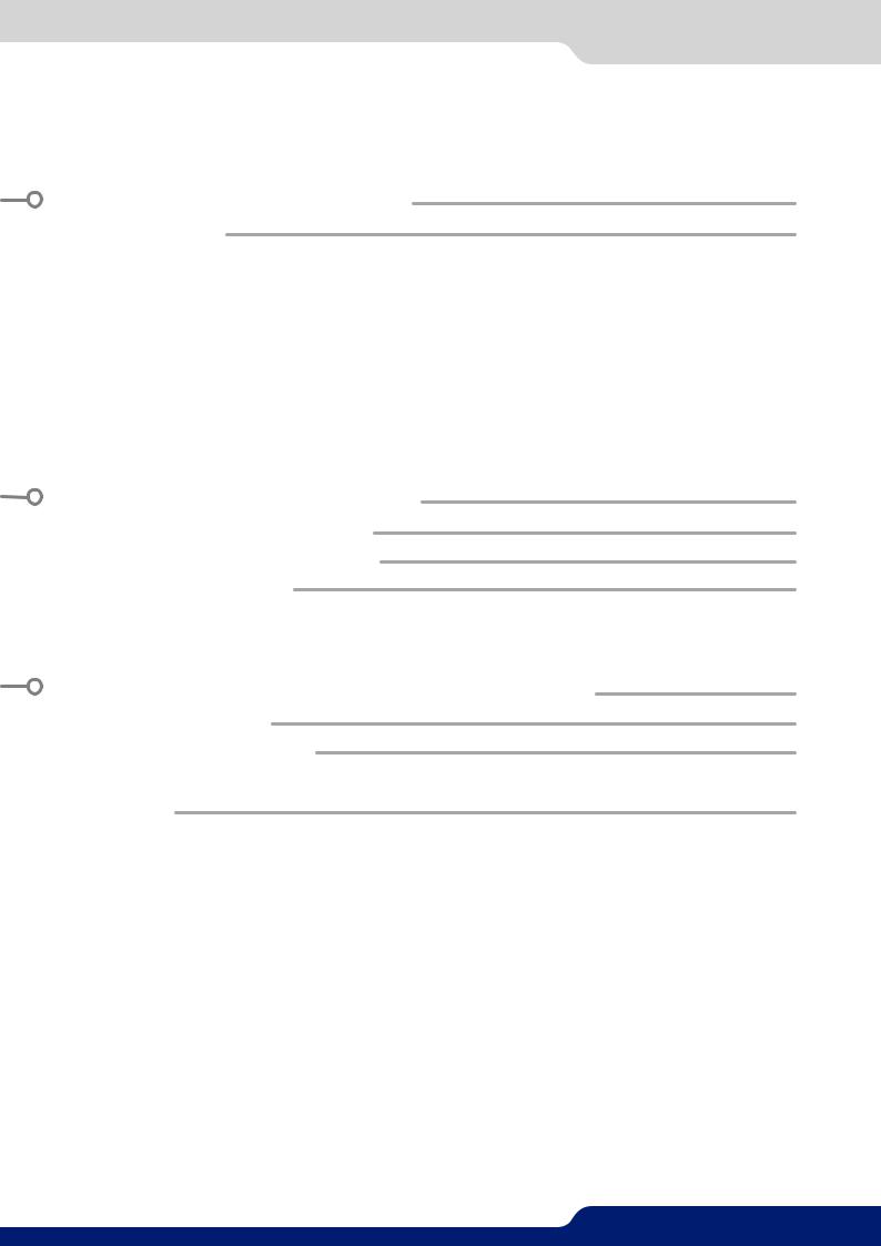
4.7.1 Standard output
A LiveCore™ unit has two standard output modules.
The standard module contains two outputs with the following plugs:
-3G/HD/SD-SDI (two clone outputs via 1 BNC and 1 dual video optical SFP module),
-Analog Computer/Video (HD15),
-DVI:Dual-LinkDVI-Iforoutput#1andSingle-LinkDVI-Ion output #2 (both with DVI-I connectors).
*
* For devices with the optional 4K: DVI-I HDMI 4K
When using the standard output module for a dual-link DVI connection, connect the display to output #1. Output #2 will not be available when outputting a Dual-link DVI connection.
Please see the formats available on the output:
Output Type |
Format |
Signal |
|
Analog Computer/Video Ouput |
HDTV |
Analog HDTV |
|
Computer |
Analog Computer |
||
|
|||
DVI-I Dual-Link Output |
HDTV |
Digital HDTV |
|
Computer |
Digital Computer |
||
|
|||
3G-SDI Output |
HDTV |
Digital HDTV |
|
Dual Video Optical SFP Module |
HDTV |
Digital HDTV |
|
|
|
|
Please note that SDTV and EDTV are not available on the standard output module and require the monitoring output module.
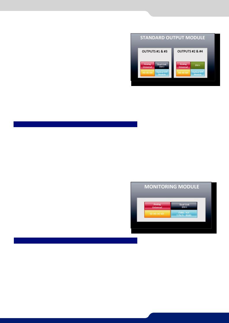
4.7.2 Monitoring output
A LiveCore™ unit has one monitoring output module.
This module contains one output with the following plugs:
-3G/HD/SD-SDI (2 x BNC),
-Analog Computer/Video (HD15),
-Dual-Link DVI-I (DVI-I),
-Analog SDTV (4 × BNC: Composite, YC, YUV, RGBS).
Please see the output formats of the monitoring output:
Output Type |
Format |
Signal |
|
Video Y/C Output |
SDTV |
Analog SDTV |
|
|
|
|
|
Video Y Pb Pr Output |
SDTV |
Analog SDTV |
|
Video RGBSTTL Output |
SDTV |
Analog SDTV |
|
|
|
|
|
|
SDTV |
Analog SDTV |
|
Analog Computer / Video Output |
EDTV |
Analog EDTV |
|
HDTV |
Analog HDTV |
||
|
|||
|
Computer |
Analog Computer |
|
|
|
|
|
|
SDTV |
Digital SDTV |
|
DVI-I Dual-Link Output |
EDTV |
Digital EDTV |
|
HDTV |
Digital HDTV |
||
|
|||
|
Computer |
Digital Computer |
|
|
|
|
|
SD-HD-3G-SDI Output |
SDTV |
Digital SDTV |
|
HDTV |
Digital HDTV |
||
|
20
4.8.5 USB host interface
4.8 Communication specifications
4.8.1 Serial interface
A RS-232 compliant link is available through a DB-9 connector. It is used for reserved for factory usage and also communicating with the SPU001 external power module.
4.8.2 LAN interface
Link |
Baud rate |
RS-232 Link |
Will depend on debug application |
A standard LAN interface is available through a RJ-45 connector (at 10/100/1000 Mbps)
-It permits controlling and updating the device
-It permits transferring Frames and Logos
-It permits transferring configuration and log files
-It permits connectivity with a web-client for the Web RCS application
4.8.3 Protocol |
|
|
|
The LiveCore™ unit can be controlled by third party |
|
|
|
Protocol |
Availability |
||
devices using dedicated Crestron, AMX modules or by |
|||
TCP |
Yes |
||
sending ASCI strings which are documented in the TPP. |
|||
|
|
||
UDP |
Yes |
||
For more information, see the «Programmer’s Guide» |
|||
|
|
||
section on our website. |
|
|
|
4.8.4 IP address |
|
|
|
The default network configuration for the LiveCore™ |
|
|
|
Address allocation |
Availability |
||
devices is: |
Static user defined address |
Yes |
|
IP address: 192.168.2.140 |
|
|
|
DHCP |
Yes |
||
Subnet mask: 255.255.255.0 |
|||
|
|
||
|
|
||
Gateway: 192.168.2.1 |
|
|
|
For more information about connecting to the device, please see chapter 6. |
|
||
4.8.5 USB host interface
In order to support a USB Host interface, a LiveCore™ unit is equipped with five A-type USB connectors:
-One is located on the front panel,
-Four are located on the rear panel.
It is used to transfer updates.
21

4.8.6Compliance
4.8.6Compliance
This interface is fully compliant with USB 2.0 High Speed specification (up to 480 Mbps).
1 |
2 |
3 |
4 |
SUPPORTED CLASSES
Class |
Availability |
SCSI Mass Storage |
Yes |
Pin number |
Function |
1 |
5V |
2 |
D- |
|
|
3 |
D+ |
4 |
Ground |
22

4.9.1 Ascender 48
4.9 Environmental specifications
4.9.1 Ascender 48
Dimensions: |
Weight: |
W 482 x D 552 x H 177 mm with rack mount and handles |
19,4 kg / 42.77 lbs |
19”W x 23.73”D x 6.97”H |
(Compatible with a Standard |
|
19” rack, Height = 4 U) |
W 445 x D 552 x H 177 mm without rack mount and handles
17.52”W x 23.73”D x 6.97”H
•Cooling air flows from front side to rear.
•Max ambient operating temperature: < 40°C (< 104°F).
•Operating temperature: 0 to +40°C / +32°F to +104°F
•Storage temperature: -40 to +70°C / -40°F to +158°F
•Operating humidity: 10 to 80% (non condensing)
•Input voltage range: 100-240 VAC autosensing, 50/60 Hz
•Typical consumption: Ascender 48: 405 W
ELECTRICAL SECURITY:
•IEC 60950-1:2005 (2nd Edition); Am 1:2009
•EN 60950-1:2006 + A1:2010 + A11:2009 + A12:2011, CSA C22.2; National Differences specified in the CB Test Report
•UL listed (Canada & US)
ELECTROMAGNETIC COMPATIBILITY:
•IEC 61000-3-2 (2009)
•IEC 61000-3-3 (2008)
•CISPR22 (2008)
•CISPR24 (2010)
•FCC Part15 of 2012
•IECS-003 of August 2012
ENVIRONMENT:
•RoHS
•WEEE
USE/TRANSPORT:
•ETS 300 019-2-2: Environmental conditions and environmental tests for telecommunications equipment ; Part 2-2 : specification of environmental tests ; Transportation ; Specification T 2.3: Public transportation
•ETS 300 019-2-3: Environmental conditions and environmental tests for telecommunications equipment ; Part2-3:specificationofenvironmentaltests;Stationaryuseatweatherprotectedlocations;Specification T 3.1 and T 3.1 E: Temperature-controlled locations
 If your device should lose power unexpectedly, you may lose any unsaved settings.
23

4.9.2 Ascender 32
4.9.2 Ascender 32
Dimensions: |
Weight: |
W 482 x D 552 x H 177 mm with rack mount and handles |
19,4 kg / 42.77 lbs |
19”W x 23.73”D x 6.97”H |
(Compatible with a Standard |
|
19” rack, Height = 4 U) |
W 445 x D 552 x H 177 mm without rack mount and handles
17.52”W x 23.73”D x 6.97”H
•Cooling air flows from front side to rear.
•Max ambient operating temperature: < 40°C (< 104°F).
•Operating temperature: 0 to +40°C / +32°F to +104°F
•Storage temperature: -40 to +70°C / -40°F to +158°F
•Operating humidity: 10 to 80% (non condensing)
•Input voltage range: 100-240 VAC autosensing, 50/60 Hz
•Typical consumption: Ascender 32: 345 W
ELECTRICAL SECURITY:
•IEC 60950-1:2005 (2nd Edition); Am 1:2009
•EN 60950-1:2006 + A1:2010 + A11:2009 + A12:2011, CSA C22.2; National Differences specified in the CB Test Report
•UL listed (Canada & US)
ELECTROMAGNETIC COMPATIBILITY:
•IEC 61000-3-2 (2009)
•IEC 61000-3-3 (2008)
•CISPR22 (2008)
•CISPR24 (2010)
•FCC Part15 of 2012
•IECS-003 of August 2012
ENVIRONMENT:
•RoHS
•WEEE
USE/TRANSPORT:
•ETS 300 019-2-2: Environmental conditions and environmental tests for telecommunications equipment ; Part 2-2 : specification of environmental tests ; Transportation ; Specification T 2.3: Public transportation
•ETS 300 019-2-3: Environmental conditions and environmental tests for telecommunications equipment ; Part2-3:specificationofenvironmentaltests;Stationaryuseatweatherprotectedlocations;Specification T 3.1 and T 3.1 E: Temperature-controlled locations
 If your device should lose power unexpectedly, you may lose any unsaved settings.
24

4.9.3 Ascender 16
4.9.3 Ascender 16
Dimensions: |
Weight: |
W 482 x D 544 x H 177 mm with rack mount and handles |
19 kg / 41.89 lbs |
19”W x 23.73”D x 6.97”H |
(Compatible with a Standard |
|
19” rack, Height = 4 U) |
W 445 x D 544 x H 177 mm without rack mount and handles
17.52”W x 23.73”D x 6.97”H
•Cooling air flows from front side to rear.
•Max ambient operating temperature: < 40°C (< 104°F).
•Operating temperature: 0 to +40°C / +32°F to +104°F
•Storage temperature: -40 to +70°C / -40°F to +158°F
•Operating humidity: 10 to 80% (non condensing)
•Input voltage range: 100-240 VAC autosensing, 50/60 Hz
•Typical consumption: Ascender 16: 285 W
ELECTRICAL SECURITY:
•IEC 60950-1:2005 (2nd Edition); Am 1:2009
•EN 60950-1:2006 + A1:2010 + A11:2009 + A12:2011, CSA C22.2; National Differences specified in the CB Test Report
•UL listed (Canada & US)
ELECTROMAGNETIC COMPATIBILITY:
•IEC 61000-3-2 (2009)
•IEC 61000-3-3 (2008)
•CISPR22 (2008)
•CISPR24 (2010)
•FCC Part15 of 2012
•IECS-003 of August 2012
ENVIRONMENT:
•RoHS
•WEEE
USE/TRANSPORT:
•ETS 300 019-2-2: Environmental conditions and environmental tests for telecommunications equipment ; Part 2-2 : specification of environmental tests ; Transportation ; Specification T 2.3: Public transportation
•ETS 300 019-2-3: Environmental conditions and environmental tests for telecommunications equipment ; Part2-3:specificationofenvironmentaltests;Stationaryuseatweatherprotectedlocations;Specification T 3.1 and T 3.1 E: Temperature-controlled locations
 If your device should lose power unexpectedly, you may lose any unsaved settings.
25

4.9.4 SmartMatriX Ultra
4.9.4 SmartMatriX Ultra
Dimensions: |
Weight: |
W 482 x D 544 x H 177 mm with rack mount and handles |
19 kg / 41.89 lbs |
19”W x 23.73”D x 6.97”H |
(Compatible with a Standard |
|
19” rack, Height = 4 U) |
W 445 x D 544 x H 177 mm without rack mount and handles
17.52”W x 23.73”D x 6.97”H
•Cooling air flows from front side to rear.
•Max ambient operating temperature: < 40°C (< 104°F).
•Operating temperature: 0 to +40°C / +32°F to +104°F
•Storage temperature: -40 to +70°C / -40°F to +158°F
•Operating humidity: 10 to 80% (non condensing)
•Input voltage range: 100-240 VAC autosensing, 50/60 Hz
•Typical consumption: SmartMatriX Ultra: 285 W
ELECTRICAL SECURITY:
•IEC 60950-1:2005 (2nd Edition); Am 1:2009
•EN 60950-1:2006 + A1:2010 + A11:2009 + A12:2011, CSA C22.2; National Differences specified in the CB Test Report
•UL listed (Canada & US)
ELECTROMAGNETIC COMPATIBILITY:
•IEC 61000-3-2 (2009)
•IEC 61000-3-3 (2008)
•CISPR22 (2008)
•CISPR24 (2010)
•FCC Part15 of 2012
•IECS-003 of August 2012
ENVIRONMENT:
•RoHS
•WEEE
USE/TRANSPORT:
•ETS 300 019-2-2: Environmental conditions and environmental tests for telecommunications equipment ; Part 2-2 : specification of environmental tests ; Transportation ; Specification T 2.3: Public transportation
•ETS 300 019-2-3: Environmental conditions and environmental tests for telecommunications equipment ; Part2-3:specificationofenvironmentaltests;Stationaryuseatweatherprotectedlocations;Specification T 3.1 and T 3.1 E: Temperature-controlled locations
 If your device should lose power unexpectedly, you may lose any unsaved settings.
26

4.9.5 NeXtage 16
4.9.5 NeXtage 16
Dimensions: |
Weight: |
W 482 x D 544 x H 133 mm with rack mount and handles |
14 kg / 30.86 lbs |
19”W x 21.41”D x 6.97”H |
(Compatible with a Standard |
|
19” rack, Height = 3 U) |
W 445 x D 544 x H 133 mm without rack mount and handles
17.52”W x 21.41”D x 6.97”H
•Cooling air flows from front side to rear.
•Max ambient operating temperature: < 40°C (< 104°F).
•Operating temperature: 0 to +40°C / +32°F to +104°F
•Storage temperature: -40 to +70°C / -40°F to +158°F
•Operating humidity: 10 to 80% (non condensing)
•Input voltage range: 100-240 VAC autosensing, 50/60 Hz
•Typical consumption: NeXtage 16: 225 W
ELECTRICAL SECURITY:
•IEC 60950-1:2005 (2nd Edition); Am 1:2009
•EN 60950-1:2006 + A1:2010 + A11:2009 + A12:2011, CSA C22.2; National Differences specified in the CB Test Report
•UL listed (Canada & US)
ELECTROMAGNETIC COMPATIBILITY:
•IEC 61000-3-2 (2009)
•IEC 61000-3-3 (2008)
•CISPR22 (2008)
•CISPR24 (2010)
•FCC Part15 of 2012
•IECS-003 of August 2012
ENVIRONMENT:
•RoHS
•WEEE
USE/TRANSPORT:
•ETS 300 019-2-2: Environmental conditions and environmental tests for telecommunications equipment ; Part 2-2 : specification of environmental tests ; Transportation ; Specification T 2.3: Public transportation
•ETS 300 019-2-3: Environmental conditions and environmental tests for telecommunications equipment ; Part2-3:specificationofenvironmentaltests;Stationaryuseatweatherprotectedlocations;Specification T 3.1 and T 3.1 E: Temperature-controlled locations
 If your device should lose power unexpectedly, you may lose any unsaved settings.
27

4.9.6LiveCore™ Output Expander
4.9.6LiveCore™ Output Expander - Ref. LOE048, LOE032, LOE016
Dimensions: |
Weight: |
W 482 x D 552 x H 177 mm with rack mount and handles |
18,4 kg / 40.56 lbs |
19”W x 23.73”D x 6.97”H |
(Compatible with a Standard |
|
19” rack, Height = 4 U) |
W 445 x D 544 x H 177 mm without rack mount and handles
17.52”W x 21.41”D x 6.97”H
•Cooling air flows from front side to rear.
•Max ambient operating temperature: < 40°C (< 104°F).
•Operating temperature: 0 to +40°C / +32°F to +104°F
•Storage temperature: -40 to +70°C / -40°F to +158°F
•Operating humidity: 10 to 80% (non condensing)
•Input voltage range: 100-240 VAC autosensing, 50/60 Hz
•Typical consumption: LiveCore™ Output Expander: 285 W
ELECTRICAL SECURITY:
•IEC 60950-1:2005 (2nd Edition); Am 1:2009
•EN 60950-1:2006 + A1:2010 + A11:2009 + A12:2011, CSA C22.2; National Differences specified in the CB Test Report
•UL listed (Canada & US)
ELECTROMAGNETIC COMPATIBILITY:
•IEC 61000-3-2 (2009)
•IEC 61000-3-3 (2008)
•CISPR22 (2008)
•CISPR24 (2010)
•FCC Part15 of 2012
•IECS-003 of August 2012
ENVIRONMENT:
•RoHS
•WEEE
USE/TRANSPORT:
•ETS 300 019-2-2: Environmental conditions and environmental tests for telecommunications equipment ; Part 2-2 : specification of environmental tests ; Transportation ; Specification T 2.3: Public transportation
•ETS 300 019-2-3: Environmental conditions and environmental tests for telecommunications equipment ; Part2-3:specificationofenvironmentaltests;Stationaryuseatweatherprotectedlocations;Specification T 3.1 and T 3.1 E: Temperature-controlled locations
 If your device should lose power unexpectedly, you may lose any unsaved settings.
28

4.10 HDCP management
4.10 HDCP management
4.10.1 Input HDCP detection
The input HDCP detection is managed by the input components according to HDCP specification.
4.10.2 Output HDCP detection
LiveCore™ unit manages the output HDCP detection according to one of the following criteria:
-Hot plug,
-3-second period attempt.
4.10.3 Keys’ checking
Keys’ checking is performed according to the most restrictive condition among the 2 following ones:
-Every 2 seconds
-Every 128 frames
4.10.4 Output management
HDCP protected content can be displayed only on HDCP protected outputs or displays. Therefore, whenever an HDCP protected source is placed into a layer routed to a non-protected output, LiveCore™ unit will not output the protected content on this non-protected output, and the layer will be muted.
If possible, LiveCore™ unit will allow displaying all other non-protected contents, otherwise the entire output will be muted until the protected content is no longer routed to the affected output. See chapter 12.
Applications note and tips for more information.
4.10.5 HDCP Classification
Class |
Support |
HDCP Receiver |
Yes |
|
|
HDCP Transmitter |
Yes |
HDCP Repeater |
No |
|
|
HDCP Receiver
The HDCP negotiation can be enabled or disabled on all HDCP inputs.
HDCP Transmitter
The HDCP negotiation can be enabled or disabled on all HDCP outputs.
LiveCore™ unit can manage HDCP repeaters on its outputs: up to 48 display devices can authenticate simultaneously on each output.
4.10.6 Status
InordertopermitquickidentificationofalltheHDCPoperationsonthedevice,LiveCore™ unit providesafull set of status summary to help the user with the HDCP management:
-A front panel menu that displays all the general HDCP status of all inputs and outputs
-A Web RCS application map that displays a diagram with all the input/output status
-On the monitoring output, the HDCP status of each input will be indicated.
29

5.1.1 Rear panel of a 4U LiveCore™ unit
 5. CONNECTING A LIVECORE™ UNIT
5.1.1 Rear panel of 4U LiveCore™ unit
2 |
|
|
|
|
|
|
|
|
3 |
|
|
|
|
||
|
|
|
|
|
|
|
|
|
|
|
|
|
|
|
|
|
|
|
|
|
|
|
|
|
|
|
|
|
|
|
|
|
|
|
|
|
|
|
|
|
|
|
|
|
|
|
|
|
|
|
|
|
|
|
|
|
|
|
|
|
|
|
|
|
|
|
|
|
|
|
|
|
|
|
|
|
|
|
|
|
|
|
|
|
|
|
|
|
|
|
|
|
|
|
|
|
|
|
|
|
|
|
|
|
|
|
|
|
|
|
|
|
|
|
|
|
|
|
|
|
|
|
|
|
|
|
|
|
|
|
|
|
|
|
|
|
|
|
|
|
|
|
|
|
|
|
|
|
|
|
|
|
|
|
|
|
|
|
|
1 11 10 9 8 7 6 5 4 12
1. Power supply: internal, autoswitching ; Typical consumption: Ascender 48: 405W / Ascender 32: 345W /
Ascender 16: 285W / SmartMatriX Ultra: 285W ;
2.Inputs #1 to #12: - 6 x HDMI
-9 x DVI (6 x DVI-I & 3 x DVI-D / Dual link available on Inputs #2, #6 and #10)
-3 x DisplayPort (Dual link available on Inputs #4, #8 & #12 )
-12 x 3G/HD/SD-SDI
-12 x Universal Analog (6 x HD15 & 6 x DVI-A)
3.Outputs #1, #2, #3 & #4: - 8 x Universal Analog (4 x HD15 & 4 x DVI-A)
-4 x DVI-I (DVI Dual-Link on outputs #1 & #3)
-4 x Video Optical SFP module cage
-4 x 3G/HD/SD-SDI
4.Monitoring/Preview output: - 2 x Universal Analog (HD15 & DVI-A)
-1 x DVI-I
-2 x 3G/HD/SD-SDI
-1 x RGBs/RGsB/RGB/YPrBr/YC/composite analog output
5.Tally, GPI-O connector
6.Ethernet plug
7.Frame Lock: Analog Frame Lock plug and loop output
8.Display output (not active)
9.Devices sync.: Used for synchronizing multiple devices in multi-machine mode.
10.RS232 port: Reserved for maintenance and SPU001 connection
11.4 x USB plugs
12.Link cables: Use the 3 link cables to share inputs/outputs in the additive modularity configuration.
30
Loading...