


查询EVAL-ADM1030供应商查询EVAL-ADM1030供应商
Evaluation Board for ACPI Temperature
a
Preliminary T echnical Data
FEATURES
Optimized for Pentium III
Guardbanding
Programmable (ACPI) and Automatic Fan Speed Control
Automatic Fan Speed Control allows control Independant
of CPU Intervention after initial setup.
Control Loop minimizes Acoustic Noise and Battery
Consumption
RPM Feedback mode to maintain constant fan speed
Remote Temperature measurement accurate to 1°C using
Remote Diode (2 channels for ADM1031, 1 for ADM1030)
0.125°C Resolution on External Temperature Channels
Local Temperature Sensor with 0.25°C resolution
Pulse Width Modulation Fan Control (PWM) (two fans for
ADM1031, one fan for ADM1030)
Programmable PWM Frequency
Programmable PWM Duty Cycle
Tach Fan Speed Measurement (One Channel for
ADM1030, Two for ADM1031 )
Analog Inputs to measure Fan Speed of 2-wire fans (using
Sense Resistor)
2-Wire Serial System Management Bus(SMBus) with ARA
Over-Temperature
Programmable
Configurable Offsets for Temperature Channels
3V to 5.5V Supply Range
Shutdown Mode to Minimize Power Consumption
Limit Comparisons of all Monitored Values
APPLICATIONS
Notebook PC’s, Network Computers and Personal
Computers
Microprocessor Based Office Equipment.
INTRODUCTION
The ADM1030/31 evaluation board allows the
ADM1030/31 PC Temperature Monitor and PWM Fan
Controller to be quickly and easily evaluated using a
personal computer. Using the evaluation board and the
accompanying software the ADM1030/31 can be
interfaced to any personal computer running Windows
95 or Windows 98 via the computer’s parallel port.
The evaluation board allows the input and output
functions of the ADM1030/31 to be exercised without the
need for external components. The software allows control
and monitoring of the ADM1030/31’s internal registers.
INTINT
INT Output Pin
INTINT
:- Allows Reduced
THERMTHERM
THERM Output Pin
THERMTHERM
PRELIMINARY
TECHNICAL
DATA
Monitor and PWM Fan Controller
EV AL-ADM1030/31
THE ADM1030/31
The following is a brief description of the ADM1030/31
and a system overview. Further information can be found
on the ADM1030 and ADM1031 datasheet.
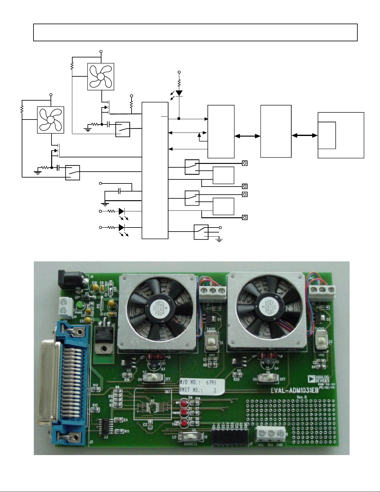
The ADM1030 and ADM1031 function in a very similar
manner. The main difference is that the ADM1031 is dual
channel and the ADM1030 is single channel i.e. the
ADM1031 has a second remote temperature measurement
channel, a second fan speed measurement channel and a
second PWM fan speed control channel.
The ADM1030/31 is an ACPI compliant two/three
channel digital thermometer and under/over temperature
alarm, for use in personal computers. A PWM Fan
Control Output controls the speed of cooling fans. The
speed of these fans may be monitored using the Tach
Inputs. A dedicated Fan Speed Control Loop provides
control even without CPU Intervention.
The device has a programmable INT output to indicate
error conditions. The THERM pin is a failsafe output for
over temperatire conditions.
EVALUATION SYSTEM PACKAGE CONTENTS
The evaluation system contains the following items
1. The ADM1030/31 Evaluation Board
2. Centronics Cable
3. CD containing this application note, datasheet and the
ADM1030/31 evaluation software.
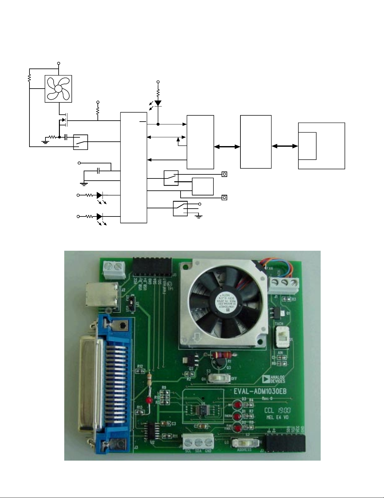
EVALUATION BOARD HARDWARE
The ADM1030/31 evaluation board contains the
following main components which can be identified from
the block diagram, printed circuit board silk screen and
schematic diagram of Figures1, 2 and 3 overleaf.
1. ADM1030 or ADM1031 IC
2. 1 or 2 NPN sensor transistors (depending on whether
ADM1030 or ADM1031 IC is used)
3. LED indicators
4. Interface Buffers
5. Connector for parallel interface.
6. Test Connector for connecting to remote thermal
sensor (J7)
7. Fan (1 or 2 depending on IC).
REV. PrA 10/200 0
Information furnished by Analog Devices is believed to be accurate and
reliable. However, no responsibility is assumed by Analog Devices for its
use, nor for any infringements of patents or other rights of third parties
which may result from its use. No license is granted by implication or
otherwise under any patent or patent rights of Analog Devices.
One T ec hnology Wa y, P.O. Box 9106, Norwood, MA 02062-9106, U.S.A.
Tel: 781/329-4700 Wor ld Wide Web Site: http://www .analog.com
Fax: 781/326-8703 Analog Devices, Inc., 2000
EVAL-ADM1030/31
V
DD
TACH
Preliminary T echnical Data
V
DD
Q2
NDT3055L
D
D
V
D
D
V
D
D
V
V
DD
PWMOUT
S2
D1
RED
THERM
D2
RED
FAN_FAULT
Figure1. ADM1030 Evaluation Board Block Diagram
PRELIMINARY
SDATA
TACH / AIN
ADM10 30
SCLK
V
CC
GND
THERM
ADD
FAN_FAULT
INT
D1+
D1-
D4
RED
INT
BUFFERS
S3
NPN
SENSOR
S5
V
DD
TECHNICAL
DATA
36-WAY
CENTRONICS
CONNECTOR
(J2)*
J5-10
TEST CONNECTOR FOR
CONNECTING O FF BO ARD
REMOTE SENSOR
J5-9
EL
LL
RA
PA
T
R
PO
PC
Figure2. ADM1030 Evaluation Board Picture
–2– REV. PrA
Preliminary T echnical Data
V
DD
TACH
EVAL-ADM1030/31
V
DD
TACH
NDT3055L
Q3
V
DD
Q2
NDT3055L
V
DD
S2
TACH2 / AIN
PWM2OUT
SDATA
INT
ADM10 31
SCLK
PWM1OUT
S1
D
D
V
D
D
V
D
D
V
D1
RED
THERM
D2
RED
FAN_FAULT
PRELIMINARY
TACH1 / AIN
V
CC
GND
THERM
FAN_FAULT
ADD
D1+
D1-
D2+
D2-
D4
RED
INT
36-WAY
BUFF E R S
S3
NPN
SENSOR
S4
NPN
SENSOR
S5
TEST CONNECTOR FOR
BOARD REMOTE SENSOR
TEST CONNECTOR FOR
BOARD REMOTE SENSOR
V
DD
CENTRONICS
CONNECTOR
(J2)*
J7-12
CONNECTING O FF
J7-11
J7-10
CONNECTING O FF
J7-9
EL
LL
RA
PA
T
R
PO
PC
Figure1. ADM1031 Evaluation Board Block Diagram
TECHNICAL
DATA
Figure2. ADM1031 Evaluation Board Picture
–3–REV. PrA

EVAL-ADM1030/31
Preliminary T echnical Data
PRELIMINARY
TECHNICAL
DATA
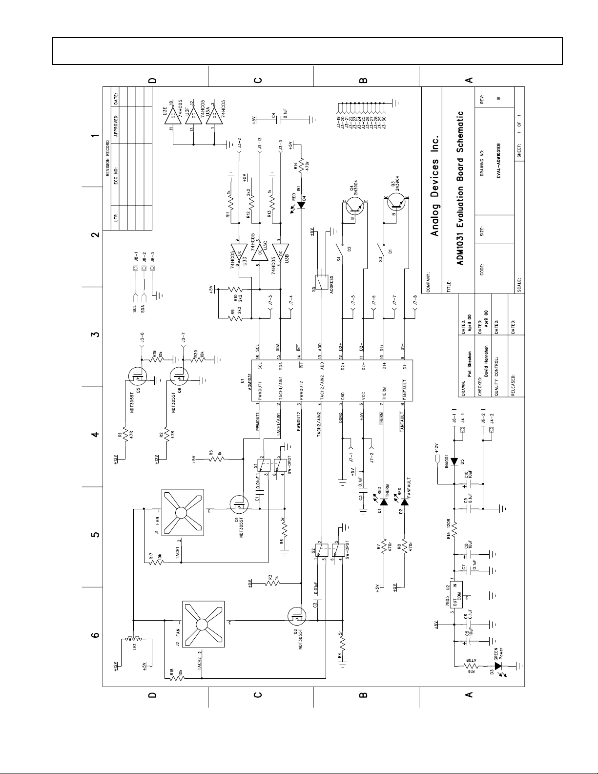
Figure3. ADM1030/31 Evaluation Board Schematic
–4– REV. PrA
Preliminary T echnical Data
EVAL-ADM1030/31
PRELIMINARY
TECHNICAL
DATA
Figure3. ADM1030/31 Evaluation Board Schematic
–5–REV. PrA

EVAL-ADM1030/31
Preliminary T echnical Data
CONNECTORS AND SWITCHES AND INDICATORS
The function of the various connectors, switches and
indicators on the evaluation board are explained below.
CENTRONICS CONNECTOR (J3)
The evaluation board may be connected to the personal
computer via the parallel printer port using the centronics
cable provided.
POWER CONNECTORS (J4 & J6)
Power is supplied to the board via J6 using a 15V Power
Supply mains adaptor. This adaptor is not included in the
evaluation kit. Alternatively power may be supplied to the
board via J4 thus allowing a desktop power supply to be
used.
TEST CONNECTOR (J7)
J7 is provided as a test connector on the ADM1030/31
evaluation board. The remote thermal diode pins, SMBus
and Power pins are all connected to here. This allows the
user easy access to ADM1030/31 signals.
An off board thermal sensor may be connected as the
external sensor via the remote thermal diode pins of the
test connector.
ADDRESS SELECT SWITCH (S5)
The ADM1030/31 has an SMBus Address pin (ADD).
This is a tri-state logic input which sets the lower 2 bits of
the SMBus address.
TABLE1. ADD PIN TRUTH TABLE
ADD Pin A1 A0 SW5
Gnd 0 0 Lo
No Connect 1 0 Center
Vcc 0 1 Hi
THERM LED (D1)
This LED illuminates whenever a measured temperature
exceeds a pre-programmed THERM Limit.
FAN_FAULT LED (D2)
This LED will illuminate whenever a fan fault is detected.
If there is a second fan connected then this should spin up
to full speed.
POWER LED (D3)
This LED illuminates whenever power is supplied to the
board.
PRELIMINARY
FAN CONNECTORS (J1 AND J2)
The fans which are to be controlled by the ADM1030/31
are connected to the board using these connectors.
SMBUS CONNECTOR (J8)
This connector allows the user easy access to the SMBus
signals and may be used if the user wishes to communicate
with the ADM1030/31 in a different way other than using
the Centronics connector.
TACH\AIN SWITCH (S1 AND S2)
This essentially allows the user to switch between a fan
with a Tach Signal and one without. In this case switching
off the Tach signal will automatically switch in the Rsense
circuit which is used to determine the fan speed without
the Tach signal. Details of this method of fan speed
measurement are provided on the datasheet.
REMOTE DIODE SWITCH (S3 AND S4)
This switch allows the user to choose between the onboard remote temperature sensors (Q3 and Q4) and ones
that can be connected to the test connector J7. When the
switch is in the on position the on-board sensors are
selected. When it is in the off position the off-board sensor
is selected.
TECHNICAL
INT LED (D4)
This LED illuminates whenever the ADM1030/31 issues
an interrupt signal (eg. when an out of limit measurement
is made). For more information on the various conditions
DATA
which cause INT to be pulled low please see the datasheet.
–6– REV. PrA

Preliminary T echnical Data
THE SOFTWARE
The software allows the ADM1030/31’s functions to be
controlled from the PC via an easy to use interface
operating under the Windows environment. The
contents of the device’s internal registers can easily be
read or altered through a user-friendly graphics interface,
while the control center window allows the graphing of the
temperature readings.
INSTALLING THE SOFTWARE
To install the software insert the Analog Devices
ADM1030/31 CD-ROM into the CD-ROM Drive. The
CD-ROM should autorun and start installing the software.
If this does not occur then the user should click on the
Start Icon and then on Run Icon and type X:setup.exe as
the file name, where X is the drive letter of the CD-ROM
drive. To finish installing the software follow the
on-screen instructions.
USING THE SOFTWARE
When using the software, first ensure that the evaluation
board is connected to the Parallel Printer Port and that the
power supply is plugged into the board.
To start the Software, select Start-Programs-Analog
Devices- ADM1030/31 Evaluation Software.
When the program is selected the Software Initialisation
Wizard will appear first.
PRELIMINARY
EVAL-ADM1030/31
Once the Communications medium has been selected,
click on “Next” to go to the next screen. When you are
ready for the evaluation software to begin searching for the
device on the chosen medium, click on “Next”.
TECHNICAL
DATA
Click on “Next” to go to the next screen, which will
allow the user to choose between connecting the
evaluation board via the printer port, via the SMBus or via
USB. However the USB option is not available on this
revision of the evaluation board and so should not be
selected.
The software will search for the ADM1030 or ADM1031
and if it finds it the following screen will appear.
Click on “Yes” if this is the ADM1030 or ADM1031 you
wish to use. The next screen should then appear.
–7–REV. PrA

EVAL-ADM1030/31
Preliminary T echnical Data
If the ADM1030 or ADM1031 was not found on the
chosen medium the following screen will appear.
PRELIMINARY
TECHNICAL
In this case check the connections to the board and the
power supply. Then click on “Back” and try again. If this
does not work then try re-booting the PC and re-running
the software.
USING THE SOFTWARE
The index type display which appears on the screen when
the software starts to run has four tabs.
MAIN TAB
The main tab shows the software version and allows the
user to quit the program by clicking on
DATA
Figure4. ADM1030/31 Evaluation Software Main Tab
–8– REV. PrA

Preliminary T echnical Data
EVAL-ADM1030/31
READ/WRITE
This tab displays information about the ADM1030/31’s
internal registers and allows their contents to be read and/
or altered. Each register has a button associated with it.
Clicking on a button will display the contents of the
selected register in the register contents box and the name
of each register bit.
Clicking on a register button causes its contents to be read
once if continuous reading is off. If continuous reading is
on, the register will be updated continuously. Click on the
button to toggle between
and
The type of register selected and its hexadecimal address
is displayed on the right hand side of the screen.
Data may be written to all registers that are Read/Write,
(refer to data sheet for more information). When the Read/
Write tab is first selected, none of the registers have been
written to, and they contain their default values.
Registers may be written to in two ways. Clicking on a bit in
the Read/Write display will toggle its value between 0 and 1.
This is useful where a function is controlled by setting or
clearing individual bits in a register, for example setting or
clearing the Int_Enable bit in the configuration register.
The entire contents of a register may be changed by typing a
Hex or decimal value in the text boxes of the Write display.
The button will change from green to red and the new value
can be written to the register by clicking on the red button.
This is useful where a register contains a numeric value such
as a temperature limit.
PRELIMINARY
TECHNICAL
DATA
Figure5 . ADM1030/31 Read/Write Program Tab
–9–REV. PrA

EVAL-ADM1030/31
Preliminary T echnical Data
VISUAL DISPLAY
The visual display tab allows readings to be displayed
graphically on bargraphs or line graphs.
When the visual display is selected for the first time the
value displayed on the bargraph is the value of local
temperature. To display one of the other values e.g. remote
temperature or fan speed click on the relevant bar graph
button.
EASY SETUP
The line and bargraphs can also be started by clicking on
the
both local and remote temperature. When you click “Easy
Setup” the software prompts the user to ensure that S1 and
S2 are switched to AIN. This is because Esay Setup sets up
the ADM1030/31 for a 2-wire fan. Easy Setup also places
the ADM1030/31 under simple software control.
button. This also sets limits for
FAN SPEED CONTROL
The user may also control fan speed using the PWM duty
cycle select method in the visual display window. This may
be done by adjusting the position of the fan speed control
slider to the required PWM. The duty cycle is displayed as
a percentage at the bottom of the slider. The value written
to the Fan Speed Config Register is displayed on the slider
button.
PRELIMINARY
TECHNICAL
DATA
Figure6. ADM1030/31 Visual Display Program Tab
–10– REV. PrA

Preliminary T echnical Data
EVAL-ADM1030/31
ADM1030/31 MODES OF OPERATION
The ADM1030/31 has four modes of operation. They are
as follows
1. Automatic Fan Speed Control Mode
2. Filtered Automatic Fan Speed Control Mode
3. PWM Duty Cycle Select Mode
4. RPM Feedback Mode
The ADM1030/31 software allows the user to choose which
mode of operation they require. It will then prompt the user
to provide the information required by that particular mode
of operation.
AUTOMATIC FAN SPEED CONTROL MODE.
Click on “Automatic Fan Speed Control” in the “Mode
Select” window in the Control Tab. This causes the
“Automatic Fan Speed Control” window to be displayed.
1. First choose which Control Operation is required, i.e.
which temperature channel controls the fan.
2. Choose the necessary Tmin’s and Trange’s for the
chosen Control Operation.
3. Choose the spin up times for Fan1 and if you are using
the ADM1031 for Fan2 also.
4. Click on “Enable Control”
5. Automatic Fan Speed Control is enabled using the user
defined parameters.
PRELIMINARY
FILTERED AUTOMATIC FAN SPEED CONTROL
MODE.
This mode is almost identical to the Automatic Fan
Speed Control Mode. The main difference is the rate at
which fan speed is ramped up after a temperature
increase. Filtering is implemented by two different
means, selecting the sampling rate of the ADC and
ramping the fan speed to the desired speed (In Automatic Fan Speed Control Mode the fan speed is jumped
immediately to the newly calculated speed). To implement Filtered Automatic Fan Speed Control click on
“Filtered Automatic Control” in the “Mode Select”
window of the Control Tab. This causes the “Filter
Mode” window to be displayed.
1. Choose an “Increment Rate” and an “ADC Sample
Rate”. See the datasheet for more information on these
parameters.
2. The user may also choose to enable or disable “Fan
Spin Up”
3. Finally the user is prompted to choose Automatic
Fan Speed Control Parameters. This should be completed if these Parameters have not already been chosen.
4. Click on “Enable Fan Filter” to implement Filtered
Automatic Fan Speed Control. (Enable Fan1 for the
ADM1030 and Fan1 and Fan2 for the ADM1031)
TECHNICAL
DATA
–11–REV. PrA

EVAL-ADM1030/31
RPM CONTROL MODE
In this method of control the user programs the required RPM
values to the ADM1030/31. Click on the “RPM Feedback
Mode” in the “Mode Select” window of the Control Tab.
1. Enter the required RPM Value in the window.
2. Choose which fan you wish to run at that RPM value.
3. Enter the fan divisor value for that fan.
4. Click on Calculate. The software will calculate Count. This
is the value that has to be written to the ADM1030/31 Tach
High Limit Register to maintain the required speed. See the
datasheet for an explanation of the formulas.
5. Click on “Enable RPM Mode” to place the ADM1030/31 in
RPM Feedback mode.
6. Sometimes after you place a value in the “Enter RPM Mode”
window and click “Calculate” the “Enable RPM Mode” button
does not become active. This is because the Count value is
outside the particular fan’s RPM range. The fan’s RPM range is
determined by the “Fan Divisor Value”.
PWM DUTY CYCLE
In this method the ADM1030/31 is placed under software
control. Fan speed is controlled by programming PWM values
in to the ADM1030/31. Click on “PWM Duty Cycle Select”
in the “Mode Select” window of the Control Tab.
Preliminary T echnical Data
1. Each fan can be programmed with a duty cycle value of
between 0% and 100%.
2. Choose the required PWM value for each fan, the value
chosen must be on the list in the drop down window as the
ADM1030/31 can only be programmed in 6% increments.
3. Click on “Enable PWM Mode”
4. The fan/s should then either spin up or down to the
programmed value.
TEMPERATURE CONTROL
Temperature control allows the user to heat up the remote
thermal diodes on the ADM1030/31 Evaluation Board. First
choose which diode is to be monitored. Then Click on “Enable
Control”. This causes a current to be switched through the two
large heating resistors behind the remote thermal diodes which
in turn causes the remote thermal diodes to heat up. These
resistors can become very hot so care is required. Do not touch
when there is a current flowing through them. Use the slider to
vary the PWM duty cycle applied to the heating resistors.
Adjusting the slider allows limited control of the temperature of
the heating resistors.
PRELIMINARY
TECHNICAL
DATA
–12– REV. PrA

Preliminary T echnical Data
SAVING TO FILE
This window allows the user to save all the ADM1030/31
data to an Microsoft Excel File. The following data is
saved
1.Local Temperature
2.Remote Temperature, channel 1
3.Fan Speed, channel 1, in RPM
4.Channel 1, PWM Duty Cycle
5.Remote Temperature, channel 2
6.Fan Speed, channel 2, in RPM
7.Channel 2, PWM Duty Cycle
To begin saving this data to an Excel file first click on
“Make New Log”. A Windows “Open File” window
should open. Choose a name for the log and then click
“Open”. The software will then begin saving the above
values to the Excel file. The user can also control how often
these values are stored to the Excel file by changing the
value written in the “Delay(Sec)” window. This value
represents the time in seconds between successive saves. To
stop saving to the Excel file the user should click on the
“Logging to file” button.
SAVE/RECALL
This window allows the user to save all the current values in
the device to a .txt file. Click on “Save Register Values”.
This causes the Register Contents Window to be displayed.
Click on “Set File Path” command. The Windows “Open”
Window is then displayed. Choose a filename and Click
“Open”. Then Click on “Save” in the “Register Contents
Window”. This allows a register dump for easy writing of
BIOS Software.
This window also allows the user to program all the
registers with a previously saved set of values. This is
achieved using the “Recall Previous Setup” Command.
Click on “Recall Previous Setup” and choose the .txt
filename of a previous set of register values. Then Click on
“Open”. These previous values are written to the registers.
PRELIMINARY
TECHNICAL
DATA
EVAL-ADM1030/31
–13–REV. PrA

EVAL-ADM1030/31
APPENDIX A. COMPONENT LIST
Capacitors
C1-2, 0.01µF
C3-4, C6, C7, C9 0.1µF
C5, C8, C10 10 µF
Diodes
D1, D2, D4 Red LED
D3 Green LED
D5 IN4001 Diode
Connectors
J1, J2, J8 3-pin Terminal Block
J3 Centronics Connector
J4 2-pin Ter minal Block
J6 DC Barrell Connector
J7 CON\16 Header
Resistors
R1, R2 47 Ω
R3, R5, R11, R13 1 kΩ
R4, R6 5 Ω
R7, R8, R14, R16 47 0Ω
R9, R10, R12 2.2kΩ
R15 Wire Link
R17, R18, R19, R20 10 kΩ
Preliminary T echnical Data
Switches
S1, S2 DPDT Slide Switch
S3, S4 SPDT Slide Switch
S5 SP3T Slide Switch
Semiconductors
Q1, Q2,Q5,Q6 NDT3055L
Q3, Q4 2N3904
U1 ADM1030/31ARQ
U2 74HC05
U3 CD74AC05M
Fans
LK1-A Wire Link
Fan1, Fan2 Panasonic
PRELIMINARY
TECHNICAL
UDQFSDH12F
DATA
–14– REV. PrA
 Loading...