


查询EVAL-ADM1022供应商查询EVAL-ADM1022供应商
Evaluation Board for Microprocessor
a
FEATURES
External Temperature Measurement with Remote Diode
(Two Channels)
On-Chip Temperature Sensor
Interrupt and Overtemperature Outputs
Fault Tolerant Fan Control
Brownout Detection
LDCM Support
2
C Compatible System Management Bus (SMBus)
I
Standby Mode to Minimize Power Consumption
Limit Comparison of all Monitored Values
APPLICATIONS
Network Servers and Personal Computers
Microprocessor-Based Office Equipment
Test Equipment and Measuring Instruments
INTRODUCTION
The ADM1022 Evaluation Board allows the ADM1022
microprocessor system hardware monitor IC to be easily
evaluated using a personal computer. Using both the
evaluation board and its accompanying software, the
ADM1022 can be interfaced to any personal computer
running Windows
computer’s parallel printer port, or via the computer’s
SMBus using the DIMM interface card provided.
The evaluation board allows all the input and output functions of the ADM1022 to be exercised without the need
for external components. The software allows control and
monitoring of the ADM1022’s internal registers.
TM
95 or WindowsTM 98, via the
System Temperature Monitor
EV AL-ADM1022
EVALUATION SYSTEM PACKAGE CONTENTS
The evaluation system package contains the following
items:
* This application note
* ADM1022 evaluation board
* DIMM interface card
* Centronics cable
* DIMM interface ribbon cable
* Evaluation software on floppy disks
EVALUATION BOARD HARDWARE
The ADM1022 evaluation board contains the following
main components, which can be identified from the block
diagram, printed circuit board silk screen and schematic
diagram of figures 1, 2 and 3 overleaf.
* ADM1022 I.C.
* NPN and PNP sensor transistors
* LED indicators for power, resets, interrupt, over-tem-
perature, fan off request, and fan full-on
* Switches for selecting voltage monitoring source, tem-
perature sensors, and for setting device’s SMBus address
* Interface buffers
* Connectors for parallel and SMBus interface
* Test connector
* 3.3V supply regulation circuit
THE ADM1022
The following gives a brief description of the ADM1022.
More detailed device information can be found in the
datasheet for the device. The ADM1022 is a hardware
temperature monitor for personal computers and other
microprocessor systems which features a three-channel
digital thermometer and over-temperature alarm. It can
also control the speed of a cooling fan.
The device can measure local temperature using an onchip diode connected transistor, or can use low cost, small
signal transistors such as the 2N3904 or 2N3906 to measure the temperatures of 2 external microprocessors. The
measurement technique implemented, cancels the absolute
value of the transistor’s base emitter voltage, so that no
calibration is required.
REV. B
Information furnished by Analog Devices is believed to be accurate and
reliable. However, no responsibility is assumed by Analog Devices for its
use, nor for any infringements of patents or other rights of third parties
which may result from its use. No license is granted by implication or
otherwise under any patent or patent rights of Analog Devices.
REQUIREMENTS
* PC running Windows 95 or Windows 98
* 15Vdc 300mA regulated power supply
One T ec hnology Way , P.O. Box 9106, Norwood, MA 02062-9106, U.S.A.
Tel: 781/329-4700 Wor ld Wide Web Site: http://www .analog.com
Fax: 781/326-8703 Analog Devices, Inc., 1998
EVAL-ADM1022
V
DD
PNP
SENSOR
NPN
SENSOR
EXTERNAL
SENSOR
D3
FAN_OFF
TEST
CONNECTOR
J1
D2+
D2-
D1+
D1-
SCLK
SDA
GND
V
MON
V
DD
ADDSW2
FAN_OFF
MR
ADM1022
SDATA
D2+
D2-
SCLK
D1+
D1-
FAN_SPD
RST1 RST2
D2
AUX_RST RESET
VDDV
INT
V
V
DD
D6
RED
INTERRUPT
10-WAY
CONNECTOR
FOR SMBUS
(J4)*
BUFFERS
36-WAY
CENTRONICS
CONNECTOR
V
D4
GREEN
POWER
DD
FAN
DD
D1
DD
(J2)*
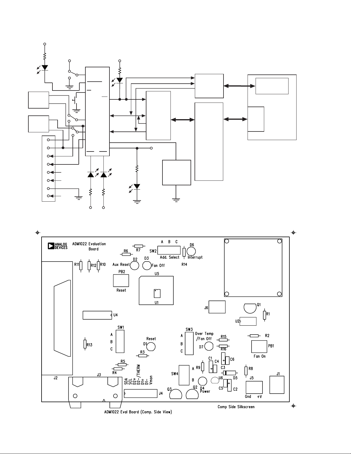
Figure 1. ADM1022 Evaluation Board Block Diagram
DIMM INTERFACE
CARD
PC
PORT
PARALLEL
USE EITHER J2 OR J4 BUT NOT BOTH
Figure 2. ADM1022 Evaluation Board SilkScreen
–2– REV. B
EVAL-ADM1022
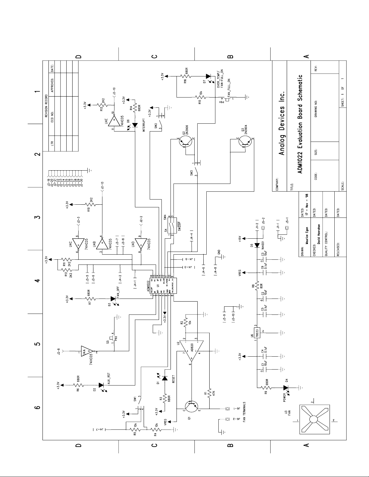
DM1022.sch-1 - Tue Dec 08 11:59:10 1998
–3–REV. B

EVAL-ADM1022
CONNECTORS, SWITCHES AND INDICATORS
The function of the various connectors, switches and indicators on the evaluation board is explained below.
TEST CONNECTOR J4
Test connector J4 allows the serial data and clock lines of
the ADM1022 and the THERM line to be monitored.
The connector also allows access to the V
and GPI
MON
lines.
Alternative external diode sensors may be connected be-
tween the D1 and D2 pairs of inputs.
CENTRONICS INTERFACE CONNECTOR J2
If the personal computer being used with the evaluation
board does not have a System Management Bus on the
motherboard, connection between the evaluation board
should be made via a parallel printer port, using the cable
provided. The connections to J2 are as follows:
TABLE 1. J2 CONNECTIONS
J2 Pin ADM1022 Function Parallel Port Function
2 Serial Clock (SCLK) DB0
3 Serial Data In (SDA) DB1
8 Manual Reset (MR) DB6
10 Interrupt (INT) ACK
13 Serial Data Out (SDA) SLCT
19-30 Gnd Gnd
SMBUS INTERFACE CONNECTOR J3
The SMBus interface connector J3 allows the evaluation
board to be connected directly to the SMBus of a personal
computer, using the DIMM interface card provided. To
make this connection, it may be necessary to remove one
of the DIMM memory modules on the PC motherboard,
if all DIMM sockets are occupied. This will affect the
BIOS setup and Windows 95, and should only be attempted by a competent user.
REMOTE SENSOR SELECT SWITCHES SW4, SW3
Two remote sensors are provided on the evaluation board;
a 2N3904 and a 2N3906 transistor. Alternative remote
sensors may be connected between the D1 and D2 terminals on the test connector J4.
TABLE 2. REMOTE SENSOR SELECT; SW4, SW3
SW4 Position SW3 Position Sensor Selected
1 2
O FF OF F C D1/D2(connector J4)
ON - A 2N3906 (D2)
- ON - 2N3904 (D1)
ON ON A D1 and D2 selected
SERIAL BUS ADDRESS SELECT (SW2)
SW2 is used to set the two LSB’s of the ADM1022’s serial bus address, A1 and A0. The ADD pin is tri-state and
can be grounded, left unconnected or tied to V
. This
CC
means a total of three addresses are possible. It should be
noted that the ADD pin is only read at power-up. If SW2
is changed while the ADM1022 is on, the change of address will not be effective until the device has been powered off, and on again.
As the serial bus address is 7 bits, when storing it as an 8bit word it must be left or right justified, with either the
MSB or the LSB of the 8-bit word as zero. The
ADM1022 evaluation software stores the 7-bit serial bus
address as left-justified and makes the LSB zero. Table 3
shows the three possible addresses for the ADM1022.
TABLE 3. ADM1022 DEVICE ADDRESSES
SW2 Position A1 A0 Device Address
A (Gnd) 1 0 5C (Hex)
B (NC) 0 0 58 (Hex)
C (Vcc) 0 1 5A (Hex)
V
SELECT SWITCH, SW1
MON
This switch allows the V
pin to monitor either the on-
MON
board 3.3V supply, an external 3.3V supply through connector J4, or a larger external supply voltage through J4,
applied across voltage divider network R4, R5. Table 4
shows the relevant switch positions.
TABLE 4. V
SW1 Position Voltage Source (V
SELECT SWITCH, SW1
MON
mon
)
A External 5V on J4
B External 3.3V on J4
C On-board 3.3V
–4– REV. B

EVAL-ADM1022
THERMTHERM
D2/
THERM SELECT SWITCH, SW3
THERMTHERM
This switch selects either the on-board 2N3906 temperature sensing transistor, or an off-board transistor connected to the D2 inputs of test connector J4.
If a second thermal diode is unwanted, the THERM function on the ADM1022 may be used. If THERM is selected, LED D7 will indicate any over-temperature
measurements.
TABLE 5. D2/
SW3 Position Selected Function
A Remote D2 on J4
B Over-temperature and fan full-on
C On-board 2N3906
RESET SWITCH, PB2
When this pushbutton switch is pressed, it will assert
RST2 low. RST2 will remain low for t
leased. This can be used to reset some external circuitry.
FAN FULL-ON SWITCH, PB1
When this pushbutton switch is pressed, THERM is
pulled low. This causes the FAN_SPD output to go fullscale (2.5V), and the fan goes to full speed. The FAN
FULL-ON LED, D7 also lights up.
THERMTHERM
THERM SWITCH, SW3
THERMTHERM
status on LED D7
after PB2 is re-
RP
INSTALLING THE SOFTWARE
To install the software, insert the first disk of the program
software supplied into drive A, click on the Start icon,
click on Run, and then type A:setup.exe as the file name.
If the 3.5-inch floppy disk drive is not drive “A”, type
“X” instead of “A”, where “X” is the drive letter of the
3.5-inch floppy disk drive.
USING THE SOFTWARE
When using the software, first ensure that the evaluation
board is connected to the Parallel printer port, or to the
PC’s SMBus using the DIMM interface card.
To start the software, select Start- Programs- ADM1022
Evaluation Software.
When the program is started, the Software Initialisation
Wizard screen will appear.
TABLE 6. INDICATOR LED’s
LED WHEN LIT
D1 When RST2 asserts on power-up or PB2
is pressed.
D2 When RST1 asserts on power-up.
D3 When FAN_OFF output is asserted.
D4 When board is powered.
D6 When an interrupt condition occurs.
D7 When an over-temperature condition oc-
curs (THERM asserted), or when the fan
is set to full speed by pressing PB1.
THE SOFTWARE
The software allows the ADM1022’s functions to be controlled from the PC via an easy to use interface, operating
under the Windows environment. The contents of the
device’s internal registers can easily be read or altered
through a user-friendly graphical interface, while the Visual Display window allows temperature readings to be
graphed.
–5–REV. B

EVAL-ADM1022
Click on “Next” to go on to the next screen, which allows
the user to select between connection of the evaluation
board via the printer port or to the SMBus using the
DIMM interface card.
Once the communications medium has been selected,
click on “Next” to go to the next screen. When you are
ready for the software to begin searching for the evaluation
board on either the parallel port or the SMBus, click
“Next”.
The software will search for the ADM1022, and when it is
found, the following screen will appear. The device address found will depend on the setting of Address Select
switch, SW2.
If “Yes” is selected, then the following message appears.
If “No” is chosen, then the software will search for another ADM1022 device at a different address. This feature
is useful if multiple ADM1022’s exist on the same SMBus
and you need access to one of the devices at a different
address.
–6– REV. B

If the ADM1022 is not found on the printer port, the following message will appear:-
EVAL-ADM1022
In this case, check the connections to the evaluation
board, click on “< Back” and try again. If this does not
work, then try re-booting the PC and re-running the software.
When the software has successfully found the ADM1022,
click on “Finish”. An index-card type display with three
tabs will appear.
The main tab is the splash screen. It shows the software
version and clicking on the “About” button, pops-up the
About dialog box showing more information on the software.
On-line help may be accessed at any time during the
software’s use by pressing F1 on the keyboard.
It is also possible to quit the program by clicking on the
close button
If the ADM1022 is not found on the SMBus, the following message will appear:-
–7–REV. B

EVAL-ADM1022
Figure 3. Main Program Tab
READ/WRITE
This tab displays information about the ADM1022’s internal registers. It allows their contents to be read and/or
altered. Each register has a label associated with it printed
on the tab. Moving the mouse pointer over the label
changes the register label colour to light green. When the
register label is clicked, it becomes a highlighted yellow.
Now this register will become the default on-screen register and the register label will turn dark green to indicate
this.
The contents of the selected register will be displayed in
the register contents box, along with the name of each
individual register bit. The register contents are also displayed in hexadecimal and decimal format.
Clicking on a register label will cause its contents to be
read once if continuous reading is off. If continuous reading is on, the register contents will be displayed continuously; allowing any register bit changes to be viewed
immediately.
When a register label is clicked, it performs a single read
of that register from the ADM1022. Therefore, continuous reading will be off:-
If however, the user wishes to continuously monitor the
selected register, then this can be done by toggling the
continuous reading button to its on-state.
When a register label has been clicked, the Read/Write
portion of the form reflects each individual bit of the selected register. Thus, any bit of the register may be modified or monitored in this box.
–8– REV. B

EVAL-ADM1022
Alternatively, the entire contents of a register may be
changed by typing a Hex or Decimal value in the “Write”
text box. When the contents of the text box is altered, the
button alongside will change from green to red, signifying
a newly entered value. Clicking on the red button will
write the updated value to the selected register.
This feature is useful where a register contains a numeric
value, such as a temperature limit.
Another useful portion of the form provides info about the
selected register; the address of the register, and the previous values read and written to/from the register.
VISUAL DISPLAY
The Visual Display tab allows all three temperature measurement channels to be monitored and graphed.
EASY SETUP
At the bottom of the Visual Display Tab is the “Easy
Setup” button:-
If the ADM1022 has been configured for only one remote
thermal diode, then pressing “Easy Setup” will graph the
Internal Temperature and the Remote Diode temperature.
If the ADM1022 has been configured for both remote
thermal diode channels, then pressing the “Easy Setup”
button will graph the Internal Temperature and the two
Remote Diode temperature channels.
Figure 4. Read/Write Program Tab
–9–REV. B

EVAL-ADM1022
BARGRAPH
On the left-most position of the Visual Display tab is the
bargraph control/indicator. This 3D-type indicator gives a
visual indication of the selected temperature channel. The
bargraph also has 2 moveable controls; these control the
upper and lower interrupt limits which may be set for each
temperature channel. Once the temperature moves outside
these limits, an interrupt will be generated if the interrupt
source is unmasked in the Interrupt Mask Register (please
refer to the ADM1022 datasheet for more detailed interrupt information).
Each temperature channel’s limits may be adjusted independently of the next channel, by selecting the channel
from the bargraph panel on the Visual Display tab. The
channel may be selected by clicking on it, and will turn
green to indicate its selection.
The temperature value is displayed below the bargraph,
allowing absolute readings to be monitored. The bargraph
gives a useful indication of whether temperature is rising
or falling, and the rate at which it is doing so.
If the temperature goes outside the programmed limits, an
error is generated for that channel, and the bargraph panel
will give a visual indication of this.
As shown above, when the temperature goes beyond a
programmed temperature limit (86°C in this case), an
interrupt is generated and the LED lights up for that
channel. External 1 is the channel being displayed, since
the label is green. The absolute temperature on that channel is 112°C, as shown at the base of the temperature
bargraph.
FAN SPEED CONTROL
The ADM1022 can control the speed of a fan connected
to it. This tab contains a slider control to manually adjust
the default fan speed.
–10– REV. B

GRAPHING
On the right-most of the Visual Display tab is a line
graph. Once the “Easy Setup” button is clicked, graphing
begins. Each temperature channel is plotted against time.
The graph contains a colour legend to associate each
coloured line with each temperature channel.
While the graph is displayed on the screen, it is possible
to zoom in or out by moving the arrows on the temperature and time axes. Moving the lower arrow up the temperature axis, increases the minimum temperature shown
on the graph, while moving the upper arrow down decreases the maximum temperature displayed. This effectively allows zooming in on a narrower temperature range.
Similarly, moving the left arrow to the right on the time
axis and/or the right arrow to the left, displays a narrower
band of time on this axis.
The graph can be cleared at any time by pressing the
“Easy Setup” button again. Note that doing so will cause
all the registers to be re-initialised to their default values.
EVAL-ADM1022
While the display is graphing, the user can click on the
Read/Write tab, and make any adjustments, without having
to stop the graphing. This feature can be useful for enabling or disabling interrupts, or other functions, whilst
still measuring temperature.
Figure 5. Visual Display tab
–11–REV. B

EVAL-ADM1022
Figure 6. Normal Graph
Fig 7. Zoomed In Graph
–12– REV. B

EVAL-ADM1022
APPENDIX A. ADM1022 REGISTERS
More detailed information on each of the registers may be found in the ADM1022 datasheet.
TABLE7. LIST OF ADM1022 REGISTERS
Register Name Address A7 - A0 in hex Comments
Value Registers 0x13 – 0x3A See Table 8
Company ID 0x3E This location will contain the company identification
number. This register is read only.
Revision 0x3F This location will contain the revision number of the
part in the lower four bits of the register [3:0]. The
upper four bits reflect the ADM1022 Version Number
[7:4]. The first version is 1100. The next version of
ADM1022 would be 1101, etc. For instance, if the
stepping were A0 and this part is a ADM1022, then
this register would read 1100 0000. This register is
read only.
Configuration Register 0x40 Power on value = 0010 0101
Interrupt Status Register 0x41 Power on value = 0000 0000
Interrupt Mask Register 0x43 Power on value = 0000 0000
Interrupt Status Register Mirror 0x4C Power on value = 0000 0000
TABLE 8. REGISTERS 0X13- 0X3A VALUE REGISTERS
Address Read/Write Description
0x13 Read/Write Programmable Local Temp Sensor Automatic Trip Point - default 70 degrees C.
This register can only be written to if the write once bit in the configuration register
(0x40, bit 3) has not been set.
0x14 Read/Write Programmable Remote Thermal Diode Automatic Trip Point - default 100 degrees C.
This register can only be written to if the write once bit in the configuration register
(0x40, bit 3) has not been set.
0x15 Read/Write Test register for manufacturer’s use only. Do not write to this register
0x17 Read Only Default Local Temp Sensor Automatic Trip Point - default 70 degrees C
Cannot be changed. Disabled when bit 3 of Config. register is set
0x18 Read Only Default Remote Thermal Diode Automatic Trip Point - default 100 degrees C
Cannot be changed. Disabled when bit 3 of Config register is set
0x19 Read/Write Analog Output, FAN_SPD (defaults to 0x00h)
0x20 Read Only External Temperature Value Diode 2
0x26 Read Only External Temperature Value Diode 1
0x27 Read Only Internal Temperature
0x2B Read/Write External Temperature Diode 2 High Limit
0x2C Read/Write External Temperature Diode 2 Low Limit
0x37 Read/Write External Temperature Diode 1 High Limit
0x38 Read/Write External Temperature Diode 1 Low Limit
0x39 Read/Write Internal Temperature High Limit
0x3A Read/Write Internal Temperature Low Limit
–13–REV. B

EVAL-ADM1022
APPENDIX B. COMPONENT LIST
Capacitors
C1,C2,C3 10µF tantalum
C4,C5,C6 0.1µF
Resistors
R1 47k
R2,R4,R5,R15 10k
R3,R6,R7,R9,R14,R16 680R
R8 80R
R10,R11,R12,R13 2k2
Semiconductors
Q1,Q3 2N3904
Q2 2N3906
D1,D2,D4 Green LED
D3,D6,D7 Red LED
D5 1N4001
U1 ADM1022
U2 AD820
U4 74HC05
U6 78L033
Connectors
J1 Power socket
J2 36-way Centronics
J3 10-way R.A. IDC socket
J4 2mm 8-way test socket
J5,J6 Terminal post
Switches
SW1,SW2,SW3 3-way slide switch
SW4 DIL switch
PB1,PB2 pushbutton switch
Miscellaneous
U3 12V dc fan
–14– REV. B
 Loading...