


 Loading...
UNCRATING/INSTALLATION INSTRUCTIONS
AMSCO® RELIANCE® 130/130L
Cart and Utensil Washer/Disinfector
(09/17/01) |
P-122997-959 |
Rev. 4 |
|

LIMITATIONS OF LIABILITY AND INDEMNITY
IN NO CASE, WHETHER AS A RESULT OF A BREACH OF CONTRACT, BREACH OF WARRANTY, OR TORT (INCLUDING STERIS’S OR CUSTOMER’S WILLFUL ACTS, NEGLIGENCE, OR STRICT LIABILITY) SHALL STERIS OR CUSTOMER BE LIABLE TO THE OTHER FOR ANY
CONSEQUENTIAL OR INCIDENTAL DAMAGES INCURRED BY THE OTHER, INCLUDING, BUT
NOT LIMITED TO, LOSS OF REVENUE, PROFITS, OR GOODWILL. HOWEVER, NOTHING CONTAINED IN THIS MANUAL IS INTENDED TO RELIEVE EITHER STERIS OR CUSTOMER
FROM CLAIMS, LIABILITY, DAMAGES, OR EXPENSES RESULTING FROM BODILY INJURY,
INCLUDING DEATH, OR FROM PROPERTY DAMAGE INCURRED DUE TO THE WILLFUL ACTS, NEGLIGENCE, OR STRICT LIABILITY OF THAT PARTY.
STERIS AGREES TO DEFEND, INDEMNIFY, AND HOLD CUSTOMER HARMLESS FROM ANY AND ALL CLAIMS, LIABILITY, DAMAGES, OR EXPENSES DUE TO PERSONAL INJURIES,
INCLUDING DEATH, TO EMPLOYEES OF STERIS AND CUSTOMER AND TO THIRD PARTIES
AND FOR PROPERTY DAMAGE TO THE EXTENT CAUSED BY THE WILLFUL ACTS, NEGLIGENCE, OR STRICT LIABILITY OF STERIS . CUSTOMER AGREES TO DEFEND, INDEMNIFY,
AND HOLD STERIS HARMLESS FROM ANY AND ALL CLAIMS, LIABILITY, DAMAGES, OR
EXPENSES DUE TO PERSONAL INJURIES, INCLUDING DEATH, TO EMPLOYEES OF CUSTOMER AND STERIS AND TO THIRD PARTIES AND FOR PROPERTY DAMAGE TO THE
EXTENT CAUSED BY THE WILLFUL ACTS, NEGLIGENCE, OR STRICT LIABILITY OF CUS-
TOMER.
WARNING - COPYING PROHIBITED
This manual is protected by Federal Copyright Law, which provides for damages of up to $20,000, as well as criminal fines and imprisonment, for unauthorized copying.

A WORD FROM STERIS CORPORATION
Follow each step of the Uncrating/Installation instructions in the order presented. Open the carton carefully to avoid damage to the equipment inside. If you find any indication of damage to the equipment (no matter how slight), show it to your supervisor.
To properly install this unit, you will need the Equipment Drawings (previously furnished), showing all utility service and space requirements. If drawings cannot be located, replacement copies may be obtained by writing, faxing or telephoning STERIS giving the serial and model numbers of your equipment.
If your Amsco® Reliance® 130L Cart and Utensil Washer/Disinfector (pit-mounted) is equipped with an Amsco® Reliance® 130 Automated Transport System: When indicated in this manual, refer to 130 ATS Uncrating/Installation Manual (P-920010-101) for specific instructions.
Once installed, equipment operation should be tested by a qualified service technician prior to your usage of the equipment.
If STERIS supervision is desired, for installing and starting up this equipment, contact your local STERIS representative.
Indications For Use
Advisory
©2001 - STERIS Corporation All rights reserved.
The Amsco® Reliance® 130/130L Cart and Utensil Washer/ Disinfector is a high capacity mechanical washer/disinfector intended for use in the efficient washing, low-level disinfection and drying of utensils, carts and other miscellaneous reusable items used in the care of patients.
The Amsco Reliance 130/130L Cart and Utensil Washer/Disinfector is equipped with a fully programmable Amsco Eagle® 3000 Stage IV microprocessor control system.
This washer is specifically designed to only process goods as outlined in this manual. If there is any doubt about a specific material or product, contact the manufacturer of the product for the recommended washing techniques.
A listing of safety precautions to be observed when uncrating, installing and testing this equipment can be found in Section 1 of these instructions. Do not begin uncrating or installation of this equipment until you have become familiar with this information.
Any alteration of the washer not authorized or performed by STERIS Engineering Service which could affect its operation will void the warranty, could adversely affect washing efficacy, could violate federal, state and local regulations, and could jeopardize your insurance coverage.
IMPORTANT: Be sure to check local occupational health and safety regulations, as well as electric and plumbing codes, for any special requirements that may pertain to installation of this unit.
Printed in Canada
i
Table of Contents |
Uncrating/Installation Instructions |
P-122997-959 |

A thorough preventive maintenance program is essential to safe Service Information and proper equipment operation. You are encouraged to contact your STERIS representative concerning extended service maintenance agreements to give your washer planned maintenance, assuring equipment performance according to factory specifications. A global network of skilled service specialists can provide periodic inspections and adjustments to assure low-cost peak performance. STERIS representatives can provide information
regarding Annual Maintenance Agreements.
STERIS carries a complete line of accessories for use in this equipment. A STERIS representative will gladly review these with you.
Sales and Service |
|
|
|
Information: |
Technical Assistance: |
||
STERIS Corporation |
STERIS Engineering Services |
||
5960 Heisley Road |
2424 West 23rd Street |
||
Mentor, Ohio 44060 |
Erie, PA 16506 |
||
Tel.: |
440 354 2600 |
Tel.: |
814 452 3100 |
Fax: |
440 639 8199 |
Fax: |
814 870 8400 |
Manufacturing Plant: |
Authorized EU Representative: |
|
STERIS Canada Corporation |
STERIS Limited |
|
415, rue des Alleghanys |
STERIS House |
|
Beauport (Quebec) |
Jays Close |
|
Canada G1C 4N4 |
Viables |
|
Tel.: |
418 664 1549 |
Basingstoke |
Fax: |
418 664 0188 |
Hampshire RG22 4ZX |
|
|
United Kingdom |
|
|
Tel.: 44 1256 840400 |
|
|
Fax: 44 1256 866502 |
STERIS Offices Worldwide: |
|
|
Canada |
800 661 3937 |
|
Germany |
49 2233 6999 400 |
|
Hong Kong |
852 2 563 3623 |
|
Italy |
|
39 0141 590429 |
Japan |
81 78 252 1901 |
|
Korea |
|
82 2 554 1661 |
Latin America |
305 442 8202 |
|
Singapore |
65 841 7677 |
|
Spain |
|
3491 658 5920 |
United Kingdom |
44 1256 840400 |
|
Web Site: www.steris.com
ii
P-122997-959 |
Uncrating/Installation Instructions |
Table of Contents |

 This Amsco Reliance 130/130L Cart and Utensil Washer/Disinfector Certification complies with the following standards:
Governing directive for the affixing of the CE mark:
Medical Devices Directive (93/42/EEC), Annex II.
Standards applied to demonstrate conformity to the directives:
EN / IEC -61010-1 (1993) A1 (1992) A2 (1995), EN 50082-1, EN50011, CISPR 11 (1991), EN 50082-2, EN 61000-4-2, EN 61000-4- 3/ ENV 50140, ENV 50204 (1996), EN 61000-4-4 (1995), EN 61000- 4-6 (1996) / ENV 50141 (1993), EN-294 (1992), EN-349 (1993), ISO3746 (1979), EN-418 (1992), EN 292-1 (1991), EN 292-2 (1991), EN 457 (1992).
iii
Table of Contents |
Uncrating/Installation Instructions |
P-122997-959 |
This page intentionally left blank.
iv
P-122997-959 |
Uncrating/Installation Instructions |
Table of Contents |

TABLE OF CONTENTS
SECTION |
TITLE |
PAGE |
|
|
|
1 |
LITING OF WARNINGS, CAUTIONS AND |
|
|
SYMBOLS .................................................................... |
1-1 |
|
Definition of Symbols ..................................................... |
1-3 |
2 |
SITE PREPARATION ................................................... |
2-1 |
|
Technical Specifications ................................................ |
2-1 |
|
Amperage and Power Consumption ........................ |
2-1 |
|
Noise Level ............................................................. |
2-1 |
|
Permissible Environmental Conditions .................... |
2-1 |
|
Before Installing Equipment ........................................... |
2-2 |
3 |
UNCRATING/INSTALLATION INSTRUCTIONS .......... |
3-1 |
|
Open Crates .................................................................. |
3-1 |
|
Assembled Unit ....................................................... |
3-1 |
|
Control Panel Installation......................................... |
3-3 |
|
Disassembled Unit .................................................. |
3-7 |
|
Disassembled Unit Assembly ........................................ |
3-9 |
|
Crate A ................................................................... |
3-9 |
|
Sump....................................................................... |
3-9 |
|
Non-Service Side Walls .......................................... |
3-11 |
|
Service Side Walls .................................................. |
3-13 |
|
Control Configuration .............................................. |
3-13 |
|
Temporary Roof Supports ....................................... |
3-15 |
|
Roof ........................................................................ |
3-17 |
|
Crate B ................................................................... |
3-19 |
|
Roof End ................................................................. |
3-21 |
|
Door Rail Holders .................................................... |
3-23 |
|
Roof Components ................................................... |
3-25 |
|
Emergency Guard Rails .......................................... |
3-27 |
|
Spray Headers ........................................................ |
3-29 |
|
External Cabinet Corners ........................................ |
3-31 |
|
Door Frames ........................................................... |
3-33 |
|
Roller Stoppers ....................................................... |
3-35 |
|
Door Panels ............................................................ |
3-37 |
|
Ventilation Duct ....................................................... |
3-39 |
|
Pulley Guards.......................................................... |
3-41 |
|
Traveler Cable ......................................................... |
3-43 |
|
Traveler Safety Cable.............................................. |
3-45 |
|
Crate C ................................................................... |
3-47 |
|
Mobile Mechanical Core ................................................ |
3-47 |
|
Move and Remove Skid .......................................... |
3-47 |
|
Mechanical Core ..................................................... |
3-51 |
v
Table of Contents |
Uncrating/Installation Instructions |
P-122997-959 |

TABLE OF CONTENTS (CONT'D)
SECTION |
TITLE |
PAGE |
|
Leveling Legs .......................................................... |
3-53 |
|
Crate D ................................................................... |
3-55 |
|
Drying System Assembly ........................................ |
3-55 |
|
Pneumatic Connections .......................................... |
3-57 |
|
Door Links ............................................................... |
3-61 |
|
Electrical Connections ............................................. |
3-63 |
|
Connect Utilities ............................................................ |
3-67 |
|
Service Panels and Transition Plates ............................ |
3-69 |
|
Ramp Option ................................................................. |
3-71 |
|
Service Access Panels .................................................. |
3-73 |
|
Cleanup ......................................................................... |
3-75 |
4 |
INSTALLATION CHECKLIST ...................................... |
4-1 |
5 |
START-UP TEST .......................................................... |
5-1 |
|
How to Enter Factory Set-Up Mode ............................... |
5-2 |
|
How to Verify Indicator Lights .................................. |
5-4 |
|
How to Verify Door Configuration ............................ |
5-5 |
|
How to Enter Service Mode ........................................... |
5-6 |
|
How to Activate Digital Outputs ............................... |
5-7 |
|
How to Verify Suction Pump Rotation ..................... |
5-11 |
|
How to Verify Exhaust Fan Rotation (Option) .......... |
5-12 |
|
Air /Oil Tanks .......................................................... |
5-13 |
|
Calibration ..................................................................... |
5-15 |
|
How to Calibrate Chemical Injection Rate ............... |
5-15 |
|
How to Perform RTD Calibration ............................. |
5-18 |
|
How to Perform Hot Water Flowmeter Calibration. .. |
5-20 |
|
Miscellaneous Verifications in Automatic Mode ............. |
5-21 |
|
Safety Features. ...................................................... |
5-21 |
|
Automatic Floor Tilt ................................................. |
5-25 |
|
Manual Damper Adjustment .................................... |
5-25 |
|
Automatic Damper Adjustment ................................ |
5-26 |
|
Clean Steam Supply Valve ...................................... |
5-26 |
|
Operational Test with 130L Load/Unload Modules ........ |
5-28 |
vi
P-122997-959 |
Uncrating/Installation Instructions |
Table of Contents |

LIST OF ILLUSTRATIONS AND TABLES
FIGURE |
TITLE |
PAGE |
|
|
|
|
|
2-1. |
Utility Service Connections ............................................................................................................... |
2-2 |
|
3-1. |
Crates............................................................................................................................................... |
|
3-2 |
3-2. |
Amsco® Reliance® |
130/130L Cart and Utensil Washer/Disinfector, Center of Gravity ...................... |
3-4 |
3-3. Amsco® Reliance® |
130/130L Cart and Utensil Washer/Disinfector, Reference View Point |
|
|
|
for all Installation Locations .............................................................................................................. |
3-6 |
|
3-4. |
Pit Mounted Unit ............................................................................................................................... |
|
3-8 |
3-5. |
Non-Service Side Walls ................................................................................................................... |
3-10 |
|
3-6. |
Service Side Walls .......................................................................................................................... |
3-12 |
|
3-7. |
Temporary Roof Supports ............................................................................................................... |
3-14 |
|
3-8. |
Roof................................................................................................................................................. |
|
3-16 |
3-9. |
Roof End ......................................................................................................................................... |
|
3-20 |
3-10. |
Door Rail Holders ............................................................................................................................ |
|
3-22 |
3-11. |
Roof Components |
........................................................................................................................... |
3-24 |
3-12. |
Crate D: Inside Chamber Components ............................................................................................ |
3-26 |
|
3-12A.Spray Headers ................................................................................................................................ |
|
3-28 |
|
3-13. |
External Cabinet Corners ................................................................................................................ |
3-30 |
|
3-14. |
Door Frames ................................................................................................................................... |
|
3-32 |
3-15. |
Roller Stoppers ................................................................................................................................ |
|
3-34 |
3-16. |
Door Panels .................................................................................................................................... |
|
3-36 |
3-17. |
Ventilation Duct ............................................................................................................................... |
|
3-38 |
3-18. |
Pulley Guards .................................................................................................................................. |
|
3-40 |
3-19. |
Traveler Cable ................................................................................................................................. |
|
3-42 |
3-20. |
Traveler Safety Cable ...................................................................................................................... |
3-44 |
|
3-21 |
Slide Mechanical Core ..................................................................................................................... |
3-46 |
|
3-22. |
Mobile Mechanical Core - Center of Gravity .................................................................................... |
3-48 |
|
3-23. |
Mechanical Core Piping ................................................................................................................... |
3-49 |
|
3-24. |
Leveling Legs .................................................................................................................................. |
|
3-52 |
3-25. |
Drying System ................................................................................................................................. |
|
3-54 |
3-26. |
Floor Tilt Pneumatic Connections .................................................................................................... |
3-56 |
|
3-27. |
Top of Washer, Pneumatic Connections ......................................................................................... |
3-58 |
|
3-28. |
Door Links ....................................................................................................................................... |
|
3-60 |
vii
Table of Contents |
Uncrating/Installation Instructions |
P-122997-959 |

LIST ILLUSTRATIONS AND TABLES (CONT'D)
FIGURE |
TITLE |
PAGE |
||
|
|
|
|
|
3-29. |
Electrical Connections ..................................................................................................................... |
|
3-62 |
|
3-30. |
Supplies Connections ...................................................................................................................... |
|
3-66 |
|
3-31. Service Panels and Transition Plates .............................................................................................. |
|
3-68 |
||
3-32. |
Ramp Option ................................................................................................................................... |
|
3-70 |
|
3-33. |
Service Access Panels (1 of 2)........................................................................................................ |
|
3-72 |
|
3-34. |
Service Access Panels (2 of 2)........................................................................................................ |
|
3-74 |
|
5-1. Control Panel and Printer ................................................................................................................. |
|
5-2 |
||
5-2. |
|
Air/Oil Tanks .................................................................................................................................... |
|
5-14 |
5-3. |
|
Chemical Injection Ports .................................................................................................................. |
|
5-16 |
5-4. |
Emergency Exit Safety Doors.......................................................................................................... |
|
5-22 |
|
5-5. |
|
Exhaust Damper Adjustment ........................................................................................................... |
|
5-24 |
LIST OF TABLES
5-1. |
I/O Board Outputs Tests ................................................................................................................... |
5-8 |
5-2. |
I/O Board Inputs Tests ..................................................................................................................... |
5-9 |
5-3 |
Control Board Analog Inputs Test ..................................................................................................... |
5-9 |
5-4 |
Interlock Features ............................................................................................................................ |
5-10 |
viii
P-122997-959 |
Uncrating/Installation Instructions |
Table of Contents |
LISTING OF WARNINGS, CAUTIONS AND |
1 |
SYMBOLS |
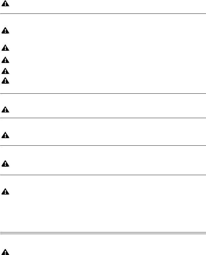
The following is a listing of the safety precautions which must be observed when uncrating, installing and operating this equipment. WARNINGS indicate the potential for danger to personnel and CAUTIONS indicate the potential for damage to equipment. These precautions are repeated, where applicable, throughout the instructions.
WARNING - PERSONAL INJURY AND/OR EQUIPMENT DAMAGE HAZARD:
When moving the unit, use a forklift.
Only fully qualified service personnel should assemble and/or make adjustments to this equipment. Assembly or adjustments done by inexperienced, unqualified personnel could cause personal injury or result in costly damage. Contact your STERIS sales or service representative regarding service options.
Do not remove protective paper covering doors until installation is complete. Paper secures exterior glass during transport and installation.
To test or demonstrate Emergency Exit Safety Doors, first press EMERGENCY STOP PUSHBUTTON (located under control) or Emergency Stop Guard Rails (inside wash chamber) to turn power OFF. If power is still on while adjusting or servicing doors, the Photoelectric Sensor will detect the movement of the door panels and doors will open automatically.
Do not assemble Drying System components (frame, fan and heat exchanger) prior to installation on the mechanical core. Lifting assembled Drying system components may result in back injury or equipment damage.
Before moving Mechanical Core, always lower security legs located on inside frame corners.
When installation of Mechanical Core is completed, lock wheels into position.
WARNING - LACERATION/EYE INJURY HAZARD:
When removing bands, wear gloves and eye protection, and always use a tool specifically designed to cut the bands. The bands used to secure these crates can cause personal injury when cut and tension is released.
WARNING - LACERATION HAZARD:
When removing bolts, wear gloves to protect your hands.
WARNING - PERSONAL INJURY HAZARD:
Doors are heavy. Installation of doors requires two people.
When doors are closing a pinch point is created at the hinges. Keep fingers away from door hinges in order to prevent pinching.
Keep hands/fingers away from closing doors in order to prevent crushing between the two doors.
To open doors from inside wash chamber, press Emergency Stop Guard Rails. Washer operation will automatically stop. Then, push firmly between door panels using shoulder and upper arm, applying upper body force. Do not push between the doors, but between door panels.
(See next page for additional Warnings and Cautions)
1-1
Listing of Warnings, Cautions and Symbols |
Uncrating/Installation Instructions |
P-122997-959 |
Two people are required to install the end roof sections. Using a step ladder, first place roof end on roof-end support brackets, then lift it up and place it into position.
WARNING - BURN HAZARD:
Except for emergency, do not open doors when cycle is in progress. In an emergency, first stop cycle by pressing the Emergency Stop pushbutton and wait for water flow to stop. Wear appropriate personal protective equipment (PPE) whenever reaching into or entering wash chamber.
Allow unit to cool down before performing any service on pump. Surface of motor and piping become very hot during unit operation.
Allow unit to cool down before performing any service on mechanical components and on piping. Components and piping become very hot during unit operation.
Allow piping to cool down before inspecting and/or cleaning supply-line strainers.
When inspecting and/or cleaning supply line strainers, hot water/steam may be sprayed through door opening. Wear appropriate personal protective equipment (PPE).
WARNING - FALL HAZARD:
To prevent falls, keep floors dry. Promptly clean up any spills or drippage.
WARNING - ELECTRIC SHOCK HAZARD:
Fasteners and star washers are used to ensure protective bonding continuity. Always reinstall any star washer which may have been removed during installation or servicing.
WARNING - ELECTRIC SHOCK AND/OR BURN HAZARD:
Disconnect all utilities before servicing. Do not service washer unless all utilities have been properly locked out. Always follow local Lockout-Tagout and electrical safety-related work practice standards.
WARNING - CHEMICAL BURN/EYE INJURY HAZARD:
Washer chemicals are caustic and can cause adverse effects to exposed tissues. Do not get in eyes, on skin or attempt to ingest by mouth.
•Read and follow the precautions and instructions on the chemical label and in the Material Safety Data Sheet (MSDS) prior to handling the chemical, refilling the chemical containers or servicing the chemical injection pumps and lines.
•Refer to MSDS for appropriate personal protective equipment (PPE) whenever handling chemicals or servicing chemical injection pump and lines.
CAUTION - POSSIBLE EQUIPMENT DAMAGE:
After utilities are connected to washer, slowly remove the protective adhesive paper from the exterior cabinet panels to reduce the risk of static discharge.
(See next page for additional Cautions)
1-2
P-122997-959 |
Uncrating/Installation Instructions |
Listing of Warnings, Cautions and Symbols |

CAUTION - POSSIBLE EQUIPMENT DAMAGE (CONT’D):
When removing adhesives from stainless steel, use a small amount of non-flammable cleaning solvent. Rub in a back-and-forth motion (in same direction as surface grain). Solvent rubbed in a circular motion or applied with a wire brush or steel wool on door and chamber assemblies can be harmful to stainless steel. Do not use solvents on painted surfaces.
Once three-phase power is connected, check pump for correct rotation (indicated by arrow on pump motor). Incorrect pump rotation may result in pump damage and improper cleaning action.
Do not remove adhesive tape from corner spring traps before installation of doors is completed.
Use pliers to tighten quick-disconnect clamps. Pump damage may result if air passes through connections.
Before removing plugs on Air/Oil tanks, make sure doors are in closed position and all door outputs are deactivated.
Never fill all air/oil tanks to the top. Excess oil overflow will damage pneumatic valves.
IMPORTANT: Be sure to check the local occupational health and safety regulations, as well as electric and plumbing codes, for any special requirements that may pertain to installation of this unit.
234567890123456789012345678901212345678901234567890 |
|
|
1234567890123456789012345678901212345678901234567890 |
|
|
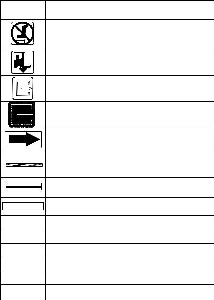
Definition of Symbols |
Symbol |
Definition |
123456789012345678901234567890121234567890123456789 |
|
|
Transfer of Heat, Hot Surface
Protective Earth (Ground)
Warning! Risk of Electrical Shock
Electrostatic Sensitive Device
Attention, Consult Manual for Further Instructions
Tip ‘N Tell Indicator
1-3
Listing of Warnings, Cautions and Symbols |
Uncrating/Installation Instructions |
P-122997-959 |
123456789012345678901234567890121234567890123456789 |
|
|
|
12345678901234567890123456789012123456789012345678 |
9 |
|
|
Definition of Symbols |
Symbol |
Definition |
|
12345678901234567890123456789012123456789012345678 |
9 |
|
|
|
|
|
Warning! Do Not Step Here. |
|
|
|
Fork Lift: Place Forks of the Fork Lift Here. |
|
|
|
Safety Exit: Push Here in Case of Emergency. |
|
|
|
Open this Side |
|
|
|
Rotation: Direction of the Rotating Device. |
|
|
|
Emergency Stop Guard Rails: Push to Stop Washer |
|
|
|
and De-energize Control. |
|
|
|
Load Delimitation: Do Not Place Load Over Marks. |
|
|
Preset at Factory |
Factory Adjustment: Do Not Adjust. |
|
|
A |
Amperage Rating of the Unit |
|
|
V |
Voltage Rating of the Unit |
|
|
~ |
Alternating Current |
|
|
kW |
Power Rating of the Unit |
|
|
Hz |
Frequency of the Unit |
fPhase of the Unit
1-4
P-122997-959 |
Uncrating/Installation Instructions |
Listing of Warnings, Cautions and Symbols |

SITE PREPARATION |
|
2 |
|
|
|
These specifications are intended to describe the technical infor-
Technical Specifications mation given on the nameplate of your washer and to state other relevant information. Check Equipment Drawing or Identification
nameplate, located on frame of mobile mechanical core, below main electrical box, for proper voltage and amperage.
This unit operates either on 208 V~, 3-phase, 60 Hz, 380/400/415 V~, 3-phase, 50 Hz or 480 V~, 3-phase, 60 Hz. Refer to Uncrating/Installation Manual (P-122997-959) for proper connection.
A protective ground conductor is required (Class 1 Equipment).
Installation Category II (Overvoltage Category).
If 130L equipped with Reliance® 130L Load/Unload Modules (Accessory): Refer to Uncrating/Installation Manual (P-920010- 101) for technical specifications and proper connection specific to Reliance 130L Load/Unload Modules.
AMPERAGE AND POWER CONSUMPTION
Maximum currents and power consumptions.
|
A |
kW |
208 V |
37.0 |
13.3 |
380/400/415 V |
13.0 |
9.3 |
480 V |
17.5 |
14.6 |
NOISE LEVEL
Equivalent Sound Pressure Level at work station (measured 1 meter away from equipment and at 1,6 meters from ground): 76.6 dB (A) for a freestanding unit with side panels and 72.6 dB (A) for an enclosed unit. (Results determined according to ISO-3746: 1979 Standard: Acoustics Determination of Sound Power Levels of Noise Sources Survey Method).
PERMISSIBLE ENVIRONMENTAL CONDITIONS
This washer is designed to give optimal results in an environment where maximum relative humidity is less than 85% and maximum operating temperature is 104°F (40°C).
2-1
Site Preparation |
Uncrating/Installation Instructions |
P-122997-959 |
Before Installing
Equipment
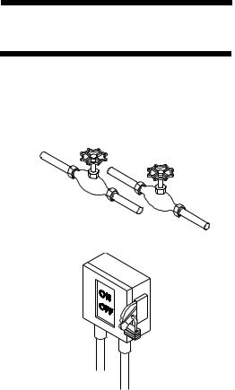
Figure 2-1. Utility Service Connections
1.Review permissible environmental conditions: this washer is designed to give optimal results in an environment where maximum relative humidity is less than 85% and maximum operating temperature is 104°F (40°C).
2.An optional seismic anchorage system is available for high risk seismic zones.
3.Review installation requirements:
a.Clearance - Clearance space shown on Equipment Drawing is necessary for ease of installation and proper operation and maintenance of washer (see Equipment Drawing 122-998-076 for 130 and 920-003-480 for 130L).
b.Barrier wall flange(s) installation - Refer to Equipment Drawing 122998-076 for 130 and 920-003-480 for 130L for installation.
c.Utility service lines:
•To allow service on unit without shutting off building supply lines, shutoff valves (not by STERIS) should be installed on steam, air and water lines to unit (see Figure 2-1). Shutoff valves must be capable of being locked in OFF position only.
•Disconnect switch (not by STERIS) must be installed on electric supply line (see Figure 2-1).
•Disconnect switches must be marked as the disconnecting device for the equipment and must be capable of being locked in OFF position only.
•If machine is installed next to other equipment, shutoff valves and disconnect switches should be located so that service can be shut off to one piece of equipment at a time.
•The disconnect device of the equipment must be within easy reach of the operator (preferably no more than 3 feet [1 m] away from equipment).
•Utility service requirements are shown on Equipment Drawing.
d.Electricity
•Unit requires either 208 V, 60 Hz, 3-phase, 3-wire; 380/400/ 415 V, 50 Hz, 3-phase, 3-wire; or 480 V, 60 Hz, 3-phase, 3-wire power.
For 208 V, 60 Hz, a 50 A disconnect switch and AWG #6 (16 mm) wire is recommended.
For 480 V, 60 Hz, a 30 A disconnect switch and AWG #10 (6 mm) wire is recommended.
For 380/400/415 V, 50 Hz, a 20 A disconnect switch and AWG #12 (4 mm2) wire is recommended.
2-2
P-122997-959 |
Uncrating/Installation Instructions |
Site Preparation |
If electrical supply is 380 V or 400 V, locate the 1000 VA transformer, inside the main electrical box, and connect red wire of primary side to 380 V (H2) tap connection.
•Check Equipment Drawing or Identification nameplate, located on frame of mobile mechanical core, below main electrical box (see Figure 3-3), for proper voltage and amperage.
•Installation category II (overvoltage category).
•This equipment is not intended to be connected close to the main supply of the building.
•This equipment needs to be installed according to local electrical codes.
4.This is a Class 1 equipment
A protective conductor connection is essential for the safe operation of the equipment. Check for presence of protective conductor at equipment terminal and verify if connection is well secured inside terminal with proper torque requirement.
•Torque requirement for supply conductor terminals: (L1-L2-L3): 0.89 -1.03 lb/ft (1,2 - 1,4 N•m)
•Protective conductor terminal: 16.96 - 29.50 lb/ft (23 - 40 N•m)
5.Make sure washer is placed, as shown on Equipment Drawing, in correct relation to building supply lines. If unit is not at installation site, refer to Section 3 for proper moving instructions.
6.If washer is pit-mounted:
•Pit must be clean.
•Pit drain piping should be level with pit floor to allow water to drain.
•Double check pit dimension for drain location.
2-3
Site Preparation |
Uncrating/Installation Instructions |
P-122997-959 |
This page intentionally left blank.
2-4
P-122997-959 |
Uncrating/Installation Instructions |
Site Preparation |

UNCRATING/INSTALLATION INSTRUCTIONS |
|
3 |
|
|
|
NOTE: Use a forklift to move crates.
Open Crates
>> Assembled Unit
NOTE: Uncrate on level floor as close to installation site as possible.
IMPORTANT: Bring in and uncrate only one crate at a time (see Figure 3-1).
A fully equipped, assembled unit should consist of 3 crates:
Model 130:
WARNING - PERSONAL INJURY AND/OR EQUIPMENT DAMAGE HAZARD: When moving the unit, use a forklift.
WARNING - LACERATION HAZARD: When removing bands, wear gloves and eye protection, and always use a tool specifically designed to cut the bands. The bands used to secure crates can cause personal injury when cut and tension is released.
•Crate A: Sump, floor, roof, non-service side panels, hardware box, control panel(s), doors.
Dimensions: W x L x H = 89” x 109” x 117” (226 x 277 x 297 cm). Weight: 4000 lb (1818 kg).
If option side panel add 200 lb (91 kg).
Model 130L:
•Crate A: Sump, floor, roof, non-service side panels, hardware box, control panel(s), doors.
Dimensions: W x L x H = 89” x 126” x 117” (226 x 320 x 297 cm). Weight: 4600 lb (2090 kg).
If option side panel add 200 lb (91 kg).
Both models:
• Crate C: Mechanical core.
Dimensions:W x L x H = 48” x 91” x 88” (226 x 320 x 297 cm) Weight: 2000 lb (909 kg).
• Crate D: Drying package.
Dimensions: W x L x H = 48” x 60” 44” (122 x 152 x 112 cm) Weight: 805 lb (365 kg).
And/or ramp (option)
Dimensions: W x L x H = 55” x 66” x 47” (140 x 168 x 119 cm) Weight: 550 lb (250 kg).
NOTE: There is no Crate B for assembled units.
1.Bring Crate A (washer) as close as possible to installation site (see Figure 3-2 for Center of Gravity).
2.Position unit to open wooden crate from top and side. Provide a clear work area on all sides.
3.Remove transparent plastic wrap from around crate.
4.Check tip indicator, located on upper left side of crates. Tip indicator contains a blue compound at the bottom of the indicator. If unit has been tipped, residue from the blue compound will be found higher up in the indicator. If unit has been tipped, contact your STERIS representative to determine if a service technician is required to inspect the equipment and determine if unit was damaged.
5.Remove wood panels from top and sides of washer.
3-1
Uncrating/Installation Instructions |
Uncrating/Installation Instructions |
P-122997-959 |

Mechanical Core
Amsco® Reliance® 130/130L
Cart and Utensil Washer/Disinfector
Drying System and other accessories
Tip N-Tell Indicators
Figure 3-1. Crates
3-2
P-122997-959 |
Uncrating/Installation Instructions |
Uncrating/Installation Instructions |
6.With skid under washer, using a fork lift, lift and bring washer close to installation site.
7.Using a fork lift, lift washer and remove skid from under washer.
8.Place washer into pit at final installation site. For proper installation, see Equipment Drawings (122-998-076 for 130 and 920-003-480 for 130L) and seismic anchorage report if option applies.
IMPORTANT: Be sure that suction piping is located on service side.
9.Floor mounted units:
•With a spirit level, level sump, end-to-end and side-to-side, adjusting four leveling legs (one at each corner of sump).
•Distance from door sill and floor can be adjusted between 5-1/4” to 7” (135 mm to 180 mm).
10.Pit-mounted units:
•For units requiring seismic anchorage, pit must be 78” [1980 mm].
•With a spirit level, level sump, end-to-end and side-to-side, adjusting four leveling legs (one at each corner of sump).
•To access leveling legs, external cabinet corners and front service panels may have to be removed, as follows:
a)Remove screws holding front service panel in place, and remove panel.
b)Remove screws holding non-control side external cabinet corner panel in place and remove panel.
NOTE: Leveling legs on control side panels can be reached from behind control side panel without having to remove panel.
•Make sure washer is flush with floor.
11.Inside wash chamber:
•Cut bands and remove control(s) from bottom of wash chamber.
>>Control Panel Installation NOTE: Before installing control, always verify with Customer if the
placement for main control with printer corresponds to configuration demanded.
NOTE: Control Configuration. If controls have been changed from one end to the other, align control with control door window, as follows:
1.Install controls on service side cabinet corner (5, 7) using hardware provided on controls (97, 98). Tighten all hardware (see Figure 3-6).
2.Close locks on control door.
3-3
Uncrating/Installation Instructions |
Uncrating/Installation Instructions |
P-122997-959 |
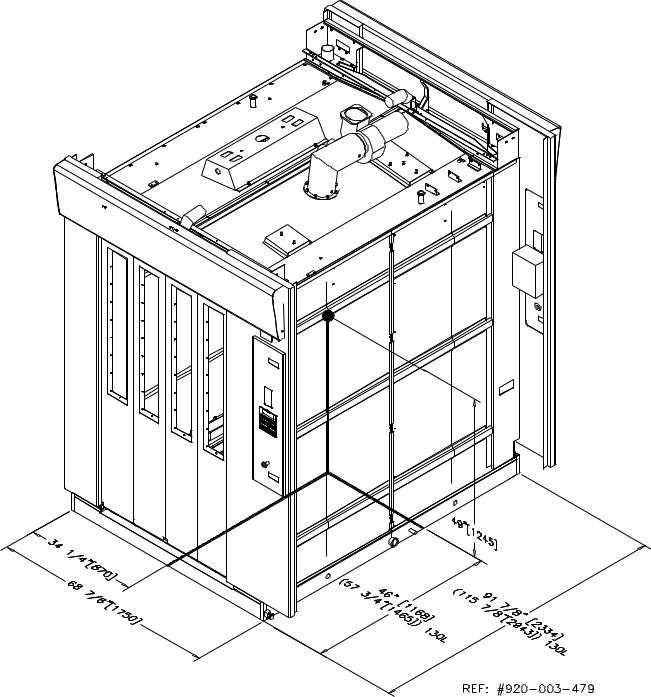
Figure 3-2. Amsco® Reliance® 130 /130L Cart and Utensil Washer/Disinfector
Center of Gravity
3-4
P-122997-959 |
Uncrating/Installation Instructions |
Uncrating/Installation Instructions |
3.Place control next to transparent membrane as if to operate control touch pad.
4.Align control with control door window.
5.Tighten nuts.
6.Use blank sticker to cover printer window on secondary control side (see Figure 3-13, Detail A).
•Remove bolts holding pieces of wood securing spray headers in place.
•Remove bolts and remove wooden floor frame inside wash chamber.
•Remove pieces of wood securing doors in place.
Once unit is in place, see page 3-45 (crate C) and page 3-51 (crate D) to complete washer installation.
3-5
Uncrating/Installation Instructions |
Uncrating/Installation Instructions |
P-122997-959 |
Non-Service Side
Right Side
Mechanical Core
Left Side |
|
Emergency Stop Pushbutton |
Tip N-Tell Indicators |
|
Service Side
Nameplate
Figure 3-3. Amsco® Reliance® 130/130L Cart and Utensil Washer/Disinfector, Reference View Point for all Installation Locations
3-6
P-122997-959 |
Uncrating/Installation Instructions |
Uncrating/Installation Instructions |

>> Disassembled Unit
WARNING - PERSONAL INJURY AND/OR EQUIPMENT DAMAGE HAZARD: When moving the unit, use a forklift.
WARNING - LACERATION/EYE INJURY HAZARD: When removing bands, wear gloves and eye protection, and always use a tool specifically designed to cut the bands. The bands used to secure crates can cause personal injury when cut and tension is released.
A fully equipped, disassembled unit should consist of 4 crates:
Model 130:
•Crate A: Sump, floor, roof, non-service side panels, hardware box.
Dimensions: W x L x H = 49” x 108” x 85” (125 x 274 x 216 cm) Weight: 2000 lb (909 kg).
Model 130L:
•Crate A: Sump, floor, roof, non-service side panels, hardware box.
Dimensions: W x L x H = 49” x 121” x 85” (125 x 307 x 216 cm) Weight: 2600 lb (1182 kg).
Both models:
•Crate B: End roof, piping, guards, doors, without side panel. Dimensions: W x L x H = 48” x 108” x 84” (122 x 274 x 213 cm) Weight: 2000 lb (909 kg).
If option side panel, add 200 lb (91 kg).
•Crate C: Mechanical core.
Dimensions: W x L x H = 48” x 91” x 88” (122 x 231 x 224 cm) Weight: 2000 lb (909 kg)
• Crate D: Drying package.
Dimensions: W x L x H = 48” x 60” x 44” (122 x 152 x 112 cm) Weight: 805 lb (365 kg)
And/or ramp (option)
Dimensions: W x L x H = 55” x 66” x 47” (140 x 168 x 119 cm) Weight: 550 lb (250 kg).
1.Remove transparent plastic wrap from around crate.
2.Check tip indicator, located on upper left side of crates. Tip indicator contains a blue compound at the bottom of the indicator. If unit has been tipped, residue from the blue compound will be found higher up in the indicator. If unit has been tipped, contact your STERIS representative to determine if a service technician is required to inspect the equipment and determine if unit was damaged.
3.Position unit to open wooden crate from top and side. Provide a clear work area on all sides.
4.Remove and discard side wooden panels.
IMPORTANT: Do not remove wooden top and side crate frames. All parts must be removed from crate ends. Do not remove parts from top of crates.
NOTE: Do not remove white protective adhesive paper from washer until after utilities are connected.
5.Mobile mechanical core:
•Check tip indicator, located on frame below main electrical box (see Figure 3-3). If unit has been tipped, contact your STERIS representative to determine if a service technician is required to inspect the equipment and determine if unit was damaged.
6.Repeat steps 1 through 3 for each crate.
IMPORTANT: Become familiar with components and installation instructions before installing washer (see Figure 3-3).
3-7
Uncrating/Installation Instructions |
Uncrating/Installation Instructions |
P-122997-959 |

Figure 3-4. Pit Mounted Unit
3-8
P-122997-959 |
Uncrating/Installation Instructions |
Uncrating/Installation Instructions |

Disassembled Unit
Assembly
>> Crate A
IMPORTANT: Uncrate and assemble only one crate at a time.
NOTE: Bolts, washers, nuts and other items needed for the assembly of the unit are in a box labeled “Hardware”, inside Crate A.
NOTE: Major components in crate are numbered to assist in inventory and assembly of unit. Review crate contents by matching numbers on components to numbers listed in parentheses and on Figures.
Contents:
•Sump, without floor and floor grating assembly (1).
•Cabinet corner panels, non-service side, left (2), right (4) and center panel (3 for 130L).
•Cabinet corner panels, service side, left (7), right (5) and center panel (6 for 130L).
•Roof mounting brackets (9).
•Non service side roof (10) and service side roof (11).
•Floor frame (31).
•Floor grating sections: 1 central section (32) 2 side sections (33).
•Main Control (97).
•Remote Control (98).
•Cabinet supports (99).
•Hardware Installation Kit: bolts, silicon, etc.
>> Sump Figure 3-4
WARNING - PERSONAL INJURY AND/OR EQUIPMENT DAMAGE HAZARD: When moving the unit, use a forklift.
WARNING - LACERATION HAZARD: When removing bolts, wear gloves to protect your hands.
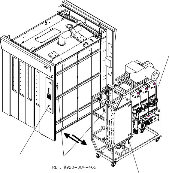
1.For complete installation details, see Equipment drawings (122998-076 for 130 and 920-003-480 for 130L) and Seismic Anchorage Report (920-004-485 for 130 and 920-004-484 for 130L) if option applies.
NOTE: For seismic installation, refer to Seismic Anchorage Instructions (included with Seismic Ancorage Kit).
2. Install sump on floor or in pit (if pit-mounted unit).
IMPORTANT: Be sure that suction piping is located on service side.
3.Floor mounted units:
•With a 24” spirit level, level sump, end-to-end and side-to-side, adjusting four leveling legs (one at each corner of sump).
•Distance from door sill and floor can be adjusted between 5-1/4” to 7” (135 mm to 180 mm).
3-9
Uncrating/Installation Instructions |
Uncrating/Installation Instructions |
P-122997-959 |

Detail D
Apply Silicone
Apply Silicone
Detail C
Sump Studs
Wall
Angle Bracket
Detail A
Detail B
Figure 3-5. Non-Service Side Walls
3-10
P-122997-959 |
Uncrating/Installation Instructions |
Uncrating/Installation Instructions |
4.Pit-mounted units:
•Make sure that no floor covering materials, such as tile or wood, will be installed after unit is into pit. If a floor covering is required, make sure unit is flush with floor covering.
•For units requiring seismic anchorage, pit must be 78” [1980 mm].
•With a 24” spirit level, level sump, end-to-end and side-to-side, adjusting four leveling legs (one at each corner of sump).
•Make sure washer is flush with floor.
5.Floor Gratings (Figure 3-12):
a)Install floor frame (31) inserting pins in holes (non-service side).
b)Install floor gratings [center (32), sides (33)] on floor frame.
>> Non-Service Side Walls Figure 3-5
IMPORTANT: At least two people are required to assemble side walls.
1.Spread a 3/8” (7 mm) bead of silicone on non-service side sump base (1).
2.Spread a 3/8” (7 mm) bead of silicone on side of left corner panel
(2) (and panel 2a for 130L).
NOTE: For washer installation with no clearance on non-service side of wash cabinet, bolt non-service side panels together (step 6), before bringing panels close to the washer.
3.Bring left corner panel (2) using installation cutout handles. Seat over sump, behind angle brackets (see Figure 3-5, Detail B).
NOTE: DO NOT use a pneumatic or impact tool to tighten nuts.
Finger-tighten the 1/4-20 bolts first to support the panel.
4.Finger-tighten hardware holding panel to sump, using 5/16” washers, 5/16” spring washers and nuts at bottom of sump (see Figure 3-5, Detail A). Use 1/4-20 x 3/4” bolts, 1/4” lockwashers and 1/4-20 nuts for angle brackets (see Figure 3-5, Detail B).
5.Repeat steps 2 to 4 to install center panel (3) (for 130L) and right non-service panel (4).
6.From outside, on non-service side, apply a bead of silicone and join non-service side panels together [2, 4 (3 for 130L)], using four 5/16-18 x 3/4” bolts, eight 5/16” washers and four 5/16” lockwashers provided.
7.Tighten wall to sump and secure wall to angle brackets (see Figure 3-5, Detail B).
3-11
Uncrating/Installation Instructions |
Uncrating/Installation Instructions |
P-122997-959 |

Detail A
Figure 3-6. Service Side Walls
3-12
P-122997-959 |
Uncrating/Installation Instructions |
Uncrating/Installation Instructions |
Loading...