


 Loading...
UNCRATING/INSTALLATION
INSTRUCTIONS
AMSCO® RELIANCE® 120/120L 220/220L
Cart and Utensil Washers
(09/22/00) |
P-122990-091 |
Rev. 2 |
|

LIMITATIONS OF LIABILITY AND INDEMNITY
IN NO CASE, WHETHER AS A RESULT OF A BREACH OF CONTRACT, BREACH OF WARRANTY OR TORT (INCLUDING STERIS'S OR CUSTOMER'S WILLFUL ACTS OR NEGLIGENCE OR STRICT LIABILITY) SHALL STERIS OR CUSTOMER BE LIABLE TO THE OTHER FOR ANY
CONSEQUENTIAL OR INCIDENTAL DAMAGES INCURRED BY THE OTHER, INCLUDING, BUT NOT LIMITED TO, LOSS OF REVENUE, PROFITS OR GOODWILL. HOWEVER, NOTHING
CONTAINED IN THIS AGREEMENT IS INTENDED TO RELIEVE EITHER STERIS OR CUS-
TOMER FROM CLAIMS, LIABILITY, DAMAGES OR EXPENSES RESULTING FROM BODILY INJURY, INCLUDING DEATH, OR FROM PROPERTY DAMAGE INCURRED DUE TO THE
WILLFUL ACTS, THE NEGLIGENCE OF OR THE STRICT LIABILITY OF THAT PARTY.
STERIS AGREES TO DEFEND, INDEMNIFY AND HOLD CUSTOMER HARMLESS FROM ANY AND ALL CLAIMS, LIABILITY, DAMAGES OR EXPENSES DUE TO PERSONAL INJURIES,
INCLUDING DEATH, TO EMPLOYEES OF STERIS AND CUSTOMER AND TO THIRD PARTIES
AND FOR PROPERTY DAMAGE TO THE EXTENT OF THE WILLFUL ACTS OF THE NEGLI-
GENCE OF STERIS OR THE STRICT LIABILITY OF STERIS CAUSED BY THE ACTS OR OMISSIONS OF STERIS. CUSTOMER AGREES TO DEFEND, INDEMNIFY AND HOLD STERIS
HARMLESS FROM ANY AND ALL CLAIMS, LIABILITY, DAMAGES OR EXPENSES DUE TO
PERSONAL INJURIES, INCLUDING DEATH, TO EMPLOYEES OF CUSTOMER AND STERIS AND TO THIRD PARTIES AND FROM PROPERTY DAMAGE TO THE EXTENT OF THE WILLFUL
ACTS OR THE NEGLIGENCE OF CUSTOMER OR THE STRICT LIABILITY OF CUSTOMER
CAUSED BY THE ACTS OR OMISSIONS OF CUSTOMER.
WARNING - COPYING PROHIBITED
This manual is protected by Federal Copyright Law, which provides for damages of up to $20,000, as well as criminal fines and imprisonment, for unauthorized copying.

A WORD FROM STERIS CORPORATION
Follow each step of the Uncrating/Installation instructions in the order presented. Open the crate(s) carefully to avoid damage to the equipment inside. If you find any indication of damage to the equipment (no matter how slight), show it to your supervisor.
To properly install this unit, you will need the Equipment Drawings (previously furnished), showing all utility service and space requirements. If drawings cannot be located, replacement copies may be obtained by writing, faxing or telephoning STERIS giving the serial and model numbers of your equipment.
Once installed, equipment operation should be tested by a qualified service technician prior to your usage of the equipment.
If STERIS supervision is desired for installing and starting up this equipment, contact your local STERIS representative.
A thorough preventive maintenance program is essential to safe Service Information and proper equipment operation. You are encouraged to contact your STERIS representative concerning extended service maintenance agreements to give your washer planned maintenance, assuring equipment performance according to factory specifications. A global network of skilled service specialists can provide periodic inspections and adjustments to assure low-cost peak performance. STERIS representatives can provide information
regarding Annual Maintenance Agreements.
STERIS carries a complete line of accessories for use in this equipment. A STERIS representative will gladly review these with you.
Sales and Service Information: |
Technical Assistance: |
||
STERIS Corporation |
STERIS Engineering |
||
5960 Heisley Road |
Services |
||
Mentor, Ohio 44060 |
2424 West 23rd Street |
||
Tel.: |
440 354 2600 |
Erie, PA 16506 |
|
Fax : |
440 639 8199 |
Tel.: |
814 452 3100 |
|
|
Fax: |
814 870 8400 |
Manufacturing Plant: STERIS Canada Corporation 415, rue des Alleghanys Beauport (Quebec)
Canada G1C 4N4 Tel.: 418 664 1549 Fax: 418 664 0188
Web Site: www.steris.com
©2000 , STERIS All rights reserved. |
Printed in Canada. |
i
Table of Contents |
Uncrating/Installation Instructions |
122990-091 |

Indications for Use
Advisory
The Amsco® Reliance® 120/120L and 220/220L Cart and utensil Washers are high capacity mechanical washers intended for use in the efficient washing and drying of utensils, carts and other miscellaneus reusable items used in the care of patients.
These washers are specifically designed to only process goods as outlined in the Operator Manual, provided with unit. If there is any doubt about a specific material or product, contact the manufacturer of the product for the recommended washing technique.
A listing of the safety precautions to be observed when uncrating,
installing and testing this equipment can be found in Section 1 of these instructions. Do not begin uncrating/installing this equipment until you have become familiar with this information.
Any alteration of the washer not authorized or performed by STERIS Engineering Service which could affect its operation will void the warranty, could adversely affect washing efficacy, could violate national, state and local regulations, and could jeopardize your insurance coverage.
IMPORTANT: Be sure to check the Occupational Health and Safety Act, as well as local electric and plumbing codes, for any special requirements that may pertain to installation of this unit.
ii
122990-091 |
Uncrating/Installation Instructions |
Table of Contents |
TABLE OF CONTENTS
|
|
|
|
|
SECTION |
TITLE |
PAGE |
||
|
|
|
|
|
1 |
LISTING OF WARNINGS, CAUTIONS |
|
|
|
|
|
AND SYMBOLS ............................................... |
1-1 |
|
|
|
Definition of Symbols ...................................................... |
1-2 |
|
2 |
SITE PREPARATION ....................................... |
2-1 |
|
|
|
|
Before Instaling Equipment ............................................ |
2-1 |
|
3 |
UNCRATING/INSTALLATION |
|
|
|
|
|
INSTRUCTIONS .............................................. |
3-1 |
|
|
|
Open Crates ................................................................... |
3-1 |
|
|
|
Assembled Unit .............................................................. |
3-1 |
|
|
|
Disassembled Unit Assembly ......................................... |
3-5 |
|
|
|
Crate A ......................................................................... |
3-5 |
|
|
|
Crate B ......................................................................... |
3-7 |
|
|
|
Sump ...................................................................... |
3-7 |
|
|
|
Load Side and Service Side Panels ........................ |
3-9 |
|
|
|
Unload Side and Non-Service Side Panels ............. |
3-9 |
|
|
|
Roof ...................................................................... |
3-11 |
|
|
|
Crate C ...................................................................... |
3-11 |
|
|
|
Doors .................................................................... |
3-11 |
|
|
|
Control Panel Assembly ........................................ |
3-13 |
|
|
|
Guides and Traveling Spray Cart Assembly ......... |
3-13 |
|
|
|
"U" Bar Spray Nozzles .......................................... |
3-13 |
|
|
|
Guards ................................................................... |
3-15 |
|
|
|
Pulley Supports for Traveler System...................... |
3-15 |
|
|
|
Traveler Cable ...................................................... |
3-17 |
|
|
|
Crate D ...................................................................... |
3-21 |
|
|
|
Drying Option ....................................................... |
3-23 |
|
|
|
Options ................................................................. |
3-25 |
|
|
|
Final Assembly ..................................................... |
3-27 |
|
|
|
Accessories .................................................................. |
3-29 |
|
|
|
Crate E ....................................................................... |
3-29 |
|
|
|
Enclosure Walls ......................................................... |
3-29 |
|
|
|
Ramp ......................................................................... |
3-29 |
|
|
|
Manifold Cart ............................................................. |
3-29 |
|
|
|
Connect Utilities ............................................................ |
3-31 |
|
|
|
Cleanup ........................................................................ |
3-33 |
|
4 |
INSTALLATION CHECKLIST ........................... |
4-1 |
|
|
5 |
OPERATIONAL TEST ...................................... |
5-1 |
|
|
iii
Table of Contents |
Uncrating/Installation Instructions |
122990-091 |
TABLE OF ILLUSTRATIONS
|
|
|
|
|
|
FIGURE |
TITLE |
PAGE |
|
|
|
|
|
|
2-1 |
Utility Service Connections ........................................................... |
2-1 |
|
|
2-2 |
Identification Nameplate ............................................................... |
2-1 |
|
|
3-1 |
Remove Bands ............................................................................. |
3-2 |
|
|
3-2 |
Remove Packing Material ............................................................. |
3-2 |
|
|
3-3 |
Lift Washer Using Beams or eyebolts ........................................... |
3-2 |
|
|
3-4 |
Move Washer Using Rollers or Pipes ............................................ |
3-2 |
|
|
3-5 |
Crates ........................................................................................... |
3-4 |
|
|
3-6 |
Cabinet panel Assembly ............................................................... |
3-8 |
|
|
3-7 |
Install Door Hinges........................................................................ |
3-10 |
||
3-8 |
Guides, Traveler and "U" Bars Assembling .................................. |
3-12 |
||
3-9 |
Clutch Adjustment ........................................................................ |
3-16 |
||
3-10 |
Cable Adjustment ......................................................................... |
3-18 |
||
3-11 |
Options ......................................................................................... |
3-20 |
||
3-12 |
Options: Condenser ...................................................................... |
3-22 |
||
|
3-12A |
Options: Ventilation Duct and Automatic Vent Damper ................ |
3-24 |
|
3-13 |
Automatic Drying (Option) ............................................................ |
3-26 |
||
3-14 |
Drying Option ................................................................................ |
3-28 |
||
3-15 |
Enclosure Walls with Doors ........................................................... |
3-30 |
||
3-16 |
Accessories .................................................................................. |
3-32 |
||
5-1 |
Check Operation of Valves ........................................................... |
5-2 |
|
|
5-2 |
Check Transfer Valve on Water Temperature Booster Tank ......... |
5-2 |
|
|
5-3 |
Check Travelling Spray Manifold .................................................. |
5-2 |
|
|
5-4 |
Power ON/OFF Switch .................................................................. |
5-2 |
|
|
5-5 |
Clean Travelling Spray Manifold Hose Filter ................................. |
5-4 |
|
|
5-6 |
Clean Travelling Spray Manifold Nozzles ..................................... |
5-4 |
|
|
5-7 |
Install Pickup Tube into Detergent Container ............................... |
5-4 |
|
|
iv
122990-091 |
Uncrating/Installation Instructions |
Table of Contents |

LISTING OF WARNINGS, CAUTIONS AND |
1 |
SYMBOLS |
The following is a listing of the safety precautions which must be observed when uncrating, installing and operating this equipment. WARNINGS indicate the potential for danger to personnel, and CAUTIONS indicate the potential for damage to equipment. These precautions are repeated throughout the instructions.
WARNING - PERSONAL INJURY AND/OR EQUIPMENT DAMAGE HAZARD:
Use an overhead hoist to lift unit. Unit weighs in excess of 4000 lbs, with 60% of the weight on the service side of the unit.
DO NOT move crates once they have been opened.
WARNING - LACERATION/EYE INJURY HAZARD:
Wear eye protection and always use a tool specifically designed for cutting the bands. The bands used to secure this container can cause personal injury when cut and tension is released.
WARNING - ELECTRIC SHOCK AND/OR BURN HAZARD:
Make sure power is OFF when checking operation valves, and that machine is cool. Valves are energized when power is on and piping/valves are hot after machine has been run.
WARNING - BURN HAZARD:
Wear gloves and face protection and open door slowly if it is necessary to open door during a cycle. Hot water may be sprayed through door opening when checking automatic stop while washing is operating.
After pressing STOP, wait until water flow stops before opening door. Hot water/steam may be sprayed through door opening if door is opened too soon.
Make sure power switch is OFF and keep chamber door(s) open when entering chamber to check operation of safety cable. When power is ON and door is closed, a cycle can be started and hot water would be sprayed into chamber.
Allow piping to cool down before inspecting and/or cleaning supply-line strainers.
WARNING - FALL HAZARD:
To prevent falls, keep floors dry. Promptly clean up any spills or drippage.
CAUTION - POSSIBLE EQUIPMENT DAMAGE:
When removing adhesives from stainless steel, use a solvent specially formulated for that purpose. Rub in back-and-forth motion (in same direction as surface grain). Solvent rubbed in a circular motion or applied with a wire brush or steel wool on door and chamber assemblies can be harmful to stainless steel. Do not use solvents on painted surfaces.
Once three-phase power is connected, check pump for correct rotation. Incorrect pump rotation may result in pump damage and improper cleaning action.
When choosing a detergent, use one with a low chloride content. Detergents with a high chloride content can be harmful to stainless steel.
1-1
Listing of Warnings, Cautions and Symbols |
Uncrating/Installation Instructions |
122990-091 |

12345678901234567890123456789012123456
Symbols
2345678901234567890123456789012123456
1-2
Symbol |
Definition |
Tip'N Tell Indicator.
|
This Side Up. |
|
Maximum Relative Humidity. |
|
Keep Dry. |
|
Fragile. |
|
Do not Stack. |
|
Maximum Temperature. |
|
Open this Side. |
A |
Amperage Rating of the Unit. |
V |
Voltage Rating of the Unit. |
~Alternating Current
kW |
Power Rating of the Unit |
Hz |
Frequency of the Unit |
φPhase of the Unit
122990-091 |
Uncrating/Installation Instructions |
Listing of Warnings, Cautions and Symbols |
SITE PREPARATION |
2 |
Before Installing
Equipment
Lock
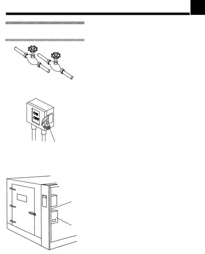
Figure 2-1. Utility Service
Connections
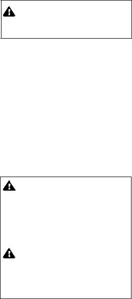
Identification Nameplate (on backside of front control panel)
Electrical Control
Box
Ref.: 920-008-394
Figure 2-2. Identification
Nameplate
IMPORTANT: Be sure to check the Occupational Health and Safety Act, as well as local electrical and plumbing codes, for any special requirements that may pertain to installation of this unit.
An optional seismic anchorage system is available for high risk seismic zones.
1.Review installation requirements.
a.Clearance − Clearance space shown on Equipment Drawing is necessary for easy installation and proper operation of unit.
b.Utility Service Lines:
•To allow service on unit without shutting off building supply lines, shutoff valves (not by STERIS) should be installed on steam and water lines to unit (see Figure 2-1). Shutoff valves must be capable of being locked in OFF position only.
•Disconnect switches (not by STERIS) should be installed in electric supply lines near washer (see Figure 2-1). Disconnect switches must be capable of being locked in the OFF position only.
•If this machine is installed next to other equipment, shutoff valves and disconnect switches should be located so that service can be shut off to one piece of equipment at a time.
•The disconnect device of the equipment must be within easy reach of the operator (preferably no more than 3 feet [1 m] away from equipment.
•Utility service requirements are shown on the Equipment Drawing.
c.Electricity:
•This machine requires either 208 V~, 60 Hz, 3-phase, 4- wire; 240 V~, 60 Hz, 3-phase, 3-wire; 480 V~, 60 Hz, 3- phase, 3-wire; or 600 V~, 60 Hz, 3-phase power.
•Check the Equipment Drawing or Identication Nameplate on backside of front control panel, next to the electrical control box, for proper voltage (see Figure 2-2).
NOTE: Washer is designed to be recessed through two walls. If unit is recessed through one wall or freestanding, service side must be enclosed.
2.Place washer in position as shown on Equipment Drawing, in correct relation to building supply lines. If unit is not at installation site, refer to Uncrating/Installations Instructions (Section 3) for proper moving instructions.
NOTE: Unit must be level. If necessary, use shims (not supplied with unit) to level machine. If the unit is not level, water level control and drain may not work properly.
2-1
Site Preparation |
Uncrating/Installation Instructions |
122990-091 |
3.Make sure washer is placed, as shown on Equipment Drawing, in correct relation to building supply lines.
4.If washer is pit mounted:
•Pit must be clean.
•Pit drain piping should be level with pit floor to allow water to drain.
2-2
122990-091 |
Uncrating/Installation Instructions |
Site preparation |
UNCRATING/INSTALLATION INSTRUCTIONS |
|
3 |
|
|
|
|
|
|
|
|
|
1234567890123456789012345678901212345 |
NOTE: This equipment weighs approximately: Model 120/120L |
||
Open Crates |
3500 lb (1590kg); Model 220/220L 4400 lb (2000 kg). Sixty per cent |
||
1234567890123456789012345678901212345 |
of its weight is concentrated on service side. Special handling |
||
equipment (i.e., an overhead hoist) is required to uncrate and handle it. Uncrate on a level floor as close to installation site as possible.
NOTE: If a drying package (vented or non-vented) has been ordered, it is packed in a separate crate: crate D. Uncrate this equipment after washer is installed.
NOTE: Uncrate on level floor as close to installation site as possible.
123456789012345678901234567890121234 5
Assembled Unit Assembly
1234567890123456789012345678901212345
WARNING - LACERATION/EYE INJURY HAZARD: Wear eye protection and always use a tool specifically designed for cutting the bands. The bands used to secure this container can cause personal injury when cut and tension is released.
PERSONAL INJURY AND/OR EQUIPMENT DAMAGE HAZARD: Use an overhead hoist to lift unit. Unit weighs in excess of 4000 lbs, with 60% of the weight on the service side of unit.
A fully equipped assembled unit should consist of one to three crates, depending upon options ordered:
• Crate A: Amsco® Reliance® 120/120L Cart and Utensil Washer 3500 lb (1590kg).
Crate A: Amsco® Reliance® 220/220L Cart and Utensil Washer 4400 lb (2000 kg).
• Crate D: Booster Fan Option and /or Optional Condenser or Drying Option (1225 lbs [556 kg]).
• Crate E (Optional): Exterior Panels 800 lb (360 kg).
NOTE: There are no crates B or C for assembled units.
1.Position crate so that there is a clear work area on all sides.
2.Carefully cut and remove bands from crate. Discard bands before continuing (Fig. 3-1).
3.Remove and discard polyethylene sheets (Fig. 3-2).
4.Remove and discard wooden panel from service side.
5.Remove and discard cardboard and service-side wooden frame.
6.Check tip indicator, located in service compartment, on backside of front control panel, below the controls. Tip indicator contains a blue compound at the bottom of the indicator. If unit has been tipped, residue from the blue compound will be found higher up in the indicator. If unit has been tipped, contact your STERIS representative to determine if a service technician is required to inspect the equipment and determine if unit was damaged (Fig. 3-2).
• Move the Washer:
1.Lift washer using beams or attaching eyebolts (not provided with washer) to the threaded inserts provided at each corner of washer (see Fig. 3-3).
NOTE: If attaching eyebolts, use four 3/4"-10 eyebolts.
2.Make sure that pit or floor are level before installing the unit. Use shims (not provided by STERIS) if necessary.
3.Refer to Equipment Drawing(s) and seismic anchorage report, if option applies, for clearance and proper installation.
4.Position rollers or pipes under washer as shown in Fig. 3-4.
5.Move washer to its permanent site.
3-1
Uncrating/installation Instructions |
Uncrating/Installation Instructions |
122990-091 |

Polyethylene Sheet
Polyethylene Sheet
Wood
Frame
Bands
|
Service Side |
Wood |
|
|
Wood Panel |
|
|
|
|
|
|||
Polyethylene Sheet |
Panel |
Cardboard |
Front Control Panel |
|
||
|
|
|||||
Ref.: 920008341 |
(tip indicator on |
Ref.: 920008342 |
||||
|
|
|||||
|
|
backside) |
|
|||
|
|
|
|
|
||
|
Figure 3-1. Remove Bands |
|
Figure 3-2. Remove Packing Material |
|||
or |
Beam |
|
|
|
|
|
|
or |
|
|
Roller |
|
Ref.: 920008332 |
Ref.: 920008333 |
|
|
|
Eyebolt |
|
|
Threaded Insert |
|
|
(each corner) |
|
|
Figure 3-3. Lift Washer Using |
Figure 3-4. Move Washer Using |
|
Beams or Eyebolts |
|
Rollers or Pipes |
3-2
122990-091 |
Uncrating/Installation Instructions |
Uncrating/Installation Instructions |
•Component box:
Interior light assembly (61); Sump filter (83); Stopper (88).
•Hardware kit (117-904-591 bolted): #16-14 receptacle connectors; white coupling connectors;
#12-10 ring terminals;
#1 connectors; #2 connectors; 14", 7-3/4" and 5" tie-wraps; 300ml clear silicone tube; silicone gun;
STERIS stainless steel cleaner; Thread Lock sealant; all-purpose wipers package; 1/4-20 x 1/2" bolts;
1/4-20 x 3/8" bolts; 1/4-20" nuts, 1/4" washers;
1/4" spring washers; 3/8-16 x1"bolts;
3/8" spring washers; 5/16-18 x 3/4" bolts; 5/16" spring washers;
8-32 x 1-1/2" truss head screws; 5/16" washers;
3/8-16 x 3/4" bolts.
•Hardware kit (117-910-020 weled): #16-14 reception connectors; white coupling connectors; #12-10 ring terminals;
#1 connectors; #2 connectors;
14", 7-3/4" and 5" tie-wraps; STERIS stainless cleaner; Thread lock sealant; all-purpose wipers package; 1/4-20 x 1/2" bolts;
1/4-20 x 3/8" bolts; 1/4-20" nuts,
1/4" washers;
1/4" spring washers; 3/8-16 x1"bolts;
3/8" spring washers; 5/16-18 x 3/4" bolts; 5/16" spring washers;
8-32 x 1-1/2" truss head screws; 5/16" washers; 3/8-16 x 3/4" bolts.
1.Prepare Washer for Installation (for proper installation, see Equipment Drawing):
a.Remove tape from control panel. Remove all tape from washer. Remove pin(s) securing chamber door(s).
b.Remove envelope containing Operator Manual and other printed material. Give to appropriate personnel.
Go to section: Crate D, E or Option, if any option applies.
3-3
Uncrating/installation Instructions |
Uncrating/Installation Instructions |
122990-091 |

Options
Amsco® Reliance® 120/120L
220/220L Cart and Utensil
Washer
Tip N'Tell Indicators
Figure 3-5. Crates
3-4
122990-091 |
Uncrating/Installation Instructions |
Uncrating/Installation Instructions |
2345678901234567890123456789012123456
Disassembled Unit
Assembly
1234567890123456789012345678901212345
WARNING - PERSONAL INJURY AND /OR EQUIPMENT DAMAGE HAZARD: DO NOT move crates once they have been opened.
A fully equipped, disassembled unit should consist of 4 or 5 crates, depending upon options ordered:
• Crate A: Model 120/120L: 2200 lbs (998 kg) Model 220/220L 2700 lbs (1225 kg)
• Crate B: Model 120/120L: 1800 lbs (816 kg) Model 220/220L 2200 lbs (998 kg)
• Crate C: Model 120/120L: 1100 lbs (500 kg) Model: 220/220L 1100 lbs (500 kg)
• Crate D: all models: 1225 lbs (556 kg). See Figures 3-12 and 3-12A.
• Crate E (Optional): Exterior Panels 800 lbs (360 kg)
Follow sequence as given in instructions. Each item to be assembled is tagged with a number and description. Items are bolted to crate to avoid damage. Provide a clear work area. Allow 3' (90 mm) from wall to crate on the rear and a space twice the large of crate in the front of it.
IMPORTANT: Bring in and uncrate crates A and B. Start opening crates by the ends, NOT by the sides.
NOTE: Use a forklift to move crates.
NOTE: Uncrate on level floor as close to installation site as possible.
» Crate A
WARNING - LACERATION/EYE INJURY HAZARD: Wear eye protection and always use a tool specifically designed for cutting the bands. The bands used to secure this container can cause personal injury when cut and tension is released.
PERSONAL INJURY AND/OR EQUIPMENT DAMAGE HAZARD: Use an overhead hoist to lift unit. Unit weighs in excess of 4000 lbs, with 60% of the weight on the service side of unit.
Contents (Reference figures 3-6 and 3-8):
•Unload side end (9A).
•Load side end (10A).
•Sump frame (23).
•Center non-service side (21) and center service side panels (22) (120L and 220L models only).
•Service side panels (24, 25).
•Non-service side panels (26, 27).
•Hardware kit #117-904-166: #16-14 receptacle connectors; white coupling connectors; #12-10 ring terminals;
#1 connectors; #2 connectors; 14",7-3/4" and 5" tie-wraps;
300 ml clear silicone tube; silicone gun; STERIS stainless steel cleaner;
Thread lock sealant; all-purpose wipers package; 1/4-20 x 1/2" bolts;
1/4-20 x 3/8" bolts; 1/4-20 x 3/4" bolts; 1/4-20 x 1" bolts; 5/16-18 x 3/4" bolts; 3/8-16 x 3/4" bolts; 338-16 x2" bolts;
6-32 x 3/8" truss head screws.
•Component box:
Unload side panel support (11b); Load side panel support (12B); Pulley for traveler (33A); Pulley support for traveler (40); Interior light assembly (61); Sump filter (83); Stopper (88); Hinge pins and washers; tri-clamp and gasket for water inlet; Operator Manual.
3-5
Uncrating/installation Instructions |
Uncrating/Installation Instructions |
122990-091 |
Loading...