


 Loading...
GAS DRYER OWNER'S MANUAL
GUIDE D’UTILISATION DE LA SÉCHEUSE AU GAZ
Table of Contents |
|
Dryer Safety ........................................................... |
2 |
Dryer Safety....................................................... |
2 |
Dryer Maintenance and Care .................................. |
5 |
Cleaning the Dryer Location ................................ |
5 |
Cleaning the Dryer Interior .................................. |
5 |
Removing Accumulated Lint................................ |
5 |
Cleaning the Lint Screen..................................... |
5 |
Changing the Drum Light (on some models)......... |
6 |
Check Your Vent System for Good Airflow ............ |
6 |
Maintain Good Airflow......................................... |
6 |
Nonuse, Storage, and Moving Care ..................... |
7 |
Special Instructions for Steam Models ................. |
7 |
Installation Instructions.......................................... |
7 |
Requirements......................................................... |
7 |
Tools and Parts .................................................. |
7 |
Location Requirements....................................... |
9 |
Gas Dryer Power Hookup – U.S.A. and |
|
Canada ........................................................... |
10 |
Gas Supply Requirements ................................ |
10 |
Installation ........................................................... |
11 |
Install Leveling Legs ......................................... |
11 |
Make Gas Connection – U.S.A. and |
|
Canada ........................................................... |
12 |
Venting Requirements ...................................... |
13 |
Plan Vent System............................................. |
13 |
Install Vent System........................................... |
15 |
Connect Inlet Hoses ......................................... |
15 |
Connect Vent ................................................... |
16 |
Level Dryer ...................................................... |
16 |
Complete Installation Checklist.......................... |
17 |
Table des matières |
|
Sécurité de la sécheuse ....................................... |
18 |
Sécurité de la sécheuse.................................... |
18 |
Entretien et réparation de la sécheuse ................. |
21 |
Nettoyage de l’emplacement de la |
|
sécheuse......................................................... |
21 |
Nettoyage de l’intérieur de la sécheuse.............. |
21 |
Retrait de la charpie accumulée ........................ |
21 |
Nettoyage du filtre à charpie.............................. |
21 |
Changement de l’ampoule d’éclairage du |
|
tambour (sur certains modèles) ......................... |
22 |
Vérification d’une circulation d’air adéquate |
|
pour le système d’évacuation ............................ |
22 |
Pour maintenir une bonne circulation d’air .......... |
22 |
Précautions à prendre avant des |
|
vacances, un entreposage ou un |
|
déménagement................................................ |
23 |
Instructions spécifiques pour les modèles |
|
vapeur............................................................. |
23 |
Instructions d’installation..................................... |
24 |
Spécifications ...................................................... |
24 |
Outils et pièces ................................................ |
24 |
Exigences d’emplacement ................................ |
25 |
Raccordement électrique de la sécheuse à |
|
gaz - états-unis et canada ................................. |
26 |
Spécifications de l’alimentation en gaz............... |
27 |
L’installation......................................................... |
28 |
Exigences d’emplacement ................................ |
28 |
Raccordement au gaz - états-unis et |
|
canada ............................................................ |
29 |
Exigences concernant l’évacuation.................... |
30 |
Planification des circuits de conduits.................. |
31 |
Installation du conduit d’évacuation ................... |
32 |
Raccordement des tuyaux d’alimentation ........... |
32 |
Raccordement du conduit d’évacuation.............. |
34 |
Réglage de l’aplomb de la sécheuse.................. |
34 |
Liste de vérification pour installation |
|
terminée .......................................................... |
35 |
W11361424A W11361425A-SP

DRYER SAFETY
Your safety and the safety of others are very important.
We have provided many important safety messages in this manual and on your appliance. Always read and obey all safety messages.
This is the safety alert symbol.
This symbol alerts you to potential hazards that can kill or hurt you and others.
All safety messages will follow the safety alert symbol and either the word “DANGER” or “WARNING.” These words mean:
 DANGER
 WARNING
You can be killed or seriously injured if you don't immediately follow instructions.
You can be killed or seriously injured if you don’t follow instructions.
All safety messages will tell you what the potential hazard is, tell you how to reduce the chance of injury, and tell you what can happen if the instructions are not followed.
IMPORTANT SAFETY INSTRUCTIONS
WARNING: To reduce the risk of fire, electric shock, or injury to persons when using your appliance, follow basic precautions, including the following:
Read all instructions before using the appliance.
Do not dry articles that have been previously cleaned in, washed in, soaked in, or spotted with gasoline, dry-cleaning solvents, or other flammable or explosive substances, as they give off vapors that could ignite or explode.
Do not allow children to play on or in the appliance. Close supervision of children is necessary when the appliance is used near children.
Before the appliance is removed from service or discarded, remove the door to the drying compartment.
Do not reach into the appliance if the drum is moving.
Do not install or store this appliance where it will be exposed to the weather.
Do not tamper with controls.
Do not repair or replace any part of the appliance or attempt any servicing unless specifically recommended in the usermaintenance instructions or in published user-repair instructions that you understand and have the skills to carry out.
Do not use fabric softeners or products to eliminate static unless recommended by the manufacturer of the fabric softener or product.
Do not use heat to dry articles containing foam rubber or similarly textured rubber-like materials.
Clean lint screen before or after each load.
Keep area around the exhaust opening and adjacent surrounding areas free from the accumulation of lint, dust, and dirt.
The interior of the appliance and exhaust duct should be cleaned periodically by qualified service personnel.
Do not place items exposed to cooking oils in your dryer. Items contaminated with cooking oils may contribute to a chemical reaction that could cause a load to catch fire. To reduce the risk of fire due to contaminated loads, the final part of a tumble dryer cycle occurs without heat (cool down period). Avoid stopping a tumble dryer before the end of the drying cycle unless all items are quickly removed and spread out so that the heat is dissipated.
Do not use replacement parts that have not been recommended by the manufacturer (e.g. parts made at home using a 3D printer).
See the Installation Instructions for grounding requirements and installation.
SAVE THESE INSTRUCTIONS
2

 WARNING — “Risk of Fire”
−Clothes dryer installation must be performed by a qualified installer.
−Install the clothes dryer according to the manufacturer's instructions and local codes.
−Do not install a clothes dryer with flexible plastic venting materials or flexible metal (foil type) duct. If flexible metal duct is installed, it must be of a specific type identified by the appliance manufacturer as suitable for use with clothes dryers. Flexible venting materials are known to collapse, be easily crushed, and trap lint. These conditions will obstruct clothes dryer airflow and increase the risk of fire.
−To reduce the risk of severe injury or death, follow all installation instructions.
−Save these instructions.
 WARNING
FIRE HAZARD
Failure to follow safety warnings exactly could result in serious injury, death, or property damage.
Do not install a booster fan in the exhaust duct.
Install all clothes dryers in accordance with the installation instructions of the manufacturer of the dryer.
 WARNING:
FIRE OR EXPLOSION HAZARD
Failure to follow safety warnings exactly could result in serious injury, death, or property damage.
−Do not store or use gasoline or other flammable vapors and liquids in the vicinity of this or any other appliance.
−WHAT TO DO IF YOU SMELL GAS:
•Do not try to light any appliance.
•Do not touch any electrical switch; do not use any phone in your building.
•Clear the room, building, or area of all occupants.
•Immediately call your gas supplier from a neighbor’s phone. Follow the gas supplier’s instructions.
•If you cannot reach your gas supplier, call the fire department.
−Installation and service must be performed by a qualified installer, service agency, or the gas supplier.
3
WARNING: Gas leaks cannot always be detected by smell.
Gas suppliers recommend that you use a gas detector approved by UL or CSA.
For more information, contact your gas supplier.
If a gas leak is detected, follow the “What to do if you smell gas” instructions.
IMPORTANT: The gas installation must conform with local codes, or in the absence of local codes, with the National Fuel Gas Code, ANSI Z223.1/NFPA 54, or the National Gas and Propane Installation Code, CSA B149.1.
The dryer must be electrically grounded in accordance with local codes, or in the absence of local codes, with the National Electrical Code, ANSI/NFPA 70, or the Canadian Electrical Code, Part 1, CSA C22.1.
In the State of Massachusetts, the following installation instructions apply:
Installation and repairs must be performed by a qualified or licensed contractor, plumber, or gas fitter qualified or licensed by the State of Massachusetts.
Acceptable Shut-off Devices: Gas Cocks and Ball Valves installed for use shall be listed.
A flexible gas connector, when used, must not exceed 4 feet (121.9 cm).
IMPORTANT SAFETY INSTRUCTIONS
WHEN DISCARDING OR STORING YOUR OLD CLOTHES DRYER, REMOVE THE DOOR.
SAVE THESE INSTRUCTIONS
4

DRYER MAINTENANCE AND CARE
Cleaning the Dryer Location
To clean:
1.Remove the lint screen. If necessary, press the tab to release and open the lint screen. Roll lint off the screen with your fingers. Do not rinse or wash screen to remove lint. Wet lint is hard to remove.
 WARNING
Explosion Hazard
Keep flammable materials and vapors, such as gasoline, away from dryer.
Do not dry anything that has ever had anything flammable on it (even after washing).
Place dryer at least 18 inches (460 mm) above the floor for a garage installation.
Failure to do so can result in death, explosion, or fire.
Keep dryer area clear and free from items that would block the airflow for proper dryer operation. This includes clearing piles of laundry in front of the dryer.
Cleaning the Dryer Interior
To clean dryer drum:
1.Use a mild hand dish detergent mixed at a low concentration with nonflammable cleaner or very warm water, and rub with a soft cloth.
Rinse well with a wet sponge or towel.
Tumble a load of clean clothes or towels to dry drum.
2.Use a microfiber cloth and hot water in a spray bottle to clean the drum and a second microfiber towel to dry.
NOTE: Garments that contain unstable dyes, such as denim blue jeans or brightly colored cotton items, may discolor the rear of the dryer interior. These stains are not harmful to your dryer and will not stain future loads of clothes. Dry unstable dye items inside out to avoid transfer of dye.
Removing Accumulated Lint
From inside the dryer cabinet:
Lint should be removed every 2 years, or more often, depending on dryer usage. Cleaning should be done by a qualified appliance service or ventilation system cleaner.
From the exhaust vent:
Lint should be removed every 2 years, or more often, depending on dryer usage.
Cleaning the Lint Screen
Every load cleaning:
The lint screen may be located either in the door opening or the top of the dryer depending on model. A screen blocked by lint can increase drying time.
2. Push the lint screen firmly back into place.
IMPORTANT:
Do not run the dryer with the lint screen loose, damaged, blocked, or missing. Doing so can cause overheating and damage to both the dryer and fabrics.
If lint falls off the screen into the dryer during removal, check the exhaust hood and remove the lint. See “Venting Requirements” in the Installation Instructions.
Clean space where lint screen is located, as needed. Using a vacuum, gently remove any lint that has accumulated outside of the lint screen.
As-needed cleaning:
Laundry detergent and fabric softener residue can build up on the lint screen. This buildup can cause longer drying times for your clothes, or cause the dryer to stop before your load is completely dry. The screen is probably clogged if lint falls off while the screen is in the dryer. Clean the lint screen with a nylon brush every 6 months, or more frequently, if it becomes clogged due to a residue buildup.
To wash:
1.Roll lint off the screen with your fingers.
2.Wet both sides of lint screen with hot water.
5

3.Wet a nylon brush with hot water and liquid detergent. Scrub lint screen with the brush to remove residue buildup.
4.Rinse screen with hot water.
5.Thoroughly dry lint screen with a clean towel. Reinstall screen in dryer.
Changing the Drum Light (on some models)
1.Unplug dryer or disconnect power.
2.Open the dryer door. Locate the light bulb cover on the back wall of the dryer. Using a Phillips-head screwdriver or 1/4" (6.35 mm) nut driver or socket wrench, remove the screw located in the lower right-hand corner of the cover. Remove the cover.
3.Turn bulb counterclockwise. Replace the bulb with a 10 W appliance bulb only. Replace the cover and secure with the screw.
4.Plug in dryer or reconnect power.
Accessories and replacement parts are available for your model. For ordering and contact information, please reference your Quick Start Guide.
Check Your Vent System for Good Airflow
 WARNING
Fire Hazard
Use a heavy metal vent.
Do not use a plastic vent.
Do not use a metal foil vent.
Failure to follow these instructions can result in death or fire.
Good Airflow
Along with heat, dryers require good airflow to efficiently dry laundry. Proper venting will reduce your drying times and improve your energy savings. See Installation Instructions.
The venting system attached to the dryer plays a big role in good airflow. Blocked or crushed vents as well as improper venting installation will reduce air flow and dryer performance.
Service calls caused by improper venting are not covered by the warranty and will be paid by the customer, regardless of who installed the dryer. To clean or repair venting, contact a venting specialist.
Maintain Good Airflow
Cleaning your lint screen before each load.
Replace plastic or foil vent material with 4" (102 mm) diameter heavy, rigid vent material.
Use the shortest length of vent possible.
Use no more than four 90° elbows in a vent system; each bend and curve reduces airflow.
Remove lint and debris from the exhaust hood.
Remove lint from the entire length of the vent system at least every 2 years. When cleaning is complete, be sure to follow the Installation Instructions for final product check.
Clear away items from the front of the dryer.
6

Nonuse, Storage, and Moving Care
Install and store your dryer where it will not freeze. Because some water may stay in the hose, freezing can damage your dryer. If storing or moving your dryer during freezing weather, winterize it.
Nonuse or Storage Care
If you will be on vacation or not using your dryer for an extended period of time, you should:
1.Unplug dryer or disconnect power.
2.Clean lint screen. See “Cleaning the Lint Screen.”
3.Close shutoff valve in gas supply line.
4.Turn off the water supply to the dryer. This helps to avoid unintended flooding (due to a water pressure surge) while you are away.
Moving Care
1.Unplug the power supply cord.
2.Gas models only: Close shutoff valve in gas supply line.
3.Gas models only: Disconnect gas supply line pipe and remove fittings attached to dryer pipe.
4.Gas models only: Cap the open gas supply line.
5.Steam models only: Shut off water faucet. Disconnect the water inlet hose from faucet; then drain the hose. Transport hose separately.
6.Make sure leveling legs are secure in dryer base.
7.Use tape to secure dryer door.
8.On models with base trim, remove base trim before moving dryer. See “Install and remove base trim (on some models)” for details.
Special Instructions for Steam Models
Water Inlet Hose
Replace inlet hose and hose screen after 5 years of use to reduce the risk of hose failure. Periodically inspect and replace inlet hose if bulges, kinks, cuts, wear, or leaks are found.
When replacing your inlet hose, record the date of replacement.
To winterize the dryer:
1.Unplug dryer or disconnect power.
2.Shut off water faucet.
3.Disconnect water inlet hose from faucet and drain.
To use the dryer again:
 WARNING
Electrical Shock Hazard
Plug into a grounded 3 prong outlet.
Do not remove ground prong.
Do not use an adapter.
Do not use an extension cord.
Failure to follow these instructions can result in death, fire, or electrical shock.
1.Flush water pipes. Reconnect water inlet hose to faucet. Turn on water faucet.
2.Plug in dryer or reconnect power as described in the Installation Instructions.
Reinstalling the Dryer
Follow the Installation Instructions to locate, level, and connect the dryer.
INSTALLATION INSTRUCTIONS
REQUIREMENTS
Tools and Parts
NOTE: Install the clothes dryer according to the manufacturer’s instructions and local codes.
Gather required tools and parts before starting installation. Read and follow the instructions provided with any tools listed here.
Tools Needed for All Installations:
Flat-blade screwdriver |
#2 Phillips screwdriver |
1/4" and 5 /16" nut driver
Level
7

Pliers or slip-joint pliers
Tape measure
Utility knife
Tin snips (new vent installations)
Parts Supplied (all models):
Leveling legs (4) (Length and appearance of legs may vary according to model)
Parts package is located in dryer drum. Check that all parts are included.
NOTE: Do not use leveling legs supplied with dryer if installing with a pedestal or a stack kit.
Parts Needed (steam models):
Caulking gun and compound (new vent installations)
Vent clamps
8" (203 mm) or 10" (254 mm) pipe wrench
Pipe-joint compound resistant to propane gas
Adjustable wrench that opens to 1" (25 mm) or hex-head socket wrench
Putty knife
Wire stripper (direct-wire installations)
“Y” connector |
2' (0.6 m) inlet hose |
5' (1.52 m) inlet hose
Rubber washer
Parts Needed (not supplied with dryer):
Additional parts may be required, depending on your installation. Check local codes. Check existing electrical supply and venting. See “Electrical Requirements” and “Venting Requirements” before purchasing parts.
Mobile home installations require metal exhaust system hardware available for purchase from the dealer from whom you purchased your dryer. For further information, please refer to the Quick Start Guide for service contact information.
Available Accessories:
Refer to your Quick Start Guide for contact and ordering information.
8
Location Requirements
 WARNING
Explosion Hazard
Keep flammable materials and vapors, such as gasoline, away from dryer.
Do not dry anything that has ever had anything flammable on it (even after washing).
Place dryer at least 18 inches (460 mm) above the floor for a garage installation.
Failure to do so can result in death, explosion, or fire.
Check code requirements. Some codes limit, or do not permit, installation of the dryer in garages, closets, mobile homes, or sleeping quarters. Contact your local building inspector.
You will need:
A location allowing for proper exhaust installation. See “Venting Requirements.”
A separate 15 A or 20 A circuit for gas dryers.
A grounded electrical outlet located within 2 ft. (610 mm) of either side of the dryer. See “Electrical Requirements” in the “Gas Dryer Power Hookup” section.
A sturdy floor to support dryer and a total weight (dryer and load) of 200 lbs. (90.7 kg). The combined weight of a companion appliance should also be considered.
Level floor with maximum slope of 1" (25 mm) under entire dryer. If slope is greater than 1" (25 mm), install Extended Dryer Feet Kit. If not level, clothes may not tumble properly and automatic sensor cycles may not operate correctly. Installing on carpet is not recommended.
For garage installation, place dryer at least 18" (460 mm) above floor. If using a pedestal, you will need 18" (460 mm) to bottom of dryer.
Steam models only: Cold water faucets located within 4 ft. (1.2 m) of the water fill valves, and water pressure of 20–100 psi (137.9–689.6 kPa). You may use your washer’s water supply by utilizing the necessary parts noted in “Parts needed.”
The dryer must not be installed or stored in an area where it will be exposed to water and/or weather.
IMPORTANT: Do not operate your dryer at temperatures below 45°F (7°C). Lower temperatures may cause dryer not to shut off at end of automatic sensor cycles, resulting in longer drying times.
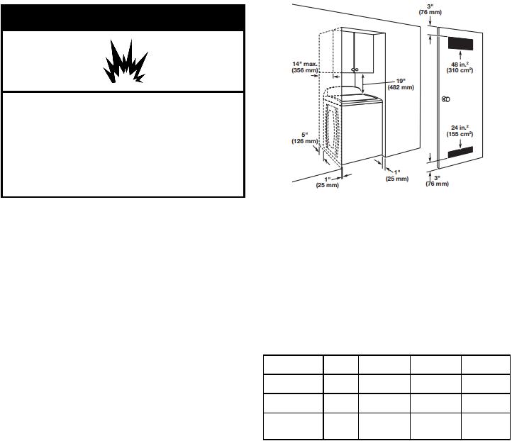
Installation clearances:
For each arrangement, consider allowing more space for ease of installation and servicing, spacing for companion appliances, and clearances for walls, doors, and floor moldings. Space must be large enough to allow the door to fully open. Add spacing on all sides of dryer to reduce noise transfer. If a closet door or louvered door is installed, top and bottom air openings in door are required.
Spacing for recessed area or closet
NOTE: No other fuel-burning appliance can be installed in the same closet as a dryer.
The dimensions shown are for the minimum spacing allowed.
Additional spacing should be considered for ease of installation and servicing.
Additional clearances might be required for wall, door, and floor moldings.
Additional spacing of 1" (25 mm) on all sides of the dryer is recommended to reduce noise transfer.
For closet installation with a door, minimum ventilation openings in the top and bottom of the door are required. Louvered doors with equivalent ventilation openings are acceptable.
Companion appliance spacing should also be considered.
Minimum installation clearances (dryer only):
|
Front |
Sides |
Rear |
Top |
Recessed |
NA |
0" (0 mm) |
0" (0 mm) |
0" (0 mm) |
Closet |
NA |
0" (0 mm) |
0" (0 mm) |
0" (0 mm) |
Under |
NA |
1" (25 mm) |
0" (0 mm) |
0" (0 mm) |
Counter |
|
|
|
|
0" (0 mm) rear spacing is allowed for straight-back venting only. For steam models only, inlet hose must not be kinked.
Mobile Home – Additional installation requirements
This dryer is suitable for mobile home installations. The installation must conform to the Manufactured Home Construction and Safety Standard, Title 24 CFR, Part 3280 (formerly the Federal Standard for Mobile Home Construction and Safety, Title 24, HUD Part 280) or the Standard for Mobile Homes, CAN/CSAZ240 MH.
Mobile home installations require:
Metal exhaust system hardware, which is available for purchase from your dealer.
Mobile Home Installation Hold-Down Kit. See your Quick Start Guide for more information.
Special provisions must be made in mobile homes to introduce outside air into the dryer. The opening (such as a nearby window) should be at least twice as large as the dryer exhaust opening.
9

Gas Dryer Power Hookup – U.S.A. |
Gas Supply Requirements |
and Canada |
WARNING |
Electrical Requirements |
|
WARNING |
|
Electrical Shock Hazard
Plug into a grounded 3 prong outlet.
Do not remove ground prong.
Do not use an adapter.
Do not use an extension cord.
Failure to follow these instructions can result in death, fire, or electrical shock.
120 V, 60 Hz, AC-only, 15 A or 20 A fused electrical supply is required. A time-delay fuse or circuit breaker is recommended. It is also recommended that a separate circuit serving only this dryer be provided. Do not use an extension cord.
GROUNDING INSTRUCTIONS
For a grounded, cord-connected appliance:
This appliance must be grounded. In the event of a malfunction or breakdown, grounding will reduce the risk of electric shock by providing a path of least resistance for electric current. This appliance is equipped with a cord having an equipment-grounding conductor and a grounding plug. The plug must be plugged into an appropriate outlet that is properly installed and grounded in accordance with all local codes and ordinances.
WARNING: Improper connection of the equipmentgrounding conductor can result in a risk of electric shock. Check with a qualified electrician or serviceman if you are in doubt as to whether the appliance is properly grounded. Do not modify the plug provided with the appliance: if it will not fit the outlet, have a proper outlet installed by a qualified electrician.
SAVE THESE INSTRUCTIONS
Explosion Hazard
Use a new CSA International approved gas supply line.
Install a shut-off valve.
Securely tighten all gas connections.
If connected to propane, have a qualified person make sure gas pressure does not exceed 13 (33 cm) water ʺ column.
Examples of a qualified person include: licensed heating personnel, authorized gas company personnel, and authorized service personnel.
Failure to do so can result in death, explosion, or fire.
Gas Type
Natural Gas:
This dryer is equipped for use with natural gas. It is certified by UL for use with propane gas with appropriate conversion.
Your dryer must have the correct burner for the type of gas in your home. Burner information is located on the rating plate in the door well of your dryer. If this information does not agree with the type of gas available, contact your dealer or reference the contact information listed on your Quick Start Guide.
Propane Gas Conversion:
IMPORTANT: Conversion must be made by a qualified technician.
No attempt shall be made to convert the appliance from the gas specified on the model/serial rating plate for use with a different gas without consulting your gas company.
Gas Supply Line
Option 1 (Recommended Method)
Flexible stainless steel gas connector:
If local codes permit, use a new flexible stainless steel gas connector (Design-Certified by the American Gas Association or CSA International) to connect your dryer to the rigid gas supply line. Use an elbow and a 3/8" flare x 3/8" NPT adapter fitting between the stainless steel gas connector and the dryer gas pipe, as needed, to prevent kinking.
Option 2 (Alternate Method)
Approved aluminum or copper tubing:
Must include 1/8" NPT minimum plugged tapping accessible for test gauge connection, immediately upstream of the gas connection to the dryer.
1/2" IPS pipe is recommended.
3/8" approved aluminum or copper tubing is acceptable for lengths under 20 ft. (6.1 m) if local codes and gas supplier permit.
If you are using natural gas, do not use copper tubing.
Lengths over 20 ft. (6.1 m) should use larger tubing and a different size adapter fitting.
10
If your dryer has been converted to use propane gas, 3/8" propane-compatible copper tubing can be used. If the total length of the supply line is more than 20 ft. (6.1 m), use larger pipe.
NOTE: Pipe-joint compounds that resist the action of propane gas must be used. Do not use PTFE plumber’s tape.
Must include shutoff valve.
In the U.S.A.:
An individual manual shutoff valve must be installed within six
(6) ft. (1.8 m) of the dryer in accordance with the National Fuel Gas Code, ANSI Z223.1. The location should be easy to reach for opening and closing.
In Canada:
An individual manual shutoff valve must be installed in accordance with the B149.1, Natural Gas and Propane Installation Code. It is recommended that an individual manual shutoff valve be installed within six (6) ft. (1.8 m) of the dryer. The location should be easy to reach for opening and closing.
A.3/8" flexible gas connector
B.3/8" pipe-to-flare adapter fitting
C.1/8" NPT minimum plugged tapping
D.1/2" NPT gas supply line
E.Gas shutoff valve
Gas Supply Connection Requirements
Use an elbow and a 3/8" flare x 3/8" NPT adapter fitting between the flexible gas connector and the dryer gas pipe, as needed to avoid kinking.
Use only pipe-joint compound. Do not use PTFE plumber’s tape.
This dryer must be connected to the gas supply line with a listed flexible gas connector that complies with the standard for connectors for gas appliances, ANSI Z21.24 or CSA 6.10.
Burner Input Requirements
Elevations above 2,000 ft. (610 m)
When installed above 2,000 ft. (610 m), a 4% reduction of the burner Btu rating shown on the model/serial number plate is required for each 1,000 ft. (305 m) increase in elevation.
Gas supply pressure testing
The dryer must be disconnected from the gas supply piping system during pressure testing at pressures greater than 1/2 psi (3.45 kPa).
Dryer gas pipe
The gas pipe that comes out through the rear of your dryer has a 3/8" male pipe thread.
INSTALLATION
Install Leveling Legs
 WARNING
Excessive Weight Hazard
Use two or more people to move and install or uninstall appliance.
Failure to do so can result in back or other injury.
1. Prepare dryer for leveling legs
To avoid damaging floor, use a large flat piece of cardboard from dryer carton; place under entire back edge of dryer. Firmly grasp dryer body (not console panel) and gently lay dryer down on cardboard.
2. Screw in leveling legs
Leveling leg with diamond marking
Leveling leg without diamond marking
Using a wrench and tape measure, screw leveling leg into leg holes until bottom of foot is approximately 1/2" (13 mm) to
1 1/2" (38 mm) from bottom of the dryer.
For leveling legs with the diamond marking:
Screw legs into leg holes by hand. Use a wrench to finish turning legs until diamond marking is no longer visible.
Place a carton corner post from dryer packaging under each of the two dryer back corners. Stand the dryer up. Slide the dryer on the corner posts until it is close to its final location. Leave enough room to connect the exhaust vent.
11
Loading...